2009 NISSAN TIIDA e control
[x] Cancel search: e controlPage 973 of 4331

CVT
N
O P
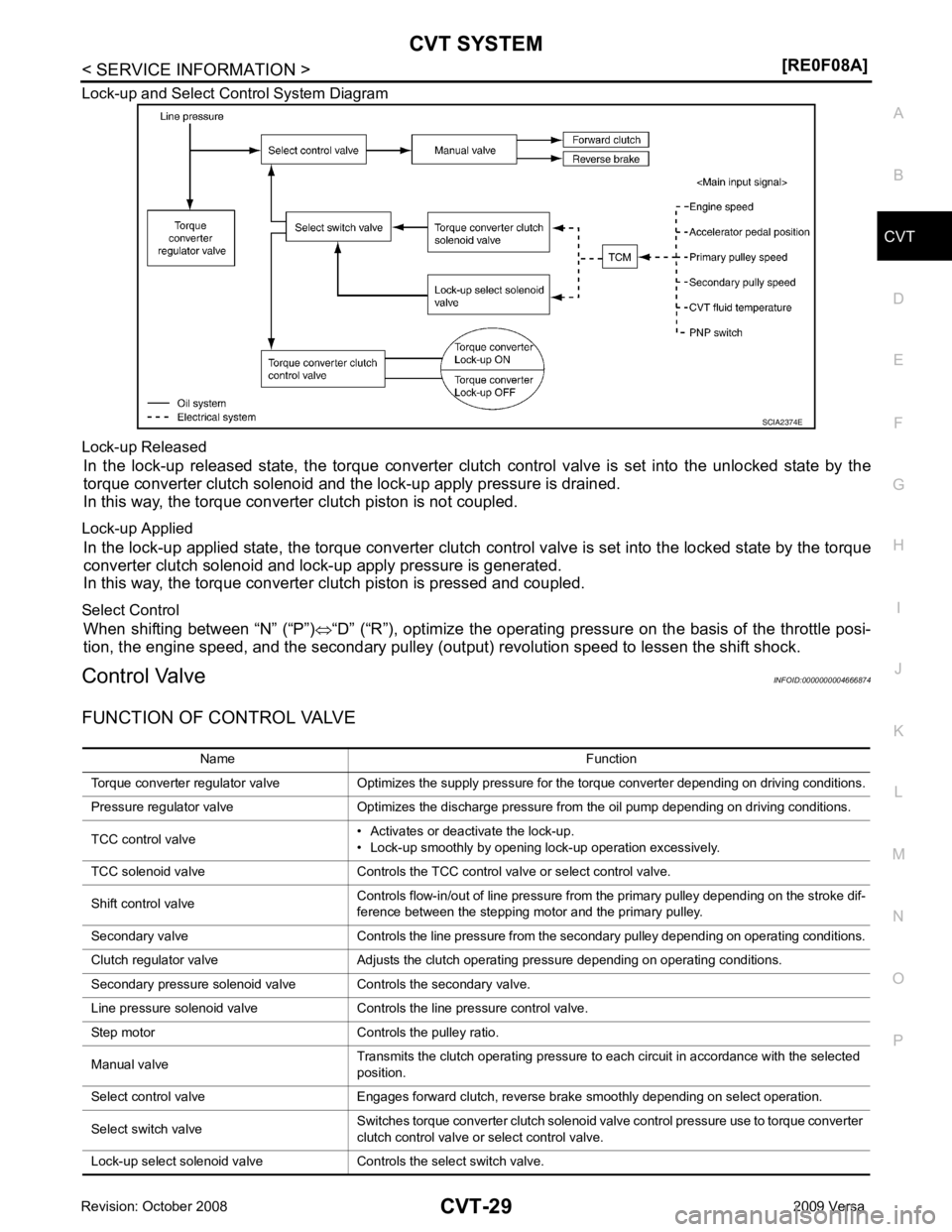
Lock-up and Select Control System Diagram
Lock-up Released In the lock-up released state, the torque converter clutch control valve is set into the unlocked state by the
torque converter clutch solenoid and the lock-up apply pressure is drained.
In this way, the torque converter clutch piston is not coupled.
Lock-up Applied In the lock-up applied state, the torque converter clutch control valve is set into the locked state by the torque
converter clutch solenoid and lock-up apply pressure is generated.
In this way, the torque converter clutch piston is pressed and coupled.
Select Control When shifting between “N” (“P”) ⇔“D” (“R”), optimize the operating pressure on the basis of the throttle posi-
tion, the engine speed, and the secondary pulley (out put) revolution speed to lessen the shift shock.
Control Valve INFOID:0000000004666874
FUNCTION OF CONTROL VALVE
Page 977 of 4331

CVT
N
O P
TROUBLE DIAGNOSIS
DTC Inspection Priority Chart INFOID:0000000004666880
If some DTCs are displayed at the same time, perform inspections one by one based on the following priority
chart.
NOTE:
If DTC “U1000 CAN COMM CIRCUIT” is displayed with other DTCs, first perform the trouble diagnosis
for “DTC U1000 CAN COMMUNICATION LINE”. Refer to CVT-60 .
Fail-Safe INFOID:0000000004666881
The TCM has an electrical fail-safe mode. This mode make s it possible to operate even if there is an error in a
main electronic control input/output signal circuit.
FAIL-SAFE FUNCTION If any malfunction occurs in a sensor or solenoid, th is function controls the CVT to make driving possible.
Output Speed Sensor (Secondary Speed Sensor) The shift pattern is changed in accordance with throttle position when an unexpected signal is sent from the
output speed sensor (secondary speed sensor) to the TCM. The overdrive-off mode is inhibited, and the tran-
saxle is put in “D”.
Input Speed Sensor (Primary Speed Sensor) The shift pattern is changed in accordance with throttle position and secondary speed (vehicle speed) when
an unexpected signal is sent from the input speed sensor (primary speed sensor) to the TCM. The sport mode
is inhibited, and the transaxle is put in “D”.
PNP Switch If an unexpected signal is sent from the PNP switch to the TCM, the transaxle is put in “D”.
CVT Fluid Temperature Sensor If an unexpected signal is sent from the CVT fluid temper ature sensor to the TCM, the gear ratio in use before
receiving the unexpected signal is maintained or the gear ratio is controlled to keep engine speed under 3500
rpm.
Transmission Fluid Pressure Sens or A (Secondary Pressure Sensor)
• If an unexpected signal is sent from the transmission fl uid pressure sensor A (secondary pressure sensor) to
the TCM, the secondary pressure feedback control is stopped and the offset value obtained before the non-
standard condition occurs is used to control line pressure.
• If transmission fluid pressure sensor A (secondary pre ssure sensor) error signal is input to TCM, secondary
pressure feedback control stops, but line pressure is controlled normally.
Pressure Control Solenoid A (Line Pressure Solenoid) If an unexpected signal is sent from the solenoid to t he TCM, the pressure control solenoid A (line pressure
solenoid) is turned OFF to achieve the maximum fluid pressure.
Pressure Control Solenoid B (Secondary Pressure Solenoid) If an unexpected signal is sent from the solenoid to t he TCM, the pressure control solenoid B (secondary pres-
sure solenoid) is turned OFF to achieve the maximum fluid pressure.
Torque Converter Clutch Solenoid If an unexpected signal is sent from the solenoid to t he TCM, the torque converter clutch solenoid is turned
OFF to cancel the lock-up.
Step Motor If an unexpected signal is sent from the step motor to the TCM, the step motor coil phases “A” through “D” are
all turned OFF to hold the gear ratio used right before the non-standard condition occurred.
CVT Lock-up Select Solenoid Priority Detected items (DTC)
1 U1000 CAN communication line
2 Except above
Page 978 of 4331
![NISSAN TIIDA 2009 Service Repair Manual CVT-34< SERVICE INFORMATION >
[RE0F08A]
TROUBLE DIAGNOSIS
If an unexpected signal is sent from the solenoid to t he TCM, the CVT lock-up select solenoid is turned OFF to
cancel the lock-up.
TCM Power NISSAN TIIDA 2009 Service Repair Manual CVT-34< SERVICE INFORMATION >
[RE0F08A]
TROUBLE DIAGNOSIS
If an unexpected signal is sent from the solenoid to t he TCM, the CVT lock-up select solenoid is turned OFF to
cancel the lock-up.
TCM Power](/manual-img/5/57398/w960_57398-977.png)
CVT-34< SERVICE INFORMATION >
[RE0F08A]
TROUBLE DIAGNOSIS
If an unexpected signal is sent from the solenoid to t he TCM, the CVT lock-up select solenoid is turned OFF to
cancel the lock-up.
TCM Power Supply (Memory Back-up)
Transaxle assembly is protected by limiting the engine torque when the memory back-up power supply (for
controlling) from the battery is not supplied to TCM. Normal statues is restored when turning the ignition switch
OFF to ON after the normal power supply.
How to Perform Trouble Diagnosis for Quick and Accurate Repair INFOID:0000000004666882
INTRODUCTION
The TCM receives a signal from the vehicle speed sensor, PNP switch and provides shift control or lock-up
control via CVT solenoid valves.
The TCM also communicates with the ECM by means of a signal
sent from sensing elements used wit h the OBD-related parts of the
CVT system for malfunction-diagnostic purposes. The TCM is capa-
ble of diagnosing malfunctioning parts while the ECM can store mal-
functions in its memory.
Input and output signals must always be correct and stable in the
operation of the CVT system. The CVT system must be in good
operating condition and be free of valve seizure, solenoid valve mal-
function, etc.
It is much more difficult to diagnose an error that occurs intermit-
tently rather than continuously. Mo st intermittent errors are caused
by poor electric connections or improper wiring. In this case, careful
checking of suspected circuits ma y help prevent the replacement of
good parts.
A visual check only may not find the cause of the errors. A road test
with CONSULT-III (or GST) or a circuit tester connected should be
performed. Follow the "WORK FLOW" .
Before undertaking actual checks, take a few minutes to talk with a
customer who approaches with a driveability complaint. The cus-
tomer can supply good information about such errors, especially
intermittent ones. Find out what symptoms are present and under
what conditions they occur. A “DIAGNOSTIC WORKSHEET” as
shown on the example (Refer to "Diagnostic Worksheet Chart" )
should be used.
Start your diagnosis by looking for “conventional” errors first. This will
help troubleshoot driveability errors on an electronically controlled
engine vehicle.
Also check related Service bulletins.
WORK FLOW
A good understanding of the malfunction conditions can make troubleshooting faster and more accurate.
In general, each customer feels differently about a malf unction. It is important to fully understand the symp-
toms or conditions for a customer complaint.
Make good use of the two sheets provided, "Informati on From Customer" and "Diagnostic Worksheet Chart" ,
to perform the best troubleshooting possible.
Work Flow Chart SAT631IB
SAT632I
SEF234G
Page 983 of 4331

CVT
N
O P
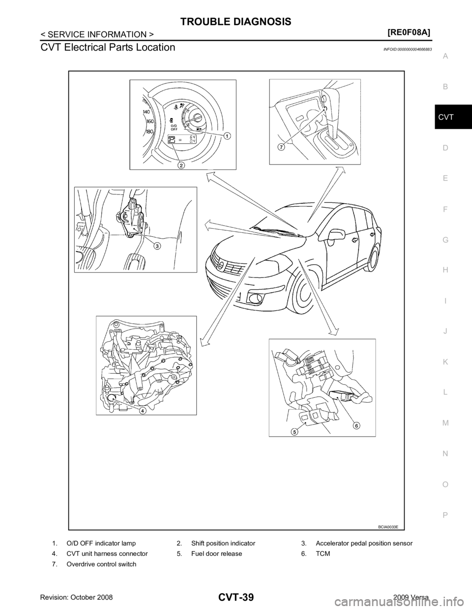
CVT Electrical Parts Location
INFOID:0000000004666883
1. O/D OFF indicator lamp 2. Shift position indicator 3. Accelerator pedal position sensor
4. CVT unit harness connector 5. Fuel door release 6. TCM
7. Overdrive control switch
Page 988 of 4331
![NISSAN TIIDA 2009 Service Repair Manual CVT-44< SERVICE INFORMATION >
[RE0F08A]
TROUBLE DIAGNOSIS
Road Test INFOID:0000000004666886
DESCRIPTION
• The purpose of the test is to determine overall performance of CVT and analyze causes of pro NISSAN TIIDA 2009 Service Repair Manual CVT-44< SERVICE INFORMATION >
[RE0F08A]
TROUBLE DIAGNOSIS
Road Test INFOID:0000000004666886
DESCRIPTION
• The purpose of the test is to determine overall performance of CVT and analyze causes of pro](/manual-img/5/57398/w960_57398-987.png)
CVT-44< SERVICE INFORMATION >
[RE0F08A]
TROUBLE DIAGNOSIS
Road Test INFOID:0000000004666886
DESCRIPTION
• The purpose of the test is to determine overall performance of CVT and analyze causes of problems.
• The road test consists of the following three parts:
1. “Check Before Engine Is Started” CVT-45 .
2. “Check at Idle” CVT-45 .
3. “Cruise Test” CVT-47 .
Judgement Possible cause
Idle speed Low for all positions
(“P”, “R”, “N”, “D”, “L”) Possible causes include malfunctions in the pressure supply system and low oil pump output.
For example
• Oil pump wear
• Pressure regulator valve or plug sticking or spring fatigue
• Oil strainer ⇒ oil pump ⇒ pressure regulator valve passage oil leak
• Engine idle speed too low
Only low for a specific
position Possible causes include an oil pressure leak in a passage or device related to the position after
the pressure is distributed by the manual valve.
High Possible causes include a sensor malfunction or malfunction in the line pressure adjustment
function.
For example
• Accelerator pedal position signal malfunction
• CVT fluid temperature sensor malfunction
• Pressure control solenoid A (line pressure solenoid) malfunction (sticking in OFF state, filter
clog, cut line)
• Pressure regulator valve or plug sticking
Stall speed Line pressure does
not rise higher than
the line pressure for
idle. Possible causes include a sensor malfunction or malfunction in the pressure adjustment func-
tion.
For example
• Accelerator pedal position signal malfunction
• TCM malfunction
• Pressure control solenoid A (line pressure solenoid) malfunction (shorting, sticking in ON state)
• Pressure regulator valve or plug sticking
The pressure rises,
but does not enter the
standard position. Possible causes include malfunctions in the pressure supply system and malfunction in the pres-
sure adjustment function.
For example
• Accelerator pedal position signal malfunction
• Pressure control solenoid A (line pressure solenoid) malfunction (sticking, filter clog)
• Pressure regulator valve or plug sticking
Only low for a specific
position Possible causes include an oil pressure leak in a passage or device related to the position after
the pressure is distributed by the manual valve. SAT786A
Page 993 of 4331
![NISSAN TIIDA 2009 Service Repair Manual TROUBLE DIAGNOSIS
CVT-49
< SERVICE INFORMATION >
[RE0F08A] D
E
F
G H
I
J
K L
M A
B CVT
N
O P 9.
CHECK ENGINE BRAKE FUNCTION — PART 3
1. Move selector lever to “L” position.
2. Check engine brake NISSAN TIIDA 2009 Service Repair Manual TROUBLE DIAGNOSIS
CVT-49
< SERVICE INFORMATION >
[RE0F08A] D
E
F
G H
I
J
K L
M A
B CVT
N
O P 9.
CHECK ENGINE BRAKE FUNCTION — PART 3
1. Move selector lever to “L” position.
2. Check engine brake](/manual-img/5/57398/w960_57398-992.png)
TROUBLE DIAGNOSIS
CVT-49
< SERVICE INFORMATION >
[RE0F08A] D
E
F
G H
I
J
K L
M A
B CVT
N
O P 9.
CHECK ENGINE BRAKE FUNCTION — PART 3
1. Move selector lever to “L” position.
2. Check engine brake.
Does engine braking effectively reduce speed in “ L ” position?
YES >> 1. Stop the vehicle.
2. Perform self-diagnosis. Refer to CVT-51, " CONSULT-III Function (TRANSMISSION) " .
NO >> Mark the box of CVT-163, " Vehicle Does Not Decelerate by Engine Brake " on the
CVT-34, " How
to Perform Trouble Diagnosis for Quick and Accurate Repair " . Then continue trouble diagnosis.
Vehicle Speed When Shifting Gears INFOID:0000000004666890
Numerical value data are reference values.
CAUTION:
Lock-up clutch is engaged when vehi cle speed is approximately 18 km/h (11 MPH) to 90 km/h (56 MPH).
TCM Terminal and Reference Value INFOID:0000000004666891
TCM HARNESS CONNECTOR TERMINAL LAYOUT
TERMINALS AND REFERENCE VALUES FOR TCM Data are reference values and are measured between each terminal and ground.
Engine type Throttle position Shift pattern
Engine speed (rpm)
At 40 km/h (25 MPH) At 60 km/h (37 MPH)
MR18DE 8/8
“D” position
Overdrive-off mode “L” position 3,600 - 4,500 4,400 - 5,300
2/8 “D” position 1,300 - 3,100 1,400 - 3,500
Overdrive-off mode 2,200 - 3,000 2,800 - 3,600 “L” position 3,200 - 4,100 3,900 - 4,800 WCIA0717E
Terminal
Wire
color Item Condition Data (Approx.)
1 GR Pressure control
solenoid valve A
(Line pressure
solenoid valve)
and Release your foot from the accelerator pedal. 5.0 - 7.0 V
Press the accelerator pedal all the way down. 1.0 - 3.0 V
2 LG Pressure control
solenoid valve B
(Secondary
pressure sole-
noid valve) Release your foot from the accelerator pedal. 5.0 - 7.0 V
Press the accelerator pedal all the way down. 3.0 - 4.0 V
3 SB Torque converter
clutch solenoid
valve When vehi-
cle cruises in
“D” position. When CVT performs lock-up. 6.0 V
When CVT does not perform lock-up. 1.0 V
Page 998 of 4331

How to Perform Trouble Diag-
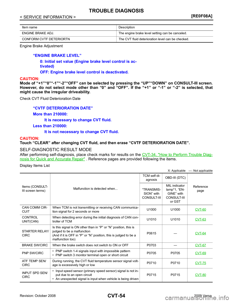
nosis for Quick and Accurate Repair " . Reference pages are provided following the items.
Display Items List X: Applicable —: Not applicable
Item name Description
ENGINE BRAKE ADJ. The engine brake level setting can be canceled.
CONFORM CVTF DETERIORTN The CVT fluid deterioration level can be checked. CONTROL
UNIT(CAN) When detecting error during the initial diagnosis of CAN con-
troller of TCM U1010 U1010
CVT-63STARTER RELAY/
CIRC Is this signal is ON other than in “P” or “N” position, this is
judged to be a malfunction
(And if it is OFF in “P” or “N” position, this is judged to be a
malfunction too) P0615 —
CVT-64BRAKE SW/CIRC When the brake switch does
not switch to ON or OFF P0703 — CVT-67PNP SW/CIRC
• PNP switch 1-4 signals input with impossible pattern
• PNP switch 3 monitor terminal open or short circuit P0705 P0705
CVT-69ATF TEMP SEN/
CIRC During running, the CVT fluid temperature sensor signal volt-
age is excessively high or low P0710 P0710
CVT-75INPUT SPD SEN/
CIRC • Input speed sensor (primary speed sensor) signal is not in-
put due to an open circuit
• An unexpected signal is input when vehicle is being driven P0715 P0715
CVT-80
Page 999 of 4331
![NISSAN TIIDA 2009 Service Repair Manual CVT
N
O P
VEH SPD SEN/
CIR AT • Signal from vehicle speed sensor CVT [Output speed sen-
sor (Secondary speed sensor)] not input due to open or
short circuit
• Unexpected signal input during runni NISSAN TIIDA 2009 Service Repair Manual CVT
N
O P
VEH SPD SEN/
CIR AT • Signal from vehicle speed sensor CVT [Output speed sen-
sor (Secondary speed sensor)] not input due to open or
short circuit
• Unexpected signal input during runni](/manual-img/5/57398/w960_57398-998.png)
CVT
N
O P
VEH SPD SEN/
CIR AT • Signal from vehicle speed sensor CVT [Output speed sen-
sor (Secondary speed sensor)] not input due to open or
short circuit
• Unexpected signal input during running P0720 P0720
CVT-84ENGINE SPEED
SIG • TCM does not receive the CAN communication signal from
the ECM
• Engine speed is too low while driving P0725 —
CVT-89BELT DAMG Unexpected gear ratio detected P0730 —
CVT-91TCC SOLENOID/
CIRC Normal voltage not applied to solenoid due to open or short
circuit P0740 P0740
CVT-92A/T TCC S/V
FNCTN • CVT cannot perform lock-up even if electrical circuit is good
• TCM detects as irregular by comparing difference value with slip rotation
• There is big difference engine speed and primary speed when TCM lock-up signal is on P0744 P0744
CVT-97L/PRESS SOL/
CIRC • Normal voltage not applied to solenoid due to open or short
circuit
• TCM detects as irregular by comparing target value with monitor value P0745 P0745
CVT-99PRS CNT SOL/A
FCTN Unexpected gear ratio was detected in the LOW side due to
excessively low line pressure P0746 P0746
CVT-104PRS CNT SOL/B
FCTN Secondary pressure is too high or too low compared with the
commanded value while driving P0776 P0776
CVT-106PRS CNT SOL/B
CIRC • Normal voltage not applied to solenoid due to cut line,
short, or the like
• TCM detects as irregular by comparing target value with
monitor value P0778 P0778
CVT-108TR PRS SENS/A
CIRC Signal voltage of the transmission fluid pressure sensor A
(secondary pressure sensor) is too high or too low while driv-
ing P0840 P0840
CVT-113PRESS SEN/
FNCTN Correlation between the values of the transmission fluid pres-
sure sensor A (secondary pressure sensor) and the tranmis-
sion fluid pressure sensor B (primary pressure sensor) is out
of specification P0841 —
CVT-117TR PRS SENS/B
CIRC Signal voltage of the transmission fluid pressure sensor B
(primary pressure sensor) is too high or too low while driving P0845 P0845
CVT-119SEC/PRESS
DOWN Secondary fluid pressure is too low compared with the com-
manded value while driving P0868 —
CVT-123TCM-POWER
SUPPLY • When the power supply to the TCM is cut OFF, for example
because the battery is removed, and the self-diagnosis
memory function stops
• This is not a malfunction message (Whenever shutting OFF a power supply to the TCM, this message appears on
the screen) P1701 —
CVT-125TP SEN/CIRC A/T
TCM does not receive the proper accelerator pedal position
signals (input by CAN communication) from ECM P1705 —
CVT-129ESTM VEH SPD
SIG*2 • CAN communication with the ABS actuator and the electric
unit (control unit) is malfunctioning
• There is a great difference between the vehicle speed sig-
nal from the ABS actuator and the electric unit (control
unit), and the vehicle speed sensor signal P1722 —
CVT-131Items (CONSULT-
III screen terms) Malfunction is detected when... TCM self-di-
agnosis OBD-III (DTC)
Reference page
“TRANSMIS-
SION” with
CONSULT-III MIL indicator
lamp*1, “EN- GINE” with
CONSULT-III
or GST