Page 1694 of 1903
Downloaded from www.Manualslib.com manuals search engine IMMOBILIZER CONTROL MODULE
Description
The vehicle security system uses an Immobilizer control module as an anti-theft device that prevents the engine from
starting if an incorrect key is inserted into the ignition switch.
Operation
When an incorrect key is inserted into the ignition switch, the vehicle security system senses the incorrect key and
sends a signal to the Immobilizer control module. The Engine Control Module (ECM) receives the signal from Immo-
bilizer control module via the R-Line. The ECM then disables the engine from starting.
15–11 0Chery Automobile Co., Ltd.
Page 1696 of 1903
Downloaded from www.Manualslib.com manuals search engine Immobilizer Control Module Connector Pin-Out Table
PINCIRCUIT IDENTIFICATION PINCIRCUIT IDENTIFICATION
1 Continuous Supply Voltage 7Diagnostic Link K
2 GND 8W-Line
3 -9Coil (GND)
4 Ignition Switch 10Coil (ANT B)
5 R-Line 11Coil (ANT A)
6-—-
IMMOBILIZER CONTROL MODULE
15–11 2Chery Automobile Co., Ltd.
Page 1699 of 1903

Downloaded from www.Manualslib.com manuals search engine Remote Keyless Entry (RKE) Inoperative
No Response From Remote Keyless Entry (RKE) Transmitter
1.CHECK BATTERY
• Check battery of the RKE transmitter.
Is the battery voltage of the RKE transmitter normal?
Ye s>>Go to the next step.
No
>>This concern has been caused by the transmitter battery.
Go to step 4.
2.CHECK THE IGNITION LOCK CYLINDER CONDITION
• Check the ignition lock cylinder for proper operation.
Is the check result normal?
Ye s>>Go to the next step.
No
>>Repair or replace the ignition lock cylinder key switch.
3.PERFORM THE RKE TRANSMITTER MATCH PROCEDURE
• Close all the doors.
• Insert the ignition key into the ignition switch which has lost synchronization in LOCK position.
• Press any button on the RKE transmitter within 5 seconds.
• Pull the ignition key out of the ignition switch.
• Try to operate the RKE transmitter.
Does the RKE transmitter operate properly?
Ye s>>Erase all codes before returning the vehicle to the customer.
No
>>Go to the next step.
DIAGNOSIS & TESTING
15
15–11 5Chery Automobile Co., Ltd.
Page 1700 of 1903

Downloaded from www.Manualslib.com manuals search engine 4.PERFORM THE RKE TRANSMITTER MATCH WITH THE X-431
• Replace the RKE transmitter.
• Connect the X-431 scan tool to the Data Link Connector (DLC), press the POWER key to start the X-431 (use
the most current software available).
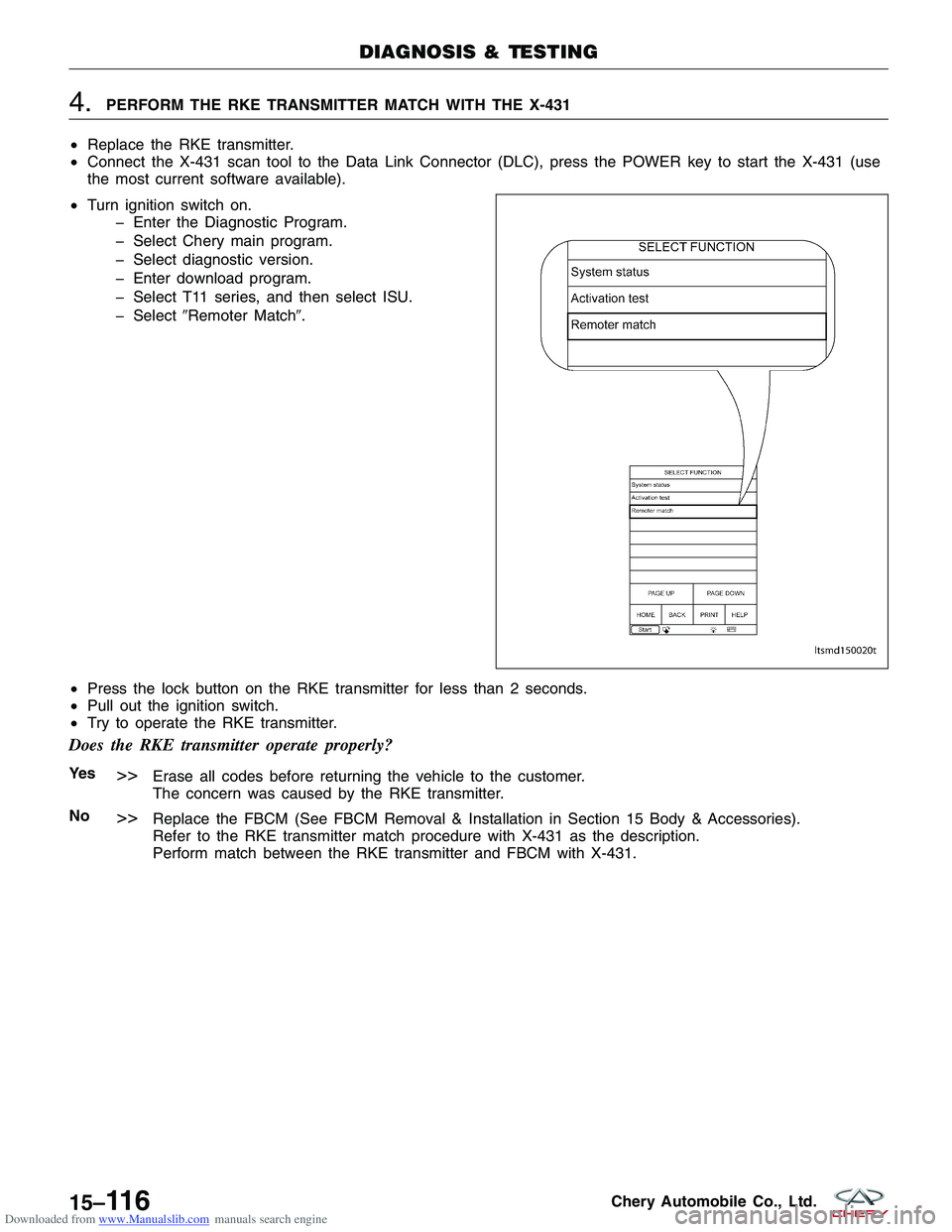
• Turn ignition switch on.
� Enter the Diagnostic Program.
� Select Chery main program.
� Select diagnostic version.
� Enter download program.
� Select T11 series, and then select ISU.
� Select �Remoter Match�.
• Press the lock button on the RKE transmitter for less than 2 seconds.
• Pull out the ignition switch.
• Try to operate the RKE transmitter.
Does the RKE transmitter operate properly?
Ye s>>Erase all codes before returning the vehicle to the customer.
The concern was caused by the RKE transmitter.
No
>>Replace the FBCM (See FBCM Removal & Installation in Section 15 Body & Accessories).
Refer to the RKE transmitter match procedure with X-431 as the description.
Perform match between the RKE transmitter and FBCM with X-431.
DIAGNOSIS & TESTING
LTSMD150020T
15–11 6Chery Automobile Co., Ltd.
Page 1702 of 1903

Downloaded from www.Manualslib.com manuals search engine On Board Diagnostic Logic
•Self-diagnosis detection logic.
DTC NO. DTC DEFINITION DTC DETECTION
CONDITION POSSIBLE CAUSE
B1000 ECU Defect, Internal
Errors Immobilizer control
module detects an internal failure. •
Immobilizer control
module
DTC Confirmation Procedure:
Before performing the following procedure, confirm that battery voltage is more than 12 V.
•Turn ignition switch off.
• Connect the X-431 scan tool to the Data Link Connector (DLC) - use the most current software available.
• Turn ignition switch on, with the scan tool, view and erase stored DTCs in the Immobilizer control module.
• Try to start the engine.
• Turn ignition switch off, and wait a few seconds, then turn ignition switch on.
• With the scan tool, view DTCs in the Immobilizer control module.
• If the DTC is detected, the condition is current. Go to Diagnostic Procedure - Step 1.
• If the DTC is not detected, the DTC condition is intermittent (See Diagnostic Help and Intermittent DTC Trou-
bleshooting in Section 15 Body & Accessories for more information).
NOTE :
While performing electrical diagnosis & testing, always refer to the electrical schematics for specific circuit
and component information.
Diagnostic Procedure
1.CHECK DTC
• Perform DTC confirmation procedure.
Is DTC B1000 present?
Ye s>>Go to the next step.
No
>>The condition that caused the DTC to set is currently not present (See Diagnosis & Testing Diagnostic
Help in Section 15 Body & Accessories).
2.CHECK IMMOBILIZER CONTROL MODULE ELECTRICAL CONNECTOR
• Turn ignition switch off.
• Disconnect the Immobilizer control module electrical
connector C-025 (1).
• Inspect the electrical connector for damage.
Is the electrical connector OK?
Ye s>>Go to the next step.
No
>>Repair or replace the electrical connector
as necessary.
DIAGNOSIS & TESTING
LTSMD150019
15–11 8Chery Automobile Co., Ltd.
Page 1703 of 1903
Downloaded from www.Manualslib.com manuals search engine 3.CHECK IMMOBILIZER CONTROL MODULE POWER SUPPLY
• Turn ignition switch on.
• Check if voltage is present on the Immobilizer control module connector C-025, pin 4,1 and ground.
IMMOBILIZER CONTROL
MODULE TERMINAL GROUND
1
Ground
4
Is 12 V present?
Ye s>>Replace and program the Immobilizer control module. Refer to DTC B3077 Diagnostic Procedure.
No
>>For DTC B3050, go to the next step.
For DTC B3053, go to the step 6.
4.CHECK IMMOBILIZER CONTROL MODULE ELECTRICAL CONNECTOR
• Turn ignition switch off.
• Disconnect the Immobilizer control module electrical
connector C-026 (1).
• Inspect the electrical connector for damage.
Is the electrical connector OK?
Ye s>>Go to the next step.
No
>>Repair or replace the electrical connector
as necessary.
DIAGNOSIS & TESTING
LTSMD150019
15
15–11 9Chery Automobile Co., Ltd.
Page 1706 of 1903

Downloaded from www.Manualslib.com manuals search engine On Board Diagnostic Logic
•Self-diagnosis detection logic.
DTC NO. DTC DEFINITION DTC DETECTION
CONDITION DTC SET
CONDITION POSSIBLE CAUSE
B3042 W-line short circuit
to ground
Ignition switch: ON The Immobilizer
control module
detects a short
ground condition on
the W-Line for at
least 3 seconds.
•
Harness or
connectors
• Immobilizer control
module
• ECM
B3043 W-Line short circuit
to battery The Immobilizer
control module
detects a short
battery condition on
the W-Line for at
least 3 seconds.•
Harness or
connectors
• Immobilizer control
module
• ECM
DTC Confirmation Procedure:
Before performing the following procedure, confirm that battery voltage is more than 12 V.
• Turn ignition switch off.
• Connect the X-431 scan tool to the Data Link Connector (DLC) - use the most current software available.
• Turn ignition switch on, with the scan tool, view and erase stored DTCs in the Immobilizer control module.
• Try to start the engine.
• Turn ignition switch off, and wait a few seconds, then turn the ignition switch on.
• With the scan tool, view active DTCs in the Immobilizer control module.
• If the DTC is detected, the condition is current. Go to Diagnostic Procedure - Step 1.
• If the DTC is not detected, the DTC condition is intermittent (See Diagnostic Help and Intermittent DTC Trou-
bleshooting in Section 15 Body & Accessories for more information).
NOTE :
While performing electrical diagnosis & testing, always refer to the electrical schematics for specific circuit
and component information.
Diagnostic Procedure
1.CHECK GROUND CONNECTION
• Turn ignition switch off.
• Loosen and retighten ground screws on the body (See Ground Inspection in Section 15 Body & Accessories).
• Inspect ground connection C-204 mounting position (See Vehicle Wiring Harness Layout - Main Harness in
Section 16 Wiring).
Is the ground connection OK?
Ye s>>Go to the next step.
No
>>Repair or replace ground connection.
2.CHECK IMMOBILIZER CONTROL MODULE DTC
• With the scan tool, view DTCs in the Immobilizer control module. Refer to DTC confirmation procedure.
Is the warning light flashing and DTC B3042 or B3043 present?
Ye s>>Go to the next step.
No
>>The conditions that caused this code to set are not present at this time (See Diagnostic Help in Sec-
tion 15 Body & Accessories).
DIAGNOSIS & TESTING
15–122Chery Automobile Co., Ltd.
Page 1707 of 1903
Downloaded from www.Manualslib.com manuals search engine 3.CHECK ENGINE CONTROL MODULE (ECM) ELECTRICAL CONNECTOR
• Turn ignition switch off.
• Disconnect the Engine Control Module (ECM) elec-
trical connector E-001 (1).
• Inspect the electrical connector for damage.
Is the electrical connector OK?
Ye s>>Go to the next step.
No
>>Repair or replace the electrical connector
as necessary.
4.CHECK IMMOBILIZER CONTROL MODULE ELECTRICAL CONNECTOR
• Disconnect the Immobilizer control module electrical
connectors C-025 and C-026 (1).
• Inspect the electrical connector for damage.
Is the electrical connector OK?
Ye s>>Go to the next step.
No
>>Repair or replace the electrical connector
as necessary.
DIAGNOSIS & TESTING
LTSMD030077
LTSMD150019
15
15–123Chery Automobile Co., Ltd.