Page 1723 of 1903
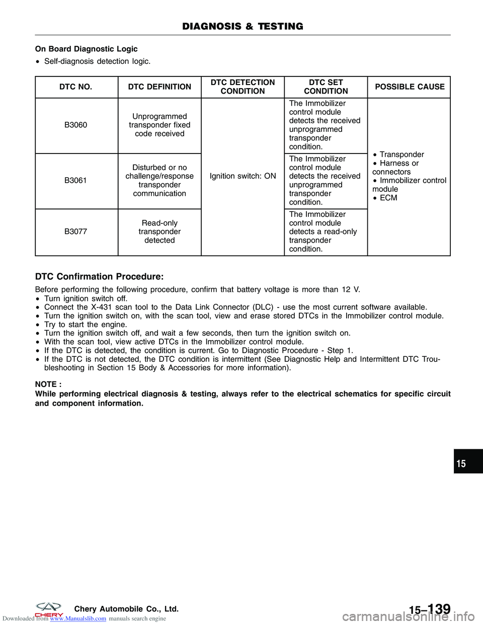
Downloaded from www.Manualslib.com manuals search engine On Board Diagnostic Logic
•Self-diagnosis detection logic.
DTC NO. DTC DEFINITION DTC DETECTION
CONDITION DTC SET
CONDITION POSSIBLE CAUSE
B3060 Unprogrammed
transponder fixed code received
Ignition switch: ON The Immobilizer
control module
detects the received
unprogrammed
transponder
condition.
•Transponder
• Harness or
connectors
• Immobilizer control
module
• ECM
B3061
Disturbed or no
challenge/response transponder
communication The Immobilizer
control module
detects the received
unprogrammed
transponder
condition.
B3077 Read-only
transponder detected The Immobilizer
control module
detects a read-only
transponder
condition.
DTC Confirmation Procedure:
Before performing the following procedure, confirm that battery voltage is more than 12 V.
•
Turn ignition switch off.
• Connect the X-431 scan tool to the Data Link Connector (DLC) - use the most current software available.
• Turn the ignition switch on, with the scan tool, view and erase stored DTCs in the Immobilizer control module.
• Try to start the engine.
• Turn the ignition switch off, and wait a few seconds, then turn the ignition switch on.
• With the scan tool, view active DTCs in the Immobilizer control module.
• If the DTC is detected, the condition is current. Go to Diagnostic Procedure - Step 1.
• If the DTC is not detected, the DTC condition is intermittent (See Diagnostic Help and Intermittent DTC Trou-
bleshooting in Section 15 Body & Accessories for more information).
NOTE :
While performing electrical diagnosis & testing, always refer to the electrical schematics for specific circuit
and component information.
DIAGNOSIS & TESTING
15
15–139Chery Automobile Co., Ltd.
Page 1724 of 1903
Downloaded from www.Manualslib.com manuals search engine Diagnostic Procedure
1.CHECK GROUND CONNECTION
• Turn ignition switch off.
• Loosen and retighten ground screws on the body (See Ground Inspection in Section 15 Body & Accessories).
• Inspect ground connection C-204 mounting position (See Vehicle Wiring Harness Layout - Main Harness in
Section 16 Wiring).
Is the ground connection OK?
Ye s>>Go to the next step.
No
>>Repair or replace ground connection.
2.CHECK IMMOBILIZER CONTROL MODULE DTC
• With the scan tool, view DTCs in the Immobilizer control module. Refer to DTC confirmation procedure.
Is DTC B3060, B3061 or B3077 present?
Ye s>>For DTC B3060, go to step 5.
For DTC B3061, go to the next step.
For DTC B3077, go to step 6.
No
>>The condition that caused the DTC is currently not present. Monitor the scan tool data relative to this
circuit while wiggle testing the wiring and connectors and looking for the DTC to reset. Using the wiring schematic as a guide, inspect the related wiring and connectors of the Immobilizer
control module.
Verify that there is good terminal contact in the related connectors.
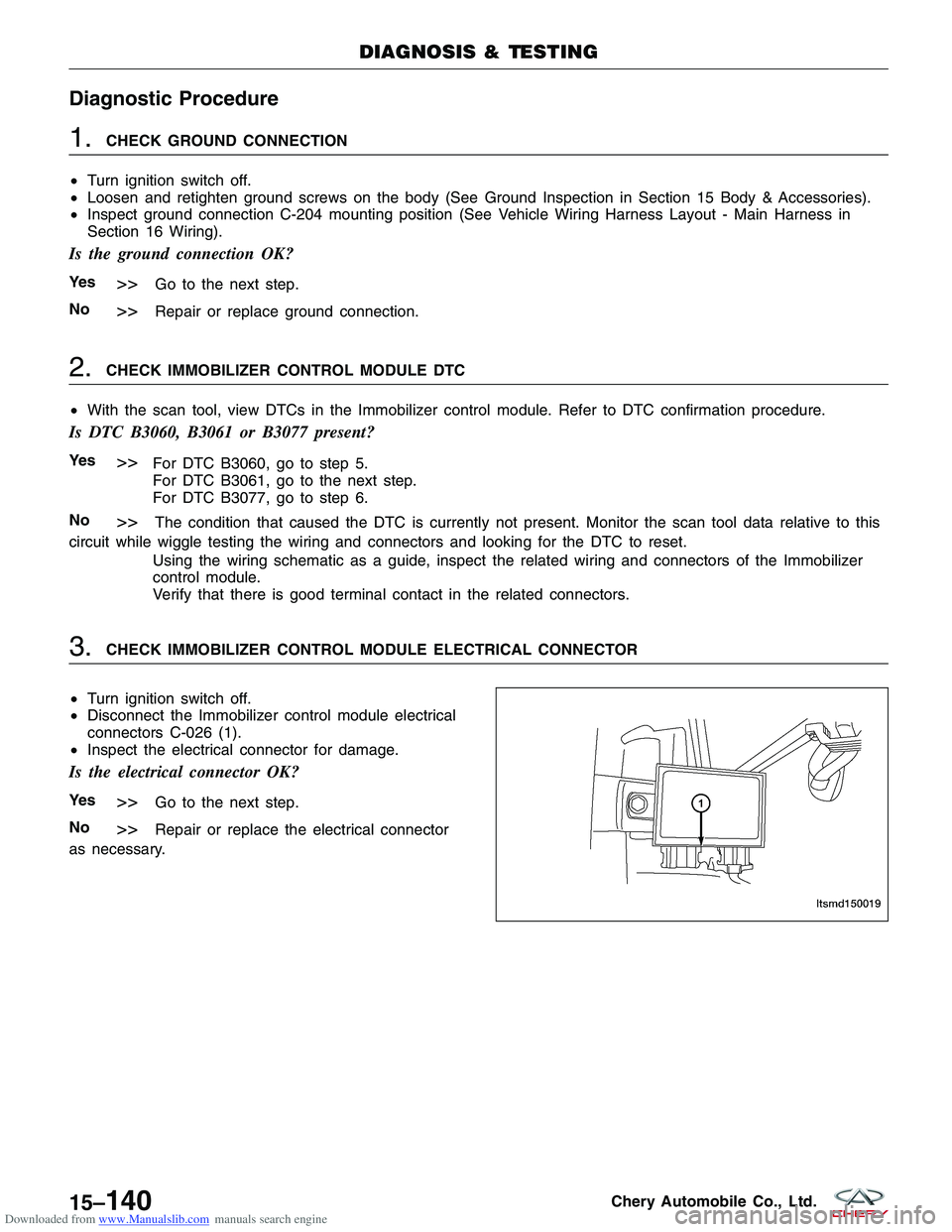
3.CHECK IMMOBILIZER CONTROL MODULE ELECTRICAL CONNECTOR
• Turn ignition switch off.
• Disconnect the Immobilizer control module electrical
connectors C-026 (1).
• Inspect the electrical connector for damage.
Is the electrical connector OK?
Ye s>>Go to the next step.
No
>>Repair or replace the electrical connector
as necessary.
DIAGNOSIS & TESTING
LTSMD150019
15–140Chery Automobile Co., Ltd.
Page 1726 of 1903
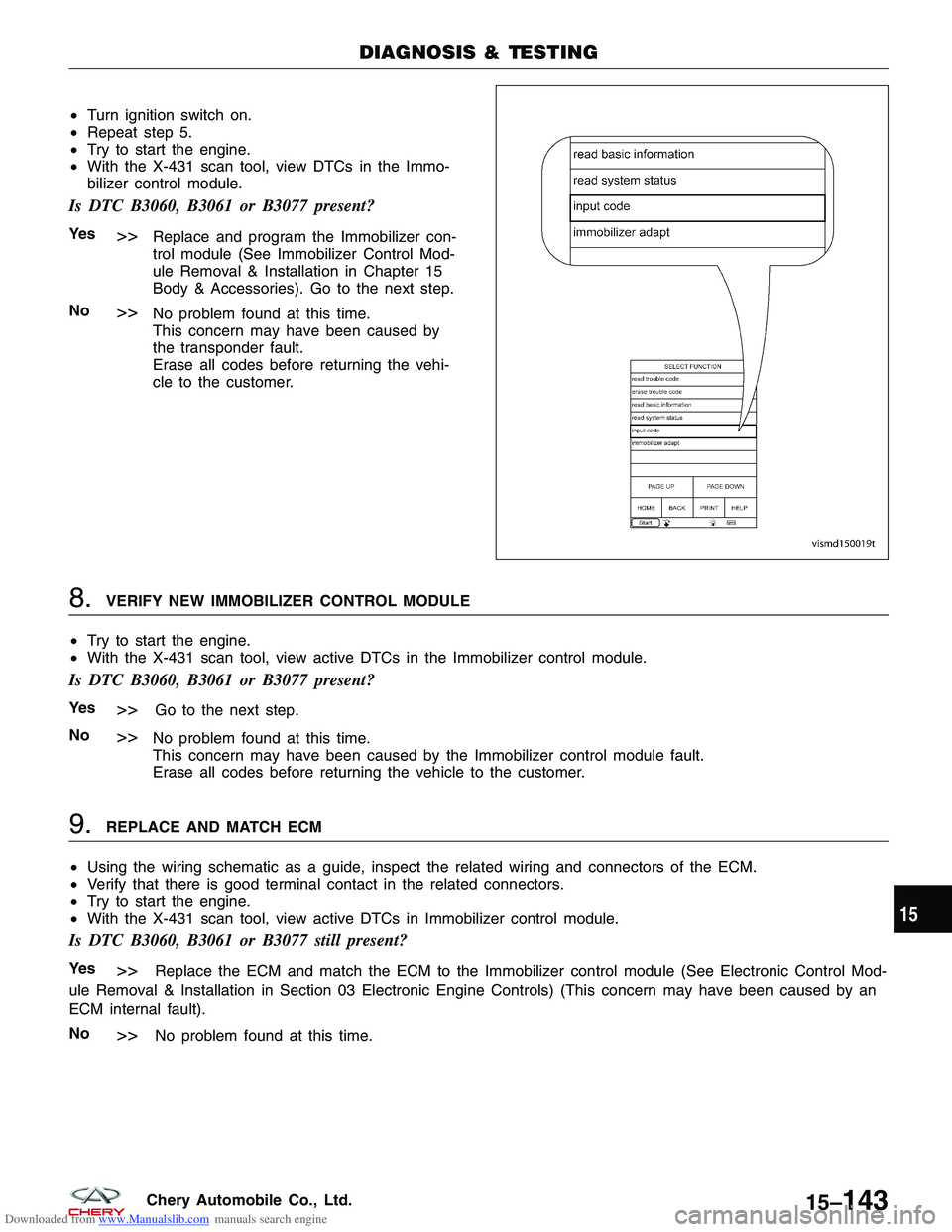
Downloaded from www.Manualslib.com manuals search engine 6.PROGRAM THE TRANSPONDER
• Turn ignition switch on.
• Using the X-431 scan tool, program the vehicle security system.
•
• Turn ignition switch on and perform the following:
� With the X-431 scan tool, choose T11 series.
� Choose �immobilize�.
� Input the safety code.
� Click the small keyboard.
� Click �OK�.
� Choose �Immobilizer adapt�.
� Choose �Key learning� immediately.
� Click �OK�.
• Try to start the engine.
• With the X-431 scan tool, view active DTCs in the Immobilizer control module.
Is DTC B3060, B3061 or B3077 present?
Ye s>>Go to the next step.
No
>>No problem found at this time.
This concern may have been caused by the not programmed transponder.
Erase all codes before returning the vehicle to the customer.
7.REPLACE AND PROGRAM THE TRANSPONDER
• Replace the chip (1) with a new one.
DIAGNOSIS & TESTING
VISMD150019T
VISMD150018
15–142Chery Automobile Co., Ltd.
Page 1727 of 1903
Downloaded from www.Manualslib.com manuals search engine •Turn ignition switch on.
• Repeat step 5.
• Try to start the engine.
• With the X-431 scan tool, view DTCs in the Immo-
bilizer control module.
Is DTC B3060, B3061 or B3077 present?
Ye s>>Replace and program the Immobilizer con-
trol module (See Immobilizer Control Mod-
ule Removal & Installation in Chapter 15
Body & Accessories). Go to the next step.
No
>>No problem found at this time.
This concern may have been caused by
the transponder fault.
Erase all codes before returning the vehi-
cle to the customer.
8.VERIFY NEW IMMOBILIZER CONTROL MODULE
• Try to start the engine.
• With the X-431 scan tool, view active DTCs in the Immobilizer control module.
Is DTC B3060, B3061 or B3077 present?
Ye s>>Go to the next step.
No
>>No problem found at this time.
This concern may have been caused by the Immobilizer control module fault.
Erase all codes before returning the vehicle to the customer.
9.REPLACE AND MATCH ECM
• Using the wiring schematic as a guide, inspect the related wiring and connectors of the ECM.
• Verify that there is good terminal contact in the related connectors.
• Try to start the engine.
• With the X-431 scan tool, view active DTCs in Immobilizer control module.
Is DTC B3060, B3061 or B3077 still present?
Ye s>>Replace the ECM and match the ECM to the Immobilizer control module (See Electronic Control Mod-
ule Removal & Installation in Section 03 Electronic Engine Controls) (This concern may have been caused by an
ECM internal fault).
No
>>No problem found at this time.
DIAGNOSIS & TESTING
VISMD150019T
15
15–143Chery Automobile Co., Ltd.
Page 1752 of 1903
Downloaded from www.Manualslib.com manuals search engine Front Door
Removal & Installation
1. Disconnect the negative battery cable.
2. Disconnect the inner harness electrical connectoron the front door.
3. Remove the mounting bolts (1) from the front door hinge.
4. Remove the front door assembly.
5. Installation is in the reverse order of removal.
Disassembly
1. Turn the ignition switch off.
2. Using a small trim stick, remove the pull handle cover (1) from the pull handle (2).
DOORS
LTSM150111
LTSM150139
15–168Chery Automobile Co., Ltd.
Page 1754 of 1903
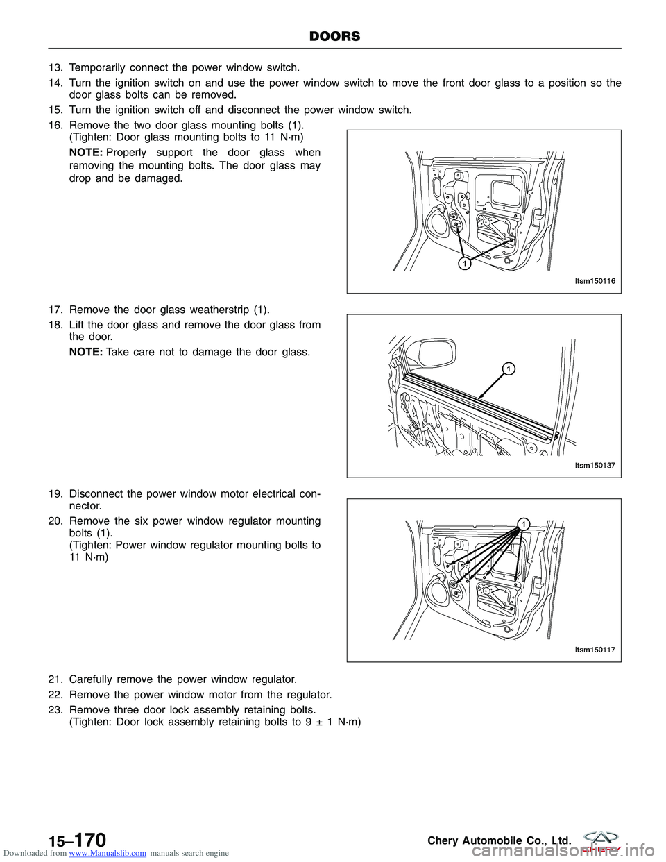
Downloaded from www.Manualslib.com manuals search engine 13. Temporarily connect the power window switch.
14. Turn the ignition switch on and use the power window switch to move the front door glass to a position so thedoor glass bolts can be removed.
15. Turn the ignition switch off and disconnect the power window switch.
16. Remove the two door glass mounting bolts (1). (Tighten: Door glass mounting bolts to 11 N·m)
NOTE: Properly support the door glass when
removing the mounting bolts. The door glass may
drop and be damaged.
17. Remove the door glass weatherstrip (1).
18. Lift the door glass and remove the door glass from the door.
NOTE: Take care not to damage the door glass.
19. Disconnect the power window motor electrical con- nector.
20. Remove the six power window regulator mounting bolts (1).
(Tighten: Power window regulator mounting bolts to
11 N·m)
21. Carefully remove the power window regulator.
22. Remove the power window motor from the regulator.
23. Remove three door lock assembly retaining bolts. (Tighten: Door lock assembly retaining bolts to9±1N·m)
DOORS
LTSM150116
LTSM150137 LTSM150117
15–170Chery Automobile Co., Ltd.
Page 1762 of 1903
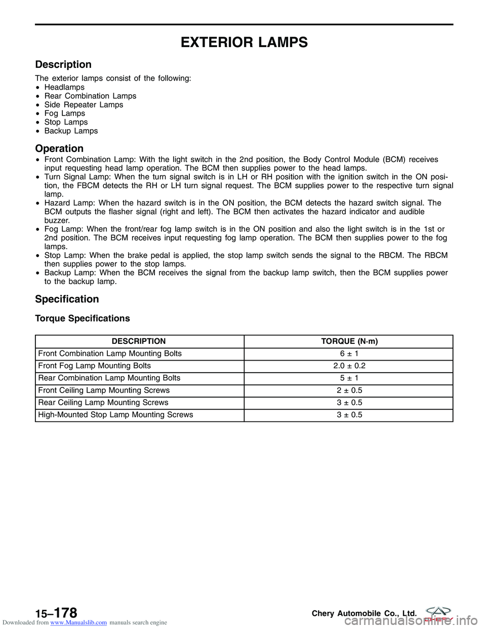
Downloaded from www.Manualslib.com manuals search engine EXTERIOR LAMPS
Description
The exterior lamps consist of the following:
•Headlamps
• Rear Combination Lamps
• Side Repeater Lamps
• Fog Lamps
• Stop Lamps
• Backup Lamps
Operation
•Front Combination Lamp: With the light switch in the 2nd position, the Body Control Module (BCM) receives
input requesting head lamp operation. The BCM then supplies power to the head lamps.
• Turn Signal Lamp: When the turn signal switch is in LH or RH position with the ignition switch in the ON posi-
tion, the FBCM detects the RH or LH turn signal request. The BCM supplies power to the respective turn signal
lamp.
• Hazard Lamp: When the hazard switch is in the ON position, the BCM detects the hazard switch signal. The
BCM outputs the flasher signal (right and left). The BCM then activates the hazard indicator and audible
buzzer.
• Fog Lamp: When the front/rear fog lamp switch is in the ON position and also the light switch is in the 1st or
2nd position. The BCM receives input requesting fog lamp operation. The BCM then supplies power to the fog
lamps.
• Stop Lamp: When the brake pedal is applied, the stop lamp switch sends the signal to the RBCM. The RBCM
then supplies power to the stop lamps.
• Backup Lamp: When the BCM receives the signal from the backup lamp switch, then the BCM supplies power
to the backup lamp.
Specification
Torque Specifications
DESCRIPTION TORQUE (N·m)
Front Combination Lamp Mounting Bolts 6 ± 1
Front Fog Lamp Mounting Bolts 2.0 ± 0.2
Rear Combination Lamp Mounting Bolts 5 ± 1
Front Ceiling Lamp Mounting Screws 2 ± 0.5
Rear Ceiling Lamp Mounting Screws 3 ± 0.5
High-Mounted Stop Lamp Mounting Screws 3 ± 0.5
15–178Chery Automobile Co., Ltd.
Page 1790 of 1903
Downloaded from www.Manualslib.com manuals search engine HORN
Description
A dual note electric horn system is installed on this vehicle. The horn system features electromagnetic horns. The
horn system includes the following components:
•Horn - The horns are located inside the left front bumper.
• Horn Switch - The horn switch is located under the driver airbag.
Operation
The horn system circuit is designed so that the system will remain operational, regardless of the ignition switch posi-
tion.
15–206Chery Automobile Co., Ltd.