Page 1664 of 1903

Downloaded from www.Manualslib.com manuals search engine On Board Diagnostic Logic
•Self-diagnosis detection logic.
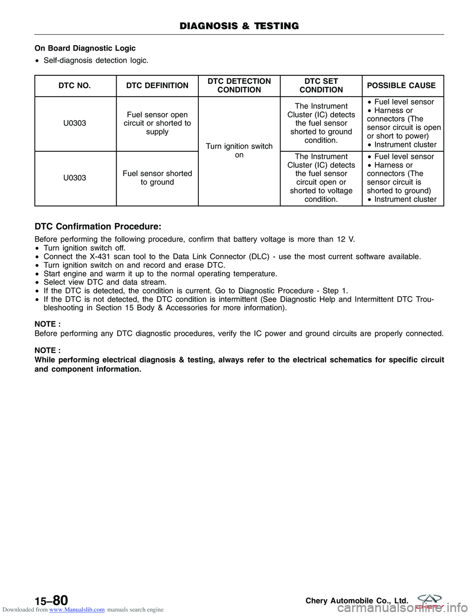
DTC NO. DTC DEFINITION DTC DETECTION
CONDITION DTC SET
CONDITION POSSIBLE CAUSE
U0303 Fuel sensor open
circuit or shorted to supply
Turn ignition switchon The Instrument
Cluster (IC) detects the fuel sensor
shorted to ground condition. •
Fuel level sensor
• Harness or
connectors (The
sensor circuit is open
or short to power)
• Instrument cluster
U0303 Fuel sensor shorted
to ground The Instrument
Cluster (IC) detects the fuel sensorcircuit open or
shorted to voltage condition. •
Fuel level sensor
• Harness or
connectors (The
sensor circuit is
shorted to ground)
• Instrument cluster
DTC Confirmation Procedure:
Before performing the following procedure, confirm that battery voltage is more than 12 V.
• Turn ignition switch off.
• Connect the X-431 scan tool to the Data Link Connector (DLC) - use the most current software available.
• Turn ignition switch on and record and erase DTC.
• Start engine and warm it up to the normal operating temperature.
• Select view DTC and data stream.
• If the DTC is detected, the condition is current. Go to Diagnostic Procedure - Step 1.
• If the DTC is not detected, the DTC condition is intermittent (See Diagnostic Help and Intermittent DTC Trou-
bleshooting in Section 15 Body & Accessories for more information).
NOTE :
Before performing any DTC diagnostic procedures, verify the IC power and ground circuits are properly connected.
NOTE :
While performing electrical diagnosis & testing, always refer to the electrical schematics for specific circuit
and component information.
DIAGNOSIS & TESTING
15–80Chery Automobile Co., Ltd.
Page 1665 of 1903

Downloaded from www.Manualslib.com manuals search engine Diagnostic Procedure
1.CHECK DTC
• Turn ignition switch on, with the scan tool, view and erase stored DTCs in the IC.
• Turn ignition switch off, and wait a few seconds, then turn ignition switch on.
• With the scan tool, view DTCs in the IC.
Is DTC U0303 present?
Ye s>>Go to the next step.
No
>>The conditions that caused this DTC to set are not present at this time (See Intermittent DTC Trouble-
shooting in Section 15 Body & Accessories for more information).
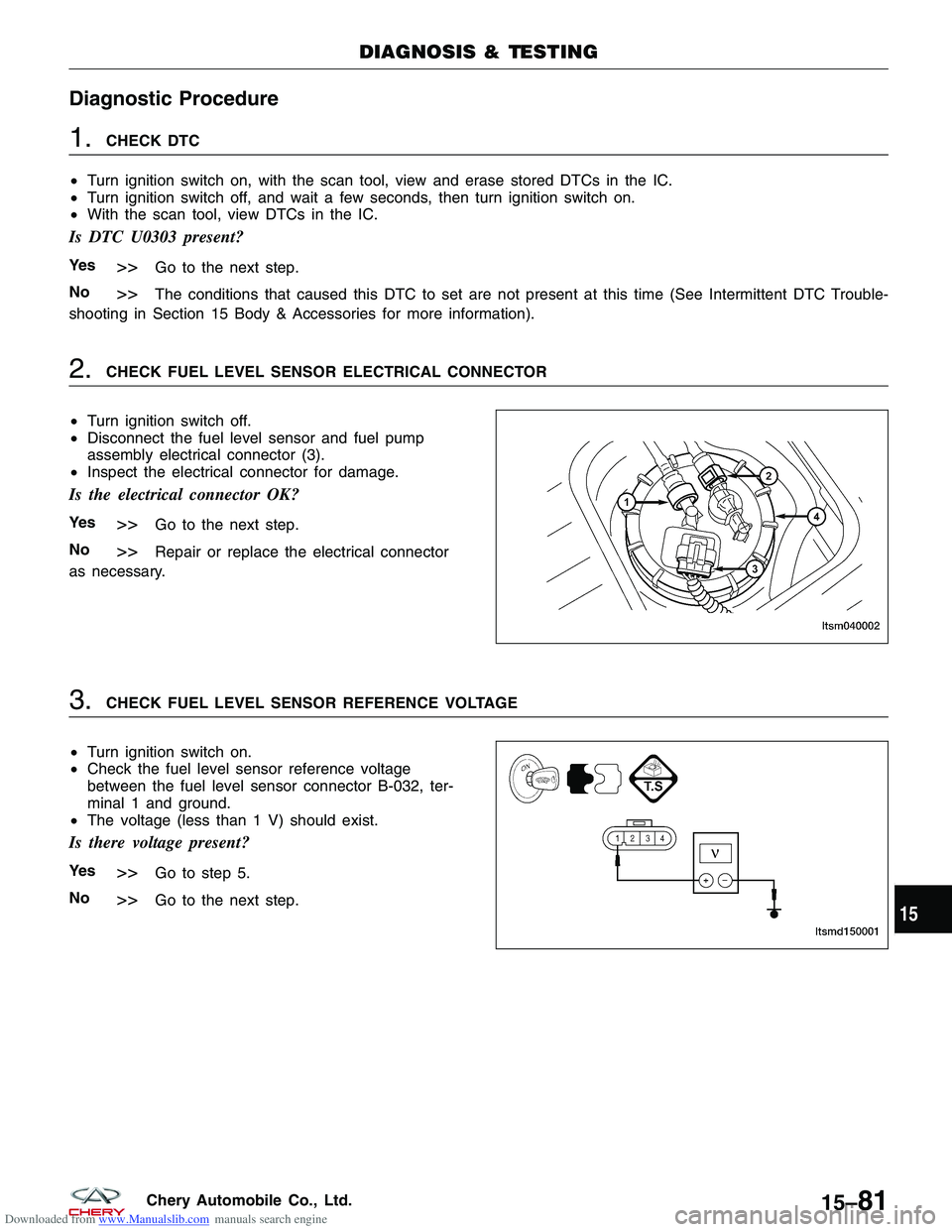
2.CHECK FUEL LEVEL SENSOR ELECTRICAL CONNECTOR
• Turn ignition switch off.
• Disconnect the fuel level sensor and fuel pump
assembly electrical connector (3).
• Inspect the electrical connector for damage.
Is the electrical connector OK?
Ye s>>Go to the next step.
No
>>Repair or replace the electrical connector
as necessary.
3.CHECK FUEL LEVEL SENSOR REFERENCE VOLTAGE
• Turn ignition switch on.
• Check the fuel level sensor reference voltage
between the fuel level sensor connector B-032, ter-
minal 1 and ground.
• The voltage (less than 1 V) should exist.
Is there voltage present?
Ye s>>Go to step 5.
No
>>Go to the next step.
DIAGNOSIS & TESTING
LTSM040002
LTSMD150001
15
15–81Chery Automobile Co., Ltd.
Page 1666 of 1903
Downloaded from www.Manualslib.com manuals search engine 4.CHECK FUEL LEVEL SENSOR CIRCUIT FOR OPEN OR SHORT
• Turn ignition switch off.
• Disconnect the IC connector.
• Check harness for a short to ground.
FUEL LEVEL SENSOR
TERMINAL GROUND
1
Ground
• Check for continuity between the following terminals:
FUEL LEVEL
SENSOR
TERMINAL IC TERMINAL CONTINUITY
12
1Yes
• Continuity should exist.
• Check the harness for a short to power.
Is the check result normal?
Ye s>>Go to the next step.
No
>>Repair or replace the fuel level sensor supply circuit as necessary.
5.CHECK FUEL LEVEL SENSOR GROUND CIRCUIT
• Using a 12 V test light connected to battery (+), probe fuel level sensor ground circuit.
Does the test light illuminate brightly?
Ye s>>Go to the next step.
No
>>Repair or replace the fuel level sensor ground circuit for an open.
DIAGNOSIS & TESTING
15–82Chery Automobile Co., Ltd.
Page 1667 of 1903
Downloaded from www.Manualslib.com manuals search engine 6.CHECK FUEL LEVEL SENSOR RESISTANCE
• Turn ignition switch off.
• Check fuel level sensor as follows:
FUEL GAUGE POINTER
POSITION TANK (LITERS)SENDER RESISTANCE
(OHM) POINTER TOLERANCE
EMPTY 5283 ±3 °
RESERVE 11189 ±3 °
1/4 16.5 137±3 °
1/2 2889±3 °
3/4 39.5 62±3 °
FULL 5140±3 °
Is the check result normal?
Ye s>>Go to the next step.
No
>>Replace the fuel level sensor.
7.CHECK DTC
• With the X-431 scan tool, read IC DTCs.
• Refer to �DTC Confirmation Procedure�.
Is the DTC U0303 still present?
Ye s>>Replace the IC.
No
>>The system is now operating properly.
Reassemble the vehicle and verify the customers complaint is repaired.
DIAGNOSIS & TESTING
15
15–83Chery Automobile Co., Ltd.
Page 1676 of 1903
Downloaded from www.Manualslib.com manuals search engine 2. Remove the lamp mounting screws (1).
3. Remove the courtesy/dome lamp.
NOTE :
The rear courtesy/dome lamp is similar to the middle courtesy/dome lamp. 4. Installation is in the reverse order of removal.
Key Hole Lamp
Removal & Installation
1. Disconnect the negative battery cable.
2. Turn the ignition switch off.
3. Remove the steering column shroud retaining screws (1).
4. Disconnect the key hole lamp electrical connector.
5. Remove the key hole lamp.
6. Installation is in the reverse order of removal.
INTERIOR LAMPS
LTSM150044
LTSM110031
15–92Chery Automobile Co., Ltd.
Page 1684 of 1903
Downloaded from www.Manualslib.com manuals search engine Power Window Switch
Removal & Installation
1. Turn the ignition switch off.
2. Remove the power window and door lock/unlockswitch bezel mounting screw (1).
3. Using a trim stick, pry out the power window and door lock/unlock switch assembly from the front door.
4. Disconnect the power window and door lock/unlock switch electrical connectors.
5. Remove the power window and door lock/unlock switch retaining screws to remove the power window and door lock/unlock switch.
6. Installation is in the reverse order of removal.
Power Window Motor
Removal & Installation
NOTE :
The passenger door is shown, all other doors are similar.
1. Turn the ignition switch off.
2. Using a small trim stick, remove the pull handle cover (1) from the pull handle (2).
POWER WINDOW
LTSM150097
LTSM150139
15–100Chery Automobile Co., Ltd.
Page 1686 of 1903

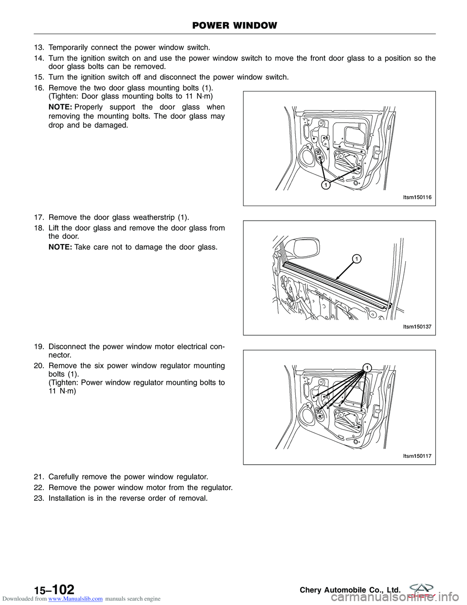
Downloaded from www.Manualslib.com manuals search engine 13. Temporarily connect the power window switch.
14. Turn the ignition switch on and use the power window switch to move the front door glass to a position so thedoor glass bolts can be removed.
15. Turn the ignition switch off and disconnect the power window switch.
16. Remove the two door glass mounting bolts (1). (Tighten: Door glass mounting bolts to 11 N·m)
NOTE: Properly support the door glass when
removing the mounting bolts. The door glass may
drop and be damaged.
17. Remove the door glass weatherstrip (1).
18. Lift the door glass and remove the door glass from the door.
NOTE: Take care not to damage the door glass.
19. Disconnect the power window motor electrical con- nector.
20. Remove the six power window regulator mounting bolts (1).
(Tighten: Power window regulator mounting bolts to
11 N·m)
21. Carefully remove the power window regulator.
22. Remove the power window motor from the regulator.
23. Installation is in the reverse order of removal.
POWER WINDOW
LTSM150116
LTSM150137 LTSM150117
15–102Chery Automobile Co., Ltd.
Page 1688 of 1903

Downloaded from www.Manualslib.com manuals search engine SEATS
General Information
Description
The seat movement is controlled by an adjustment bar. The seat can be adjusted to six different seating positions.
The vehicle may be equipped with heated seats. Heated seats provide comfort and warmth in cold weather. The
heaters provide the same heat level for both the seat cushion and back. The driver seat and front passenger seat are
heated.
Operation
The manual seat adjustment bar is at the front of the seat, near the floor. Pull the bar upward and slide the seat
forward or rearward. Release the bar once the seat is in the desired position. To confirm the seat is locked into place,
attempt to move the seat forward and rearward after adjusting the seat. The heated seat controls for each seat are
located near the bottom center of the instrument panel. After turning the ignition ON, the seat heater can be activated
to High or Low heat settings. When the switch is in the middle position, the seat heater is OFF. Each switch is
equipped with LED lights to indicate the level of heat at which each seat is set.
15–104Chery Automobile Co., Ltd.