Page 1708 of 1903

Downloaded from www.Manualslib.com manuals search engine 5.CHECK IMMOBILIZER CONTROL MODULE AND ECM COMMUNICATION CIRCUIT
• For DTC B3042, check the resistance of W-Line between the Immobilizer control module connector C-025, pin
8 and ground.
IMMOBILIZER
CONTROLMODULE
TERMINAL TERMINAL RESULT
8
Ground Continuity
should not exist
• For DTC B3043, turn ignition switch on, check voltage between the Immobilizer control module connector
C-025, pin 8 and ground.
IMMOBILIZER
CONTROLMODULE
TERMINAL TERMINAL RESULT
8
Ground12 V should not
exist
Is the check result normal?
Ye s>>Go to the next step.
No
>>Repair the circuits fault as necessary.
6.REPLACE AND PROGRAM THE IMMOBILIZER CONTROL MODULE
• Replace and program the Immobilizer control module with the X-431.
• Reconnect all disconnected electrical harness connectors.
• With the X-431 scan tool, view the DTCs in the Immobilizer control module.
Is DTC B3042 or B3043 present again?
Ye s>>Go to the next step.
No
>>The system is now operating properly.
The DTC was caused by Immobilizer control module.
DIAGNOSIS & TESTING
15–124Chery Automobile Co., Ltd.
Page 1711 of 1903

Downloaded from www.Manualslib.com manuals search engine On Board Diagnostic Logic
•Self-diagnosis detection logic.
DTC NO. DTC DEFINITION DTC DETECTION
CONDITION DTC SET
CONDITION POSSIBLE CAUSE
B3050 Relay external line
short circuit to
ground or open
circuit, relay external line malfunction Ignition switch: ON The Immobilizer
control module
detects a short to
ground condition on
the W-Line for at
least 3 seconds. •
Harness or
connectors
• Immobilizer control
module
B3053 Relay external line
short circuit to battery Ignition switch: ON The Immobilizer
control module
detects a short to
battery condition on
the relay external
line. •
Harness or
connectors
• Immobilizer control
module
DTC Confirmation Procedure:
Before performing the following procedure, confirm that battery voltage is more than 12 V.
• Turn ignition switch off.
• Connect the X-431 scan tool to the Data Link Connector (DLC) - use the most current software available.
• Turn ignition switch on, with the scan tool, view and erase stored DTCs in the Immobilizer control module.
• Try to start the engine.
• Turn ignition switch off, and wait a few seconds, then turn ignition switch on.
• With the scan tool, view active DTCs in the Immobilizer control module.
• If the DTC is detected, the condition is current. Go to Diagnostic Procedure - Step 1.
• If the DTC is not detected, the DTC condition is intermittent (See Diagnostic Help and Intermittent DTC Trou-
bleshooting in Section 15 Body & Accessories for more information).
NOTE :
While performing electrical diagnosis & testing, always refer to the electrical schematics for specific circuit
and component information.
DIAGNOSIS & TESTING
15
15–127Chery Automobile Co., Ltd.
Page 1712 of 1903

Downloaded from www.Manualslib.com manuals search engine Diagnostic Procedure
1.CHECK GROUND CONNECTION
• Turn ignition switch off.
• Loosen and retighten ground screws on the body (See Ground Inspection in Section 15 Body & Accessories).
• Inspect ground connection C-204 mounting position (See Vehicle Wiring Harness Layout - Main Harness in
Section 16 Wiring).
Is the ground connection OK?
Ye s>>Go to the next step.
No
>>Repair or replace ground connection.
2.CHECK IMMOBILIZER CONTROL MODULE DTC
• With the scan tool, view DTCs in the Immobilizer control module. Refer to DTC confirmation procedure.
Is DTC B3050 or B3053 present?
Ye s>>Go to the next step.
No
>>The condition that caused the DTC to set is currently not present (See Diagnosis & Testing Diagnostic
Help in Section 15 Body & Accessories).
3.CHECK IMMOBILIZER CONTROL MODULE ELECTRICAL CONNECTOR
• Turn ignition switch off.
• Disconnect the Immobilizer control module electrical
connectors C-025 (1).
• Inspect the electrical connector for damage.
Is the electrical connector OK?
Ye s>>Go to the next step.
No
>>Repair or replace the electrical connector
as necessary.
DIAGNOSIS & TESTING
LTSMD150019
15–128Chery Automobile Co., Ltd.
Page 1713 of 1903
Downloaded from www.Manualslib.com manuals search engine 4.CHECK IMMOBILIZER CONTROL MODULE POWER SUPPLY
• Turn ignition switch on.
• Check if voltage is present on the Immobilizer control module connector C-025, pin 4,1 and ground.
IMMOBILIZER CONTROL
MODULE TERMINAL GROUND
1
Ground
4
Is 12 V present?
Ye s>>Replace and program the Immobilizer control module. Refer to DTC B3077 Diagnostic Procedure.
No
>>For DTC B3050, go to the next step.
For DTC B3053, go to the step 6.
5.CHECK IMMOBILIZER CONTROL MODULE POWER SUPPLY CIRCUIT
• Turn ignition switch off.
• Disconnect the negative battery cable.
• Disconnect the body fuse and relay box electrical connector A.
• Check harness continuity between the following terminals:
• Continuity should exist.
BODY FUSE
AND RELAY BOX
TERMINAL IMMOBILIZER
CONTROLMODULE
TERMINAL CONTINUITY
A2
1Yes
DIAGNOSIS & TESTING
15
15–129Chery Automobile Co., Ltd.
Page 1714 of 1903

Downloaded from www.Manualslib.com manuals search engine •Check for harness continuity between the following terminals:
• Continuity should exist.
BODY FUSE
AND RELAY BOX
TERMINAL IMMOBILIZER
CONTROLMODULE
TERMINAL CONTINUITY
A6
4Yes
• Check harness for a short to ground.
• Continuity between Immobilizer control module power supply and ground should not exist.
Is the check result normal?
Ye s>>Go to the step 7.
No
>>Repair or replace the open or high resistance circuit or short to ground in harness or connectors.
6.CHECK IMMOBILIZER CONTROL MODULE POWER SUPPLY CIRCUIT
• Turn ignition switch off.
• Disconnect the negative battery cable.
• Disconnect the body fuse and relay box electrical connector A.
• Check the resistance between Immobilizer control module ignition switch circuit terminal 4 and Immobilizer con-
trol module battery supply circuit terminal 1.
IMMOBILIZER
CONTROLMODULE
TERMINAL IMMOBILIZER
CONTROLMODULE
TERMINAL CONTINUITY
14N
o
• Check resistance between Immobilizer control module ignition switch circuit and other power circuits.
Is the check result normal?
Ye s>>Go to the step 8.
No
>>Repair or replace short to power circuits in harness or connectors.
DIAGNOSIS & TESTING
15–130Chery Automobile Co., Ltd.
Page 1717 of 1903

Downloaded from www.Manualslib.com manuals search engine On Board Diagnostic Logic
•Self-diagnosis detection logic.
DTC NO. DTC DEFINITION DTC DETECTION
CONDITION DTC SET
CONDITION POSSIBLE CAUSE
B3055 No transponder
modulation or no transponder Ignition switch: ON The Immobilizer
control module
detects no
transponder or no
transponder
modulation
condition. •
Transponder
• Harness or
connectors
• Immobilizer control
module
B3056 No transponder
fixed code
programmed Ignition switch: ON The Immobilizer
control module
detects that the
transponder is not
programmed. •
Transponder
• Harness or
connectors
• Immobilizer control
module
DTC Confirmation Procedure:
Before performing the following procedure, confirm that battery voltage is more than 12 V.
• Turn ignition switch off.
• Connect the X-431 scan tool to the Data Link Connector (DLC) - use the most current software available.
• Turn the ignition switch on, with the scan tool, view and erase stored DTCs in the Immobilizer control module.
• Try to start the engine.
• Turn ignition switch off, and wait a few seconds, then turn the ignition switch on.
• With the scan tool, view active DTCs in the Immobilizer control module.
• If the DTC is detected, the condition is current. Go to Diagnostic Procedure - Step 1.
• If the DTC is not detected, the DTC condition is intermittent (See Diagnostic Help and Intermittent DTC Trou-
bleshooting in Section 15 Body & Accessories for more information).
NOTE :
While performing electrical diagnosis & testing, always refer to the electrical schematics for specific circuit
and component information.
Diagnostic Procedure
1.CHECK GROUND CONNECTION
• Turn ignition switch off.
• Loosen and retighten ground screws on the body (See Ground Inspection in Section 15 Body & Accessories).
• Inspect ground connection C-204 mounting position (See Vehicle Wiring Harness Layout - Main Harness in
Section 16 Wiring).
Is the ground connection OK?
Ye s>>Go to the next step.
No
>>Repair or replace ground connection.
2.CHECK IMMOBILIZER CONTROL MODULE DTC
• With the scan tool, view DTCs in the Immobilizer control module. Refer to DTC confirmation procedure.
Is DTC B3055 present?
Ye s>>Go to the next step.
No
>>The condition that caused the DTC to set is currently not present (See Diagnosis & Testing Diagnostic
Help in Section 15 Body & Accessories).
DIAGNOSIS & TESTING
15
15–133Chery Automobile Co., Ltd.
Page 1718 of 1903
Downloaded from www.Manualslib.com manuals search engine 3.CHECK IMMOBILIZER CONTROL MODULE ELECTRICAL CONNECTOR
• Turn ignition switch off.
• Disconnect the Immobilizer control module electrical
connectors C-026 (1).
• Inspect the electrical connector for damage.
Is the electrical connector OK?
Ye s>>Go to the next step.
No
>>Repair or replace the electrical connector
as necessary.
4.CHECK IMMOBILIZER COIL
• Check the resistance of the Immobilizer coil between the Immobilizer coil connector C-026, pin 9 and pin 11.
IMMOBILIZER COIL
TERMINAL IMMOBILIZER COIL
TERMINAL
91 1
Is the resistance range from 5 to 20 ohms?
Ye s>>Go to the next step.
No
>>Replace the Immobilizer coil.
DIAGNOSIS & TESTING
LTSMD150019
15–134Chery Automobile Co., Ltd.
Page 1720 of 1903
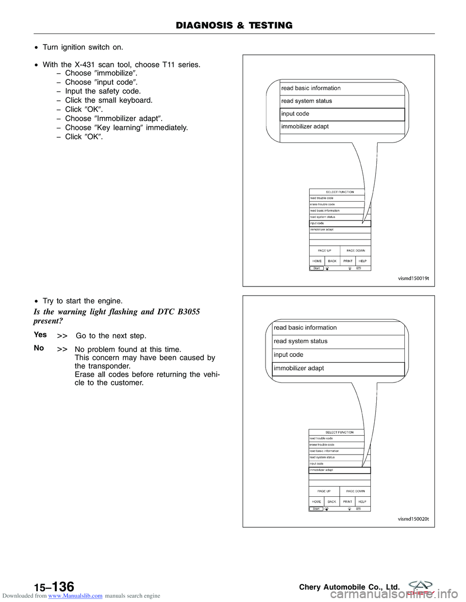
Downloaded from www.Manualslib.com manuals search engine •Turn ignition switch on.
• With the X-431 scan tool, choose T11 series.
� Choose �immobilize�.
� Choose �input code�.
� Input the safety code.
� Click the small keyboard.
� Click �OK�.
� Choose �Immobilizer adapt�.
� Choose �Key learning� immediately.
� Click �OK�.
• Try to start the engine.
Is the warning light flashing and DTC B3055
present?
Ye s>>Go to the next step.
No
>>No problem found at this time.
This concern may have been caused by
the transponder.
Erase all codes before returning the vehi-
cle to the customer.
DIAGNOSIS & TESTING
VISMD150019T
VISMD150020T
15–136Chery Automobile Co., Ltd.