Page 1809 of 1903
Downloaded from www.Manualslib.com manuals search engine The sunroof consists of the following components:
•Sunroof Frame (1)
• Windshield Frame (2)
• Sunroof Central Bracket (3)
• Sunroof Back Bracket (4)
• Rear Roof Frame (5)
• Head Liner (6)
• Sunroof Track (7)
• Sunroof Module (8)
• Sunroof Motor (9)
• Sunroof Deflector (10)
• Sunroof Glass (11)
• Guiding Gutter (12)
• Sun Visor (13)
Operation
The sunroof control module monitors the sunroof switch input. The sunroof control module controls the output of the
sunroof motor, to move the sunroof glass to the requested position. The power sunroof will operate with the ignition
switch turned to ON.
SUNROOF
15
15–225Chery Automobile Co., Ltd.
Page 1817 of 1903
Downloaded from www.Manualslib.com manuals search engine WIPERS AND WASHERS
Description
The wiper system operates the front and rear wipers. The windshield wiper system includes the following compo-
nents:
•Wiper and Washer Switch
• Front Wiper Motor
• Rear Wiper Motor
• Front Wiper Arm
• Rear Wiper Arm
• Front Wiper Link
• Washer Bottle
• Washer Pump
Operation
The wiper system is controlled by the wiper and washer switch. The wiper and washer system operate with the
ignition switch is in the ON position. All wiper and washer functions are controlled by rotating the control knob on the
end of the control stalk to the MIST, OFF, INT, LO or HI wiper positions.
15
15–233Chery Automobile Co., Ltd.
Page 1828 of 1903

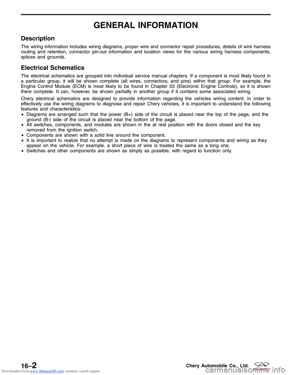
Downloaded from www.Manualslib.com manuals search engine GENERAL INFORMATION
Description
The wiring information includes wiring diagrams, proper wire and connector repair procedures, details of wire harness
routing and retention, connector pin-out information and location views for the various wiring harness components,
splices and grounds.
Electrical Schematics
The electrical schematics are grouped into individual service manual chapters. If a component is most likely found in
a particular group, it will be shown complete (all wires, connectors, and pins) within that group. For example, the
Engine Control Module (ECM) is most likely to be found in Chapter 03 (Electronic Engine Controls), so it is shown
there complete. It can, however, be shown partially in another group if it contains some associated wiring.
Chery electrical schematics are designed to provide information regarding the vehicles wiring content. In order to
effectively use the wiring diagrams to diagnose and repair Chery vehicles, it is important to understand the following
features and characteristics:
•Diagrams are arranged such that the power (B+) side of the circuit is placed near the top of the page, and the
ground (B-) side of the circuit is placed near the bottom of the page.
• All switches, components, and modules are shown in the at rest position with the doors closed and the key
removed from the ignition switch.
• Components are shown with a solid line around the component.
• It is important to realize that no attempt is made on the diagrams to represent components and wiring as they
appear on the vehicle. For example, a short piece of wire is treated the same as a long one.
• Switches and other components are shown as simply as possible, with regard to function only.
16–2Chery Automobile Co., Ltd.
Page 1831 of 1903

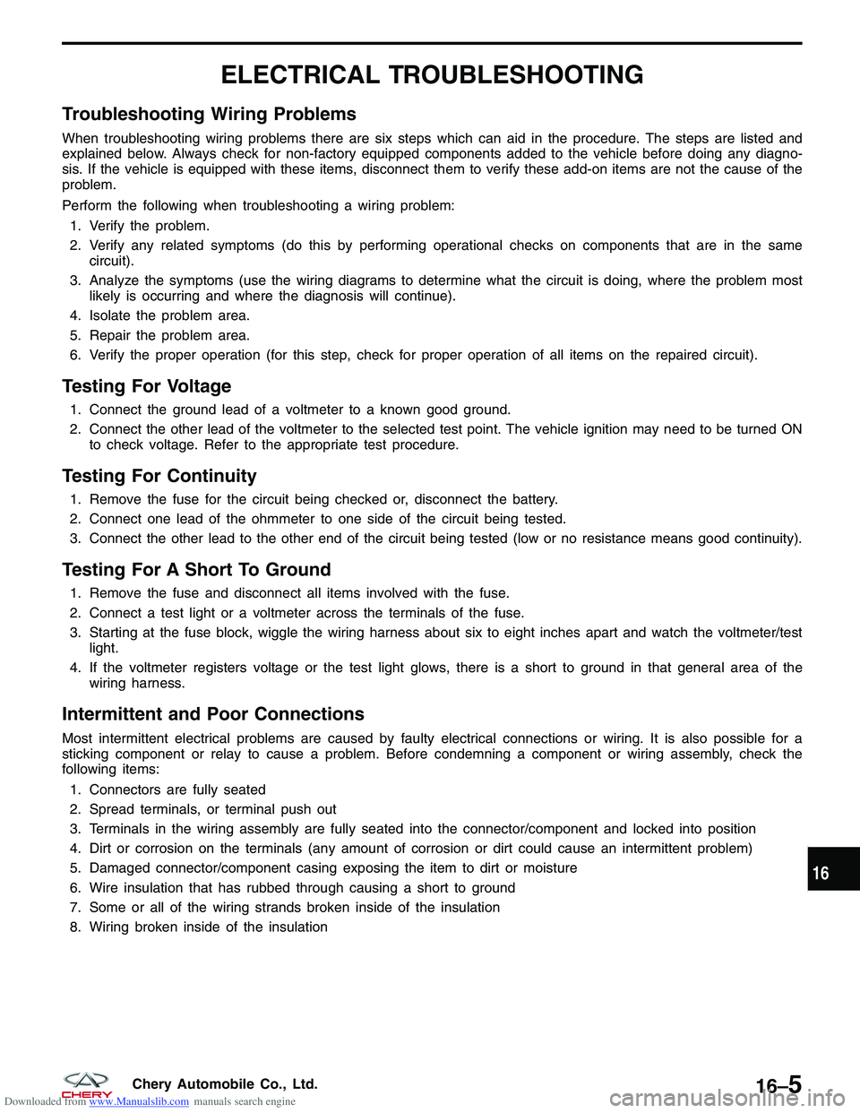
Downloaded from www.Manualslib.com manuals search engine ELECTRICAL TROUBLESHOOTING
Troubleshooting Wiring Problems
When troubleshooting wiring problems there are six steps which can aid in the procedure. The steps are listed and
explained below. Always check for non-factory equipped components added to the vehicle before doing any diagno-
sis. If the vehicle is equipped with these items, disconnect them to verify these add-on items are not the cause of the
problem.
Perform the following when troubleshooting a wiring problem:1. Verify the problem.
2. Verify any related symptoms (do this by performing operational checks on components that are in the same circuit).
3. Analyze the symptoms (use the wiring diagrams to determine what the circuit is doing, where the problem most likely is occurring and where the diagnosis will continue).
4. Isolate the problem area.
5. Repair the problem area.
6. Verify the proper operation (for this step, check for proper operation of all items on the repaired circuit).
Testing For Voltage
1. Connect the ground lead of a voltmeter to a known good ground.
2. Connect the other lead of the voltmeter to the selected test point. The vehicle ignition may need to be turned ON to check voltage. Refer to the appropriate test procedure.
Testing For Continuity
1. Remove the fuse for the circuit being checked or, disconnect the battery.
2. Connect one lead of the ohmmeter to one side of the circuit being tested.
3. Connect the other lead to the other end of the circuit being tested (low or no resistance means good continuity).
Testing For A Short To Ground
1. Remove the fuse and disconnect all items involved with the fuse.
2. Connect a test light or a voltmeter across the terminals of the fuse.
3. Starting at the fuse block, wiggle the wiring harness about six to eight inches apart and watch the voltmeter/testlight.
4. If the voltmeter registers voltage or the test light glows, there is a short to ground in that general area of the wiring harness.
Intermittent and Poor Connections
Most intermittent electrical problems are caused by faulty electrical connections or wiring. It is also possible for a
sticking component or relay to cause a problem. Before condemning a component or wiring assembly, check the
following items:
1. Connectors are fully seated
2. Spread terminals, or terminal push out
3. Terminals in the wiring assembly are fully seated into the connector/component and locked into position
4. Dirt or corrosion on the terminals (any amount of corrosion or dirt could cause an intermittent problem)
5. Damaged connector/component casing exposing the item to dirt or moisture
6. Wire insulation that has rubbed through causing a short to ground
7. Some or all of the wiring strands broken inside of the insulation
8. Wiring broken inside of the insulation
16
16–5Chery Automobile Co., Ltd.
Page 1839 of 1903
Downloaded from www.Manualslib.com manuals search engine GENERAL INFORMATION
Description
The power distribution system is designed to provide safe, reliable, centralized and convenient access to the distri-
bution of the electrical power required to operate all vehicle electrical and electronic systems.
The following components are used for power distribution:
•Battery
• Power Fuse Box
• Body Fuse and Relay Box
• Front Fuse and Relay Box
• Ignition Switch
• Fuses
• Circuit Breakers
• Relays
Operation
The power distribution system operates all electrical and electronic engine, transmission, chassis, safety, comfort and
convenience systems.
16
16–13Chery Automobile Co., Ltd.
Page 1866 of 1903
Downloaded from www.Manualslib.com manuals search engine Front Fuse and Relay Box
Description
The front fuse and relay box houses many of the fuses and relays for the vehicles electrical system. The front fuse
and relay box is located on the right side of the engine compartment and under the cowl top of windshield. If the
fuses and relays cannot be serviced, it must be replaced as a unit.
Operation
When a circuit fails, the fuse will blow and remove current from the circuit. The front fuse and relay box is equipped
with a label that identifies each component. The label is printed on the inside of the cover. The power fuse box
identifies the rating of each fuse individually. Turn off the ignition switch, and then replace the fuse.
GENERAL INFORMATION
16–40Chery Automobile Co., Ltd.
Page 1868 of 1903
Downloaded from www.Manualslib.com manuals search engine Body Fuse and Relay Box
Description
The body fuse and relay box houses many of the fuses and relays for the vehicle’s electrical system. The body fuse
and relay box is situated on the left front side of the interior of the cabin and under the instrument panel, which is
mounted on the cross beam of the instrument panel. All the fuses and relays cannot be serviced it must be replaced
as a unit.
Operation
When a circuit fails, the fuse will blow and remove current from the circuit.
Turn off the ignition switch, and then replace the fuse.
GENERAL INFORMATION
16–42Chery Automobile Co., Ltd.
Page 1875 of 1903

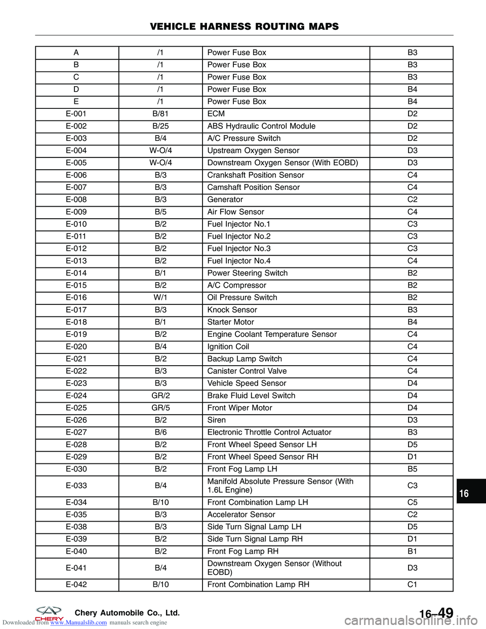
Downloaded from www.Manualslib.com manuals search engine A/1Power Fuse Box B3
B /1Power Fuse Box B3
C /1Power Fuse Box B3
D /1Power Fuse Box B4
E /1Power Fuse Box B4
E-001 B/81 ECM D2
E-002 B/25 ABS Hydraulic Control Module D2
E-003 B/4A/C Pressure Switch D2
E-004 W-O/4 Upstream Oxygen Sensor D3
E-005 W-O/4 Downstream Oxygen Sensor (With EOBD) D3
E-006 B/3Crankshaft Position Sensor C4
E-007 B/3Camshaft Position Sensor C4
E-008 B/3Generator C2
E-009 B/5Air Flow Sensor C4
E-010 B/2Fuel Injector No.1 C3
E-011 B/2Fuel Injector No.2 C3
E-012 B/2Fuel Injector No.3 C3
E-013 B/2Fuel Injector No.4 C4
E-014 B/1Power Steering Switch B2
E-015 B/2A/C Compressor B2
E-016 W/1 Oil Pressure Switch B2
E-017 B/3Knock Sensor B3
E-018 B/1Starter Motor B4
E-019 B/2Engine Coolant Temperature Sensor C4
E-020 B/4Ignition Coil C4
E-021 B/2Backup Lamp Switch C4
E-022 B/3Canister Control Valve C4
E-023 B/3Vehicle Speed Sensor D4
E-024 GR/2 Brake Fluid Level Switch D4
E-025 GR/5 Front Wiper Motor D4
E-026 B/2Siren D3
E-027 B/6Electronic Throttle Control Actuator B3
E-028 B/2Front Wheel Speed Sensor LH D5
E-029 B/2Front Wheel Speed Sensor RH D1
E-030 B/2Front Fog Lamp LH B5
E-033 B/4Manifold Absolute Pressure Sensor (With
1.6L Engine) C3
E-034 B/10 Front Combination Lamp LH C5
E-035 B/3Accelerator Sensor C2
E-038 B/3Side Turn Signal Lamp LH D5
E-039 B/2Side Turn Signal Lamp RH D1
E-040 B/2Front Fog Lamp RH B1
E-041 B/4Downstream Oxygen Sensor (Without
EOBD) D3
E-042 B/10 Front Combination Lamp RH C1
VEHICLE HARNESS ROUTING MAPS
16
16–49Chery Automobile Co., Ltd.