Page 1034 of 1903
Downloaded from www.Manualslib.com manuals search engine 5.CHECK EVM SOLENOID VALVE CONTROL CIRCUIT
• Turn ignition switch off.
• Disconnect TCM connector.
• Turn ignition switch on.
• Check if voltage is present between E-037, terminal B8 and ground.
• Check the harness for short to power supply circuits.
Is the check results normal?
Ye s>>Go to the next step.
No
>>Repair or replace the open circuit or short to ground or short to power supply in harness or connec-
tors.
6.CHECK EVM SIGNAL
• Connect TCM and EVM connector.
• With the engine running, move the shifter to �N�position, check the voltage of the EVM valve between the
TCM pin 26 and pin 19.
Is the voltage approximately 2.5 V with the engine running and the transaxle in the �N�position?
Ye s>>Go to the next step.
No
>>Go to step 8.
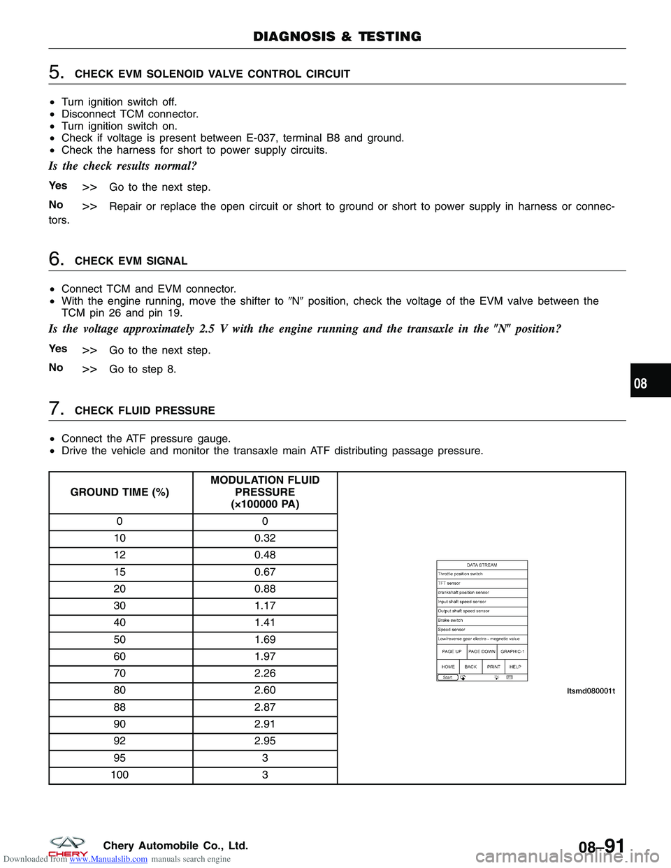
7.CHECK FLUID PRESSURE
• Connect the ATF pressure gauge.
• Drive the vehicle and monitor the transaxle main ATF distributing passage pressure.
GROUND TIME (%) MODULATION FLUID
PRESSURE
(×100000 PA)
00
10 0.32
12 0.48
15 0.67
20 0.88
30 1.17
40 1.41
50 1.69
60 1.97
70 2.26
80 2.60
88 2.87
90 2.91
92 2.95
95 3
100 3
DIAGNOSIS & TESTING
08
08–91Chery Automobile Co., Ltd.
Page 1035 of 1903
Downloaded from www.Manualslib.com manuals search engine •Verify if the EVM valve duty cycle and ATF pres-
sure ratio matches.
Does the EVM valve duty cycle and ATF pressure
ratio match?
Ye s>>Go to the next step.
No
>>Replace the EVM valve for a mechanical
problem or repair the transaxle internal main ATF dis-
tributing passage pressure control device.
8.CHECK DTC
• With the X-431 scan tool, read TCM DTCs.
• Refer to �DTC Confirmation Procedure�.
Is DTC P0775 present?
Ye s>>Replace the TCM.
No
>>The system is now operating properly.
Reassemble the vehicle and road test to verify the customers complaint is repaired.
DIAGNOSIS & TESTING
LTSMD080057
08–92Chery Automobile Co., Ltd.
Page 1038 of 1903
Downloaded from www.Manualslib.com manuals search engine Diagnostic Procedure
1.CHECK A/T SOLENOID SIGNAL
• With the scan tool, select view DTC and data stream for A/T.
• Start the engine.
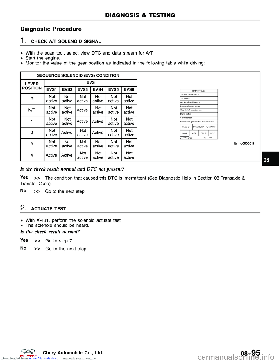
• Monitor the value of the gear position as indicated in the following table while driving:
SEQUENCE SOLENOID (EVS) CONDITION
LEVER
POSITION EVS
EVS1 EVS2 EVS3 EVS4 EVS5 EVS6
R Not
active Not
active Not
active Not
active Not
active Not
active
N/P Not
active Not
active Active Not
active Not
active Not
active
1 Not
active Not
active Active Active Not
active Not
active
2 Not
active Active Not
active Active Not
active Not
active
3 Not
active Not
active Not
active Not
active Not
active Not
active
4 Active Active Not
active Not
active Not
active Not
active
Is the check result normal and DTC not present?
Ye s>>The condition that caused this DTC is intermittent (See Diagnostic Help in Section 08 Transaxle &
Transfer Case).
No
>>Go to the next step.
2.ACTUATE TEST
• With X-431, perform the solenoid actuate test.
• The solenoid should be heard.
Is the check result normal?
Ye s>>Go to step 7.
No
>>Go to the next step.
DIAGNOSIS & TESTING
08
08–95Chery Automobile Co., Ltd.
Page 1039 of 1903
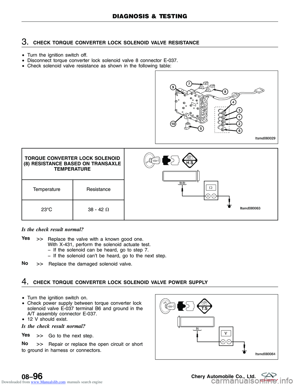
Downloaded from www.Manualslib.com manuals search engine 3.CHECK TORQUE CONVERTER LOCK SOLENOID VALVE RESISTANCE
• Turn the ignition switch off.
• Disconnect torque converter lock solenoid valve 8 connector E-037.
• Check solenoid valve resistance as shown in the following table:
TORQUE CONVERTER LOCK SOLENOID
(8) RESISTANCE BASED ON TRANSAXLE TEMPERATURE
Temperature Resistance
23°C 38 - 42�
Is the check result normal?
Ye s>>Replace the valve with a known good one.
With X-431, perform the solenoid actuate test.
� If the solenoid can be heard, go to step 7.
� If the solenoid can’t be heard, go to the next step.
No
>>Replace the damaged solenoid valve.
4.CHECK TORQUE CONVERTER LOCK SOLENOID VALVE POWER SUPPLY
• Turn the ignition switch on.
• Check power supply between torque converter lock
solenoid valve E-037 terminal B6 and ground in the
A/T assembly connector E-037.
• 12 V should exist.
Is the check result normal?
Ye s>>Go to the next step.
No
>>Repair or replace the open circuit or short
to ground in harness or connectors.
DIAGNOSIS & TESTING
LTSMD080029
LTSMD080064
08–96Chery Automobile Co., Ltd.
Page 1040 of 1903
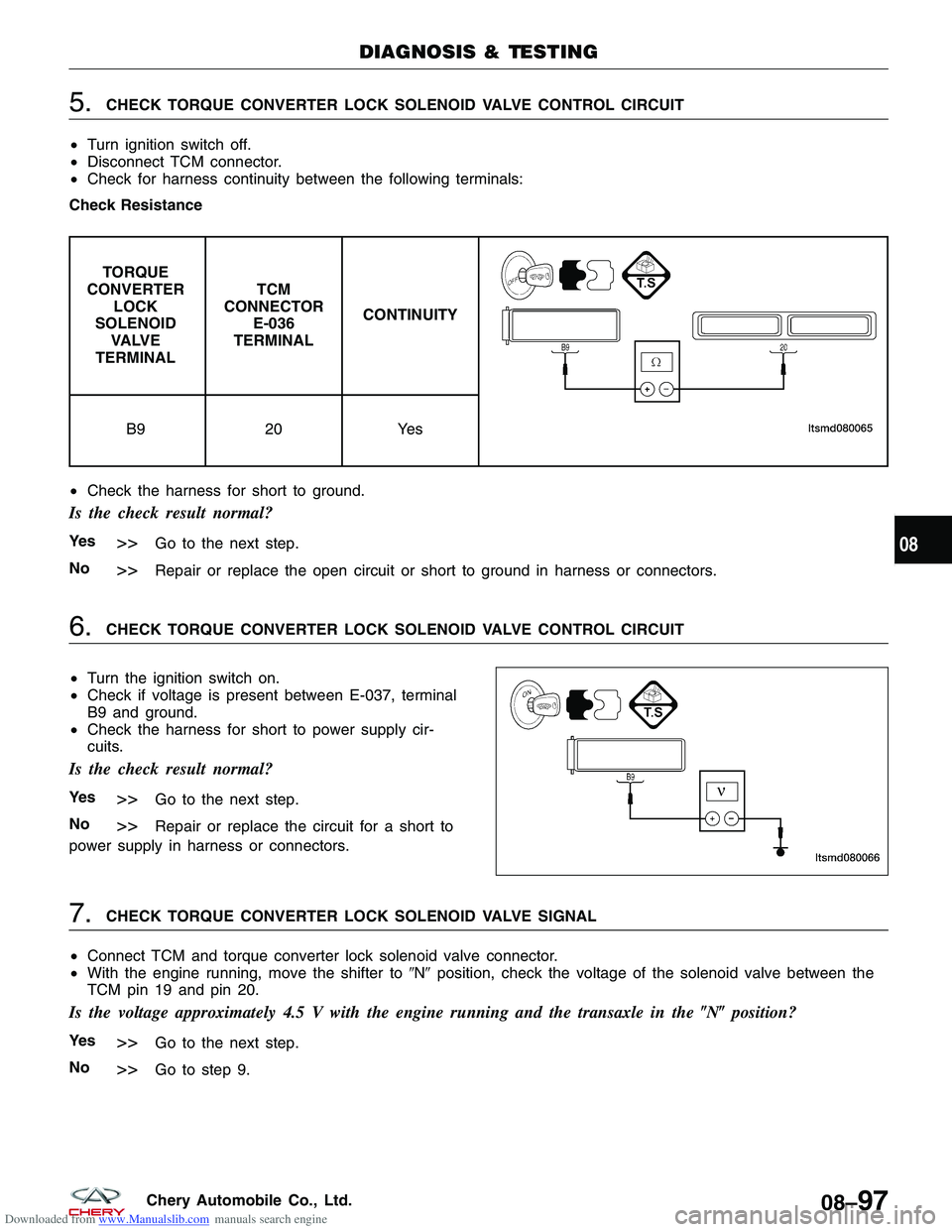
Downloaded from www.Manualslib.com manuals search engine 5.CHECK TORQUE CONVERTER LOCK SOLENOID VALVE CONTROL CIRCUIT
• Turn ignition switch off.
• Disconnect TCM connector.
• Check for harness continuity between the following terminals:
Check Resistance
TORQUE
CONVERTER LOCK
SOLENOID VA LV E
TERMINAL TCM
CONNECTOR E-036
TERMINAL CONTINUITY
B9
20Yes
• Check the harness for short to ground.
Is the check result normal?
Ye s>>Go to the next step.
No
>>Repair or replace the open circuit or short to ground in harness or connectors.
6.CHECK TORQUE CONVERTER LOCK SOLENOID VALVE CONTROL CIRCUIT
• Turn the ignition switch on.
• Check if voltage is present between E-037, terminal
B9 and ground.
• Check the harness for short to power supply cir-
cuits.
Is the check result normal?
Ye s>>Go to the next step.
No
>>Repair or replace the circuit for a short to
power supply in harness or connectors.
7.CHECK TORQUE CONVERTER LOCK SOLENOID VALVE SIGNAL
• Connect TCM and torque converter lock solenoid valve connector.
• With the engine running, move the shifter to �N�position, check the voltage of the solenoid valve between the
TCM pin 19 and pin 20.
Is the voltage approximately 4.5 V with the engine running and the transaxle in the �N�position?
Ye s>>Go to the next step.
No
>>Go to step 9.
DIAGNOSIS & TESTING
LTSMD080066
08
08–97Chery Automobile Co., Ltd.
Page 1041 of 1903
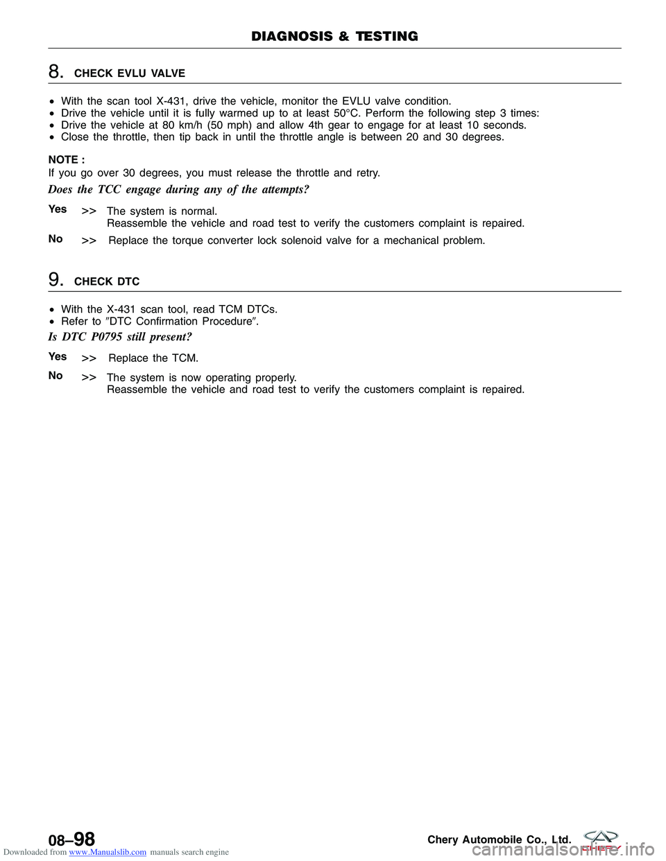
Downloaded from www.Manualslib.com manuals search engine 8.CHECK EVLU VALVE
• With the scan tool X-431, drive the vehicle, monitor the EVLU valve condition.
• Drive the vehicle until it is fully warmed up to at least 50°C. Perform the following step 3 times:
• Drive the vehicle at 80 km/h (50 mph) and allow 4th gear to engage for at least 10 seconds.
• Close the throttle, then tip back in until the throttle angle is between 20 and 30 degrees.
NOTE :
If you go over 30 degrees, you must release the throttle and retry.
Does the TCC engage during any of the attempts?
Ye s>>The system is normal.
Reassemble the vehicle and road test to verify the customers complaint is repaired.
No
>>Replace the torque converter lock solenoid valve for a mechanical problem.
9.CHECK DTC
• With the X-431 scan tool, read TCM DTCs.
• Refer to �DTC Confirmation Procedure�.
Is DTC P0795 still present?
Ye s>>Replace the TCM.
No
>>The system is now operating properly.
Reassemble the vehicle and road test to verify the customers complaint is repaired.
DIAGNOSIS & TESTING
08–98Chery Automobile Co., Ltd.
Page 1044 of 1903
Downloaded from www.Manualslib.com manuals search engine Diagnostic Procedure
1.CHECK A/T FLUID PRESSURE SENSOR SIGNAL
• With the scan tool, select view DTC and data stream for A/T.
• Start vehicle and monitor the value of �INPUT SPEED SENSOR�.
ITEM CONDITIONDISPLAY
VALUE
Fluid Pressure Ignition switch
on, not running
Below 0.2 bar
• Engine: Idle
• TFT: 31°C
• ECT: 30°C Approximately
0.05 bar
Is the check result normal?
Ye s>>The condition that caused this DTC is intermittent (See Diagnostic Help in Section 08 Transaxle &
Transfer Case).
No
>>Go to the next step.
2.CHECK FLUID PRESSURE SENSOR ELECTRICAL CONNECTOR
• Stop vehicle and turn ignition switch off.
• Disconnect fluid pressure sensor 2 connector.
• Inspect the electrical connector for damage.
Is the electrical connector OK?
Ye s>>Go to the next step.
No
>>Repair or replace the electrical connector
as necessary.
DIAGNOSIS & TESTING
LTSMD080021
08
08–101Chery Automobile Co., Ltd.
Page 1045 of 1903
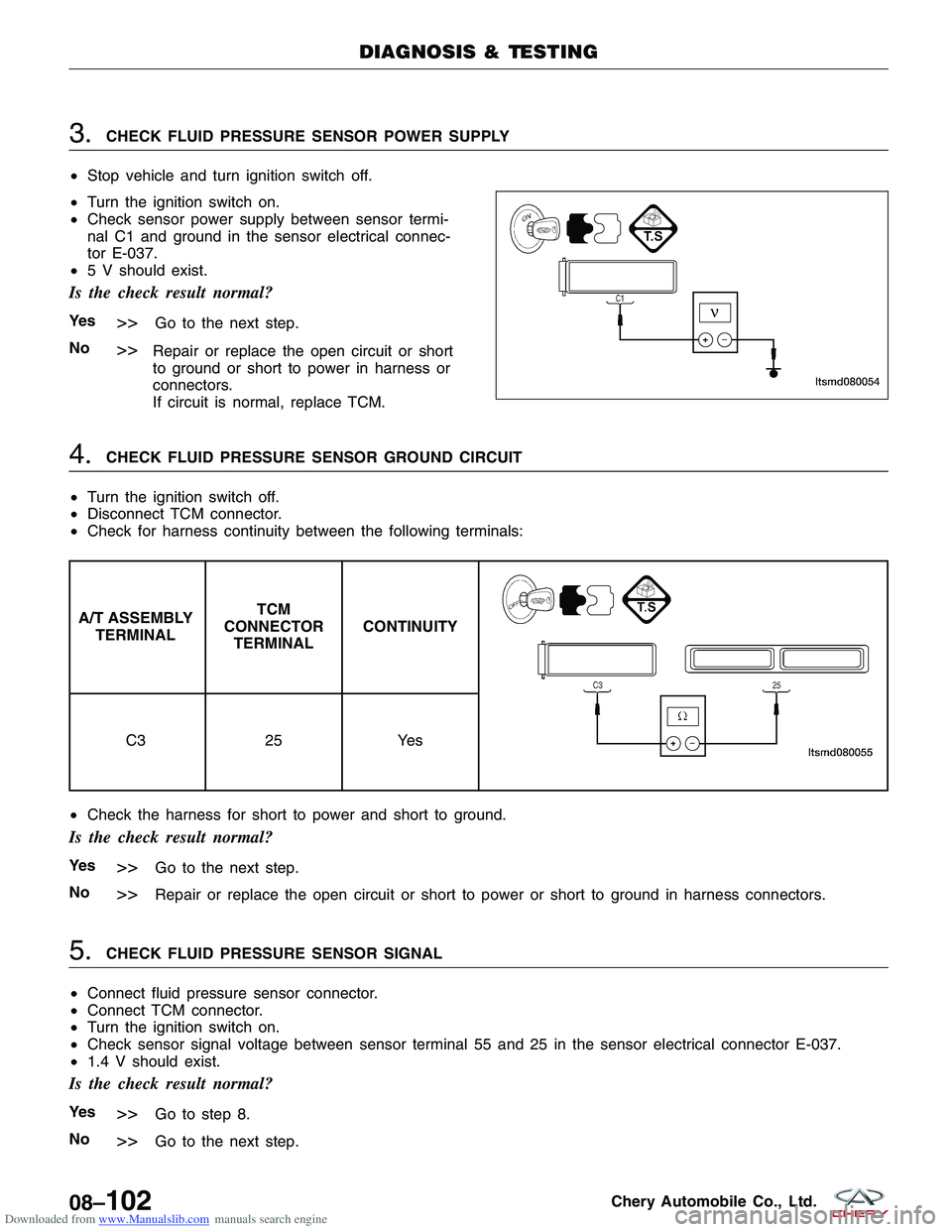
Downloaded from www.Manualslib.com manuals search engine 3.CHECK FLUID PRESSURE SENSOR POWER SUPPLY
• Stop vehicle and turn ignition switch off.
• Turn the ignition switch on.
• Check sensor power supply between sensor termi-
nal C1 and ground in the sensor electrical connec-
tor E-037.
• 5 V should exist.
Is the check result normal?
Ye s>>Go to the next step.
No
>>Repair or replace the open circuit or short
to ground or short to power in harness or
connectors.
If circuit is normal, replace TCM.
4.CHECK FLUID PRESSURE SENSOR GROUND CIRCUIT
• Turn the ignition switch off.
• Disconnect TCM connector.
• Check for harness continuity between the following terminals:
A/T ASSEMBLY
TERMINAL TCM
CONNECTOR TERMINAL CONTINUITY
C3
25Yes
• Check the harness for short to power and short to ground.
Is the check result normal?
Ye s>>Go to the next step.
No
>>Repair or replace the open circuit or short to power or short to ground in harness connectors.
5.CHECK FLUID PRESSURE SENSOR SIGNAL
• Connect fluid pressure sensor connector.
• Connect TCM connector.
• Turn the ignition switch on.
• Check sensor signal voltage between sensor terminal 55 and 25 in the sensor electrical connector E-037.
• 1.4 V should exist.
Is the check result normal?
Ye s>>Go to step 8.
No
>>Go to the next step.
DIAGNOSIS & TESTING
LTSMD080054
08–102Chery Automobile Co., Ltd.