2009 CHERY TIGGO engine
[x] Cancel search: enginePage 1417 of 1903
Downloaded from www.Manualslib.com manuals search engine Rotor Runout
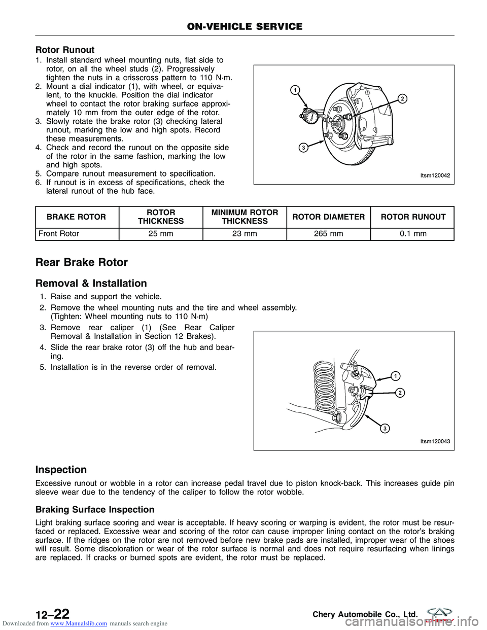
1. Install standard wheel mounting nuts, flat side torotor, on all the wheel studs (2). Progressively
tighten the nuts in a crisscross pattern to 110 N·m.
2. Mount a dial indicator (1), with wheel, or equiva- lent, to the knuckle. Position the dial indicator
wheel to contact the rotor braking surface approxi-
mately 10 mm from the outer edge of the rotor.
3. Slowly rotate the brake rotor (3) checking lateral runout, marking the low and high spots. Record
these measurements.
4. Check and record the runout on the opposite side of the rotor in the same fashion, marking the low
and high spots.
5. Compare runout measurement to specification.
6. If runout is in excess of specifications, check the lateral runout of the hub face.
BRAKE ROTOR ROTOR
THICKNESS MINIMUM ROTOR
THICKNESS ROTOR DIAMETER ROTOR RUNOUT
Front Rotor 25 mm23 mm265 mm 0.1 mm
Rear Brake Rotor
Removal & Installation
1. Raise and support the vehicle.
2. Remove the wheel mounting nuts and the tire and wheel assembly.
(Tighten: Wheel mounting nuts to 110 N·m)
3. Remove rear caliper (1) (See Rear Caliper Removal & Installation in Section 12 Brakes).
4. Slide the rear brake rotor (3) off the hub and bear- ing.
5. Installation is in the reverse order of removal.
Inspection
Excessive runout or wobble in a rotor can increase pedal travel due to piston knock-back. This increases guide pin
sleeve wear due to the tendency of the caliper to follow the rotor wobble.
Braking Surface Inspection
Light braking surface scoring and wear is acceptable. If heavy scoring or warping is evident, the rotor must be resur-
faced or replaced. Excessive wear and scoring of the rotor can cause improper lining contact on the rotor’s braking
surface. If the ridges on the rotor are not removed before new brake pads are installed, improper wear of the shoes
will result. Some discoloration or wear of the rotor surface is normal and does not require resurfacing when linings
are replaced. If cracks or burned spots are evident, the rotor must be replaced.
ON-VEHICLE SERVICE
LTSM120042
LTSM120043
12–22Chery Automobile Co., Ltd.
Page 1418 of 1903
Downloaded from www.Manualslib.com manuals search engine Rotor Minimum Thickness
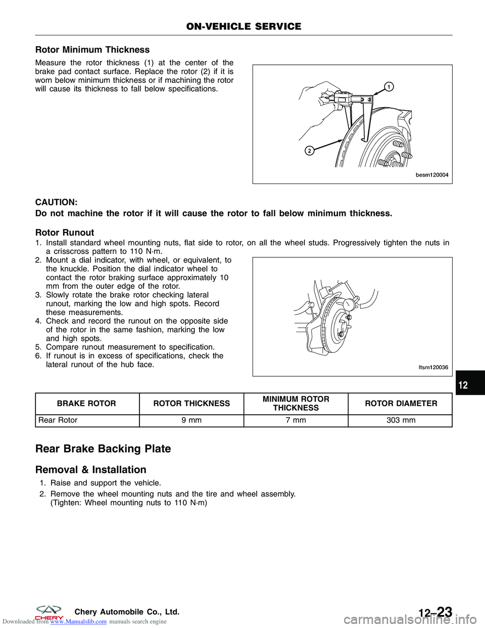
Measure the rotor thickness (1) at the center of the
brake pad contact surface. Replace the rotor (2) if it is
worn below minimum thickness or if machining the rotor
will cause its thickness to fall below specifications.
CAUTION:
Do not machine the rotor if it will cause the rotor to fall below minimum thickness.
Rotor Runout
1. Install standard wheel mounting nuts, flat side to rotor, on all the wheel studs. Progressively tighten the nuts ina crisscross pattern to 110 N·m.
2. Mount a dial indicator, with wheel, or equivalent, to the knuckle. Position the dial indicator wheel to
contact the rotor braking surface approximately 10
mm from the outer edge of the rotor.
3. Slowly rotate the brake rotor checking lateral runout, marking the low and high spots. Record
these measurements.
4. Check and record the runout on the opposite side of the rotor in the same fashion, marking the low
and high spots.
5. Compare runout measurement to specification.
6. If runout is in excess of specifications, check the lateral runout of the hub face.
BRAKE ROTOR ROTOR THICKNESS MINIMUM ROTOR
THICKNESS ROTOR DIAMETER
Rear Rotor 9 mm7 mm303 mm
Rear Brake Backing Plate
Removal & Installation
1. Raise and support the vehicle.
2. Remove the wheel mounting nuts and the tire and wheel assembly.
(Tighten: Wheel mounting nuts to 110 N·m)
ON-VEHICLE SERVICE
BESM120004
LTSM120036
12
12–23Chery Automobile Co., Ltd.
Page 1419 of 1903
Downloaded from www.Manualslib.com manuals search engine 3. Remove the rear brake caliper (See Rear BrakeCaliper Removal & Installation in Section 12
Brake).
4. Remove the rear brake rotor (See Rear Brake Rotor Removal & Installation in Section 12 Brake).
5. Remove the rear hub and bearing (See Rear Hub And Bearing Removal & Installation in Section 09
Driveline & Axle).
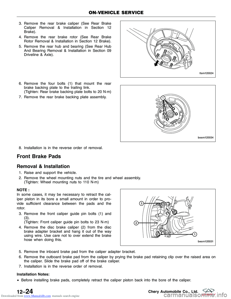
6. Remove the four bolts (1) that mount the rear brake backing plate to the trailing link.
(Tighten: Rear brake backing plate bolts to 20 N·m)
7. Remove the rear brake backing plate assembly.
8. Installation is in the reverse order of removal.
Front Brake Pads
Removal & Installation
1. Raise and support the vehicle.
2. Remove the wheel mounting nuts and the tire and wheel assembly. (Tighten: Wheel mounting nuts to 110 N·m)
NOTE :
In some cases, it may be necessary to retract the cal-
iper piston in its bore a small amount in order to pro-
vide sufficient clearance between the pads and the
rotor. 3. Remove the front caliper guide pin bolts (1) and (3).
(Tighten: Front caliper guide pin bolts to 23 N·m)
4. Remove the disc brake caliper (2) from the disc brake adapter bracket and hang it out of the way
using wire. Use care not to over extend the brake
hose when doing this.
5. Remove the inboard brake pad from the caliper adapter bracket.
6. Remove the outboard brake pad from the caliper by prying the brake pad retaining clip over the raised area on the caliper. Slide the brake pad off of the brake caliper.
7. Installation is in the reverse order of removal.
Installation Notes:
• Before installing brake pads, completely retract the caliper piston back into the bore of the caliper.
ON-VEHICLE SERVICE
LTSM120024
BESM120034
BESM120031
12–24Chery Automobile Co., Ltd.
Page 1420 of 1903

Downloaded from www.Manualslib.com manuals search engine •After installation and before moving the vehicle, pump the brake pedal several times to set the pads to the
brake rotor.
• Check and adjust the brake fluid level in the reservoir as necessary.
• Road test the vehicle and make several stops to wear off any foreign material on the brakes and to seat the
brake pads.
• After installation and before moving the vehicle, pump the brake pedal several times to set the pads to the
brake rotor.
Inspection
Visually inspect brake pads for uneven lining wear. Also inspect for excessive lining deterioration. Check the clear-
ance between the tips of the wear indicators (if equipped) on the pads and the brake rotors. If a visual inspection
does not adequately determine the condition of the lining, a physical check will be necessary. To check the amount
of lining wear, remove the disc brake pads from the vehicle. Measure the brake pad minimum thickness. Brake pads
must be replaced when usable material on a brake pad lining measured at its thinnest point measures one millimeter
or less. Replace both disc brake pads (inboard and outboard) at each caliper. It is also necessary to replace the pads
on the opposite side of the vehicle as well as the pads failing inspection to maintain proper braking characteristics.
If the brake pad assemblies do not require replacement, be sure to reinstall the brake pads in the original position
from which they were removed.
Rear Brake Pads
Removal & Installation
1. Raise and support the vehicle.
2. Remove the wheel mounting nuts and the tire and wheel assembly.
(Tighten: Wheel mounting nuts to 110 N·m)
NOTE :
In some cases, it may be necessary to retract the caliper piston in its bore a small amount in order to provide suf-
ficient clearance between the pads and the rotor. 3. Remove the lower rear caliper guide pin bolt (2). (Tighten: Rear caliper guide pin bolt to 23 N·m)
CAUTION: When moving rear brake caliper
upward, use extreme care not to damage or
overextend the flex hose.
4. Rotate the caliper (1) upward hinging off the upper guide pin bolt. Rotate the caliper upward just
enough to allow brake pad removal.
5. Slide the rear brake pads off of the brake caliper adapter.
ON-VEHICLE SERVICE
LTSM120044
LTSM120018
12
12–25Chery Automobile Co., Ltd.
Page 1421 of 1903
Downloaded from www.Manualslib.com manuals search engine Inspection
Visually inspect brake pads for uneven lining wear. Also inspect for excessive lining deterioration. Check the clear-
ance between the tips of the wear indicators (if equipped) on the pads and the brake rotors. If a visual inspection
does not adequately determine the condition of the lining, a physical check will be necessary. To check the amount
of lining wear, remove the disc brake pads from the vehicle. Measure the brake pad minimum thickness. Brake pads
must be replaced when usable material on a brake pad lining measured at its thinnest point measures one millimeter
or less. Replace both disc brake pads (inboard and outboard) at each caliper. It is also necessary to replace the pads
on the opposite side of the vehicle as well as the pads failing inspection to maintain proper braking characteristics.
If the brake pad assemblies do not require replacement, be sure to reinstall the brake pads in the original position
from which they were removed.
ON-VEHICLE SERVICE
12–26Chery Automobile Co., Ltd.
Page 1422 of 1903
Downloaded from www.Manualslib.com manuals search engine UNIT REPAIR
Front Brake Caliper
Disassemble
Before disassembling the brake caliper, clean and inspect it.
WARNING!
•Under no condition should high pressure air ever be used to remove a piston from a caliper bore. Personal
injury could result from such a practice.
• Do not place face or hands near caliper and piston if using compressed air pressure to remove piston. Do not
use high pressure.
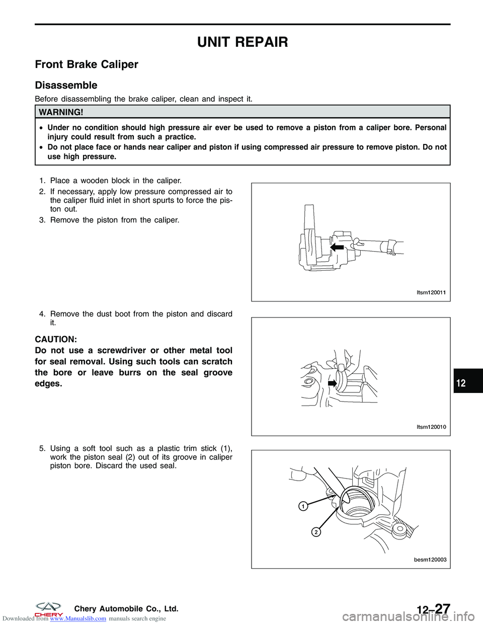
1. Place a wooden block in the caliper.
2. If necessary, apply low pressure compressed air to
the caliper fluid inlet in short spurts to force the pis-
ton out.
3. Remove the piston from the caliper.
4. Remove the dust boot from the piston and discard it.
CAUTION:
Do not use a screwdriver or other metal tool
for seal removal. Using such tools can scratch
the bore or leave burrs on the seal groove
edges.
5. Using a soft tool such as a plastic trim stick (1),work the piston seal (2) out of its groove in caliper
piston bore. Discard the used seal.
LTSM120011
LTSM120010
BESM120003
12
12–27Chery Automobile Co., Ltd.
Page 1423 of 1903
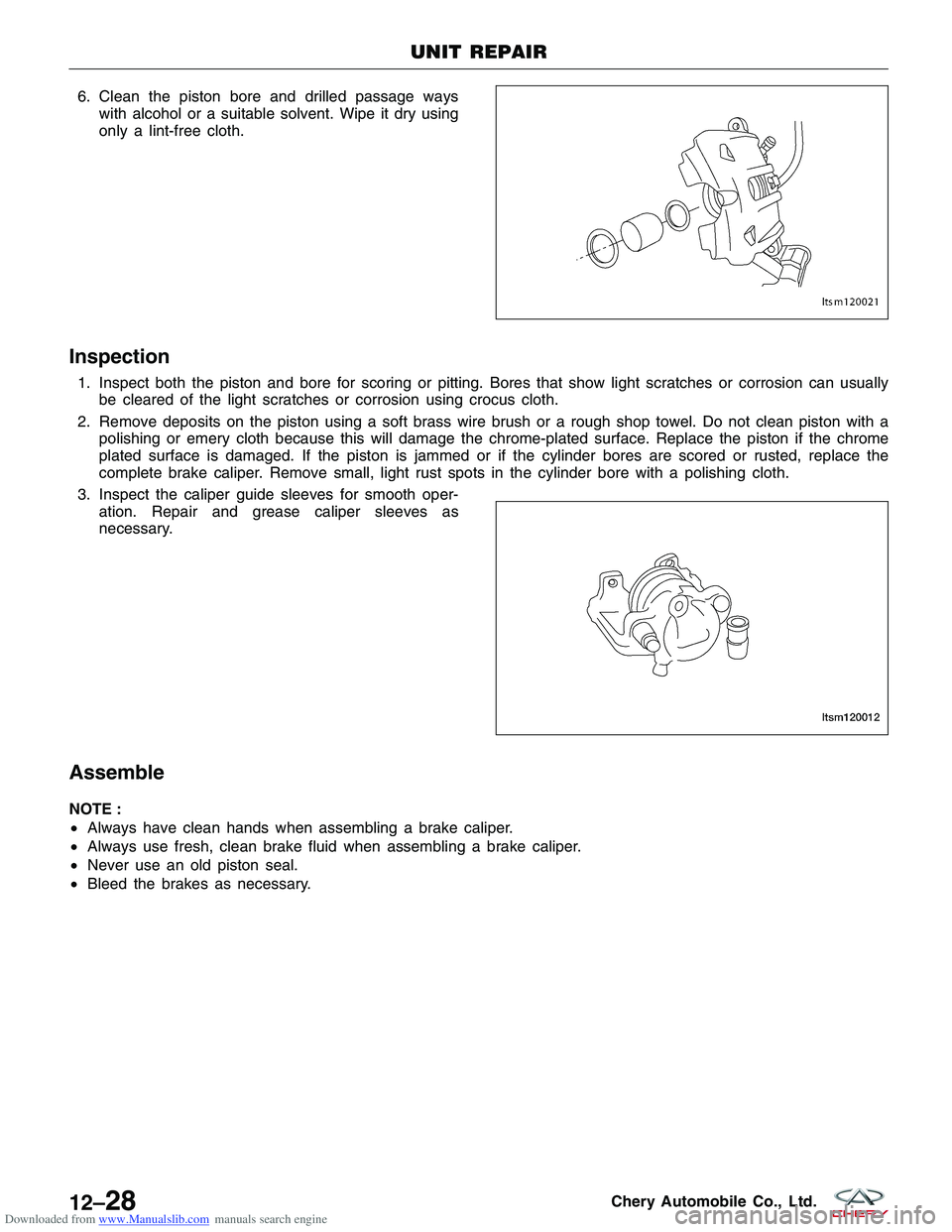
Downloaded from www.Manualslib.com manuals search engine 6. Clean the piston bore and drilled passage wayswith alcohol or a suitable solvent. Wipe it dry using
only a lint-free cloth.
Inspection
1. Inspect both the piston and bore for scoring or pitting. Bores that show light scratches or corrosion can usuallybe cleared of the light scratches or corrosion using crocus cloth.
2. Remove deposits on the piston using a soft brass wire brush or a rough shop towel. Do not clean piston with a polishing or emery cloth because this will damage the chrome-plated surface. Replace the piston if the chrome
plated surface is damaged. If the piston is jammed or if the cylinder bores are scored or rusted, replace the
complete brake caliper. Remove small, light rust spots in the cylinder bore with a polishing cloth.
3. Inspect the caliper guide sleeves for smooth oper- ation. Repair and grease caliper sleeves as
necessary.
Assemble
NOTE :
•Always have clean hands when assembling a brake caliper.
• Always use fresh, clean brake fluid when assembling a brake caliper.
• Never use an old piston seal.
• Bleed the brakes as necessary.
UNIT REPAIR
LTSM120021
LTSM120012
12–28Chery Automobile Co., Ltd.
Page 1424 of 1903
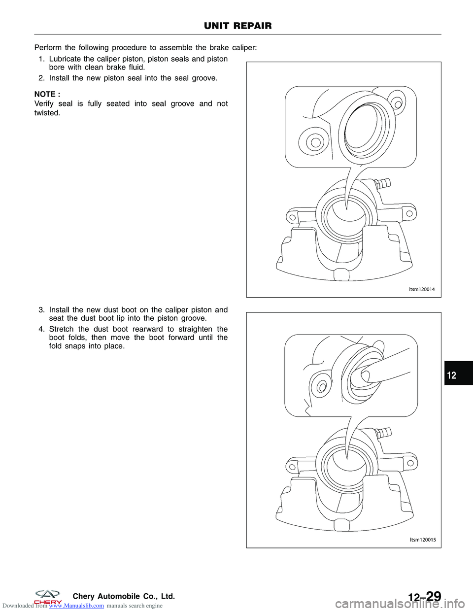
Downloaded from www.Manualslib.com manuals search engine Perform the following procedure to assemble the brake caliper:1. Lubricate the caliper piston, piston seals and piston bore with clean brake fluid.
2. Install the new piston seal into the seal groove.
NOTE :
Verify seal is fully seated into seal groove and not
twisted.
3. Install the new dust boot on the caliper piston and seat the dust boot lip into the piston groove.
4. Stretch the dust boot rearward to straighten the boot folds, then move the boot forward until the
fold snaps into place.
UNIT REPAIR
LTSM120014
LTSM120015
12
12–29Chery Automobile Co., Ltd.