2009 CHERY TIGGO low oil pressure
[x] Cancel search: low oil pressurePage 26 of 1903

Downloaded from www.Manualslib.com manuals search engine HOW TO LOCATE ELECTRICAL SCHEMATICS IN THESERVICE MANUAL
Electrical Schematic Index
The following table shows where to locate a specific electrical schematic for a vehicle component or system. The
electrical schematics are found throughout the service manual and are easily identified by their components or vehi-
cle systems.
NOTE :
Some service manual chapters DO NOT contain electrical schematics, and will be identified as Nonein the Com-
ponent/Vehicle System column.
SERVICE MANUAL CHAPTER COMPONENT / VEHICLE SYSTEM
01 - General Information •None
02 - Engine •None
03 - Electronic Engine Controls •
Engine Control Module (ECM)
• Engine Coolant Temperature Sensor
• Knock Sensor
• Upstream Oxygen Sensor
• Downstream Oxygen Sensor
• Crankshaft Position Sensor
• Camshaft Position Sensor
• Ignition Coil
• Canister Control Valve
• Front Fuse and Relay Box
• A/C Compressor
• Immobilizer Control Module
• Fuel Injectors
• Manifold Absolute Pressure Sensor (1.6L Only)
• Accelerator Pedal Position Sensor
• Vehicle Speed Sensor
• Throttle Pedal Position Sensor
• Power Steering Switch
• Clutch Pedal Switch (if equipped)
• Electronic Throttle Control Actuator
04 - Fuel Delivery •
Fuel Injectors
• Fuel Level Sensor and Fuel Pump
05 - Starting & Charging •
Starter Motor
• Ignition Switch
• Clutch Pedal Switch (if equipped)
• Generator
06 - Cooling System •Cooling Fan
07 - Exhaust •None
01
01–25Chery Automobile Co., Ltd.
Page 29 of 1903

Downloaded from www.Manualslib.com manuals search engine TERMABBREVIATION
Front Left Wheel Speed Sensor FLS
Front Right Wheel Speed Sensor FRS
Rear Left Wheel Speed Sensor RCS
Rear Right Wheel Speed Sensor RRS
Ground GND
Heated Oxygen Sensor O2S
Idle Air Control IAC
Intake Air Temperature IAT
Ignition IGN
Ignition Control IC
Immobilizer Control Module ICM
Injector INJ
Input Shaft Speed Sensor ISS Sensor
Knock Sensor KS
Manifold Absolute Pressure MAP
Mass Air Flow MAF
Malfunction Indicator Lamp MIL
Oil Pressure Switch OPS
Output Shaft Speed Sensor OSS Sensor
Positive Crankcase Ventilation Valve PCV Valve
Power Supply PWR
SRS Airbag Control System SRC
Throttle Position Sensor TPS
Transaxle Control Module TCM
Turbine Speed Sensor TSS
Vehicle Identification Number VIN
Vehicle Speed Sensor VSS
HOW TO LOCATE ELECTRICAL SCHEMATICS IN THE SERVICE MANUAL
01–28Chery Automobile Co., Ltd.
Page 32 of 1903

Downloaded from www.Manualslib.com manuals search engine GENERAL INFORMATION
Description
The 1.6L & 1.8L in-line four cylinder engines have the following features:
•Dual overhead camshafts
• Four valves per cylinder
• Aluminum cylinder head
• Cast iron cylinder block (1.8L Engine)
• Aluminum cylinder block (1.6L Engine)
Operation
The 1.6L & 1.8L engines utilize 4 valve-per-cylinder and a dual overhead camshaft design. The engines use an indi-
vidual coil ignition system. The 1.6L engine uses an aluminum cylinder block, and the 1.8L engine is made of cast
iron. The bearing caps are integrated into the lower cylinder block assembly. An aluminum oil pan bolts to the bottom
of the lower cylinder block. The camshafts are mounted in the cylinder head and act against valve tappets to open
and close the valves. The camshafts are driven off the front of the cylinder head by one timing belt. The belt is driven
by a sprocket that is located on the crankshaft. The piston assembly is an aluminum piston with a cast iron con-
necting rod.
The aluminum cylinder head contains dual overhead camshafts with 4 valve-per-cylinder construction. The valves are
arranged in two in-line banks. The cylinder head incorporates powdered metal valve guides and seats. The cylinder
head is sealed to the block using a multi-layer steel head gasket and retaining bolts.
Specifications
1.6L Engine Specifications
DESCRIPTION SPECIFICATION
Type In-Line OHV, DOHC
Number of Cylinders 4
Compression Ratio 10.5:1
Compression Pressure 10 - 15 bar
Max. Compression Pressure Variation Between
Cylinders 25%
Stroke 77.5 mm
Bore 81 mm
Displacement 1597 cc
Firing Order 1-3-4-2
1.8L Engine Specifications
DESCRIPTIONSPECIFICATION
Type In-Line OHV, DOHC
Number of Cylinders 4
Compression Ratio 10.5:1
Compression Pressure 10 - 15 bar
Max. Compression Pressure Variation Between
Cylinders 25%
Stroke 89.5 mm
Bore 81 mm
Displacement 1845 cc
Firing Order 1-3-4-2
02
02–3Chery Automobile Co., Ltd.
Page 33 of 1903

Downloaded from www.Manualslib.com manuals search engine Mechanical Specifications
DESCRIPTIONITEMSTANDARD LIMIT
Engine Oil Pressure Lower Idle Speed (800 ±
50 RPM) 1.2 - 1.5 bar
-
High Idle Speed (2000 RPM) 3.2 - 3.5 bar
-
High Speed (4000 RPM) 3.7 ± 0.5 bar -
Engine Block Clearance Surface Distortion
-0.15 mm
Inner Diameter 81.000 - 81.010 mm -
Out-Of-Round -< 0.008 mm
Taper -< 0.01 mm
Piston Ring Groove
Clearance First Ring
0.04 - 0.08 mm -
Second Ring 0.0251 - 0.01 mm -
Piston Ring End Gap
Clearance First Ring
0.2 - 0.4 mm 0.8 mm
Second Ring 0.4 - 0.6 mm 1.0 mm
Piston To Piston Pin
Clearance -
0.002 - 0.013 mm -
Piston Diameter -80.946 - 80.964 mm -
Ring Groove Clearance First Ring
0.04 - 0.08 mm -
Second Ring 0.01 - 0.0251 mm -
Connecting Rod Radial
Clearance -
0.016 - 0.051 mm -
Connecting Rod Axial
Clearance -
0.002 - 0.013 mm -
Diameter Of Crankshaft
Main Journals -
53.981 - 54 mm -
Diameter Of Crankshaft
Rod Journals -
47.884 - 47.9 mm -
Out-Of-Round Maximum
Of Crankshaft Main
Journals -
-< 0.008 mm
Axial Clearance Of
Crankshaft -
0.07 - 0.265 mm -
Radial Clearance Of
Crankshaft -
0.0035 - 0.034 mm -
Coaxality Crankshaft Main
Journal -
-< 0.005 mm
Thrust Washer Thickness -2.4 - 2.405 mm -
Oil Clearance Of
Crankshaft Rod and Main
Journals -
0.022 mm 0.058 mm
Cylinder Head Flatness --< 0.04 mm
Intake Valve Deflection --< 0.02 mm
Exhaust Valve Deflection --< 0.04 mm
Spring Height -47.7 mm -
Spring Height At 620
Newtons Of Pressure -
32.0 mm -
GENERAL INFORMATION
02–4Chery Automobile Co., Ltd.
Page 39 of 1903

Downloaded from www.Manualslib.com manuals search engine Flywheel FixtureCH-20043
Engine Hoist
Oil Filter Remover CH-10003
Lubrication System
The engine lubrication system operates as follows:
•Oil is drawn into the oil pump through the oil pump strainer tube in the sump of the oil pan.
• Oil is pumped through the oil filter on the cylinder block.
• Oil enters the main oil gallery where it is distributed to the crankshaft main journals and to the cylinder head.
• From the main journals, the oil is routed through cross-drilled passages in the crankshaft to lubricate the con-
necting rod bearings. Controlled leakage through the crankshaft main bearings and connecting rod bearings is
slung radially outward to cool and lubricate the cylinder walls as well as the entire connecting rod, piston and
piston ring assembly.
• The engine lubrication system is a full-flow filtration, pressure feed type. The oil pump body is mounted to the
engine block. The pump inner rotor is driven by the crankshaft.
Engine Oil Pressure Specifications
Lower Idle Speed (800 ± 50 RPM) 1.2 - 1.5 bar
High Idle Speed (2000 RPM) 3.2 - 3.5 bar
High Speed (4000 RPM) 3.7 ± 0.5 bar
GENERAL INFORMATION
02–10Chery Automobile Co., Ltd.
Page 41 of 1903

Downloaded from www.Manualslib.com manuals search engine Engine Oil Flow Diagram
1 - Oil Pump Strainer
2 - Baffle Plate
3 - Oil Pan
4 - Oil Pump
5 - Turbocharger Inlet Oil Passage (if equipped)
6 - To Cylinder Head
7 - Oil Return Passage
8 - To Front Bearing Cap9 - To Middle Bearing Cap
10 - Oil Dipstick
11 - To Crankcase
12 - Crankcase Pipe
13 - Oil Filter Bracket
14 - Oil Pressure Switch
15 - Oil Cooler
16 - Oil Filter
GENERAL INFORMATION
BESM020088
02–12Chery Automobile Co., Ltd.
Page 43 of 1903
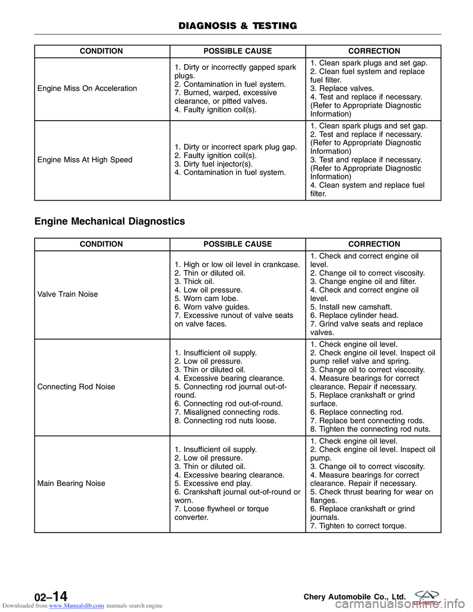
Downloaded from www.Manualslib.com manuals search engine CONDITIONPOSSIBLE CAUSE CORRECTION
Engine Miss On Acceleration 1. Dirty or incorrectly gapped spark
plugs.
2. Contamination in fuel system.
7. Burned, warped, excessive
clearance, or pitted valves.
4. Faulty ignition coil(s).1. Clean spark plugs and set gap.
2. Clean fuel system and replace
fuel filter.
3. Replace valves.
4. Test and replace if necessary.
(Refer to Appropriate Diagnostic
Information)
Engine Miss At High Speed 1. Dirty or incorrect spark plug gap.
2. Faulty ignition coil(s).
3. Dirty fuel injector(s).
4. Contamination in fuel system.1. Clean spark plugs and set gap.
2. Test and replace if necessary.
(Refer to Appropriate Diagnostic
Information)
3. Test and replace if necessary.
(Refer to Appropriate Diagnostic
Information)
4. Clean system and replace fuel
filter.
Engine Mechanical Diagnostics
CONDITION
POSSIBLE CAUSE CORRECTION
Valve Train Noise 1. High or low oil level in crankcase.
2. Thin or diluted oil.
3. Thick oil.
4. Low oil pressure.
5. Worn cam lobe.
6. Worn valve guides.
7. Excessive runout of valve seats
on valve faces.1. Check and correct engine oil
level.
2. Change oil to correct viscosity.
3. Change engine oil and filter.
4. Check and correct engine oil
level.
5. Install new camshaft.
6. Replace cylinder head.
7. Grind valve seats and replace
valves.
Connecting Rod Noise 1. Insufficient oil supply.
2. Low oil pressure.
3. Thin or diluted oil.
4. Excessive bearing clearance.
5. Connecting rod journal out-of-
round.
6. Connecting rod out-of-round.
7. Misaligned connecting rods.
8. Connecting rod nuts loose.1. Check engine oil level.
2. Check engine oil level. Inspect oil
pump relief valve and spring.
3. Change oil to correct viscosity.
4. Measure bearings for correct
clearance. Repair if necessary.
5. Replace crankshaft or grind
surface.
6. Replace connecting rod.
7. Replace bent connecting rods.
8. Tighten the connecting rod nuts.
Main Bearing Noise 1. Insufficient oil supply.
2. Low oil pressure.
3. Thin or diluted oil.
4. Excessive bearing clearance.
5. Excessive end play.
6. Crankshaft journal out-of-round or
worn.
7. Loose flywheel or torque
converter.1. Check engine oil level.
2. Check engine oil level. Inspect oil
pump.
3. Change oil to correct viscosity.
4. Measure bearings for correct
clearance. Repair if necessary.
5. Check thrust bearing for wear on
flanges.
6. Replace crankshaft or grind
journals.
7. Tighten to correct torque.
DIAGNOSIS & TESTING
02–14Chery Automobile Co., Ltd.
Page 44 of 1903
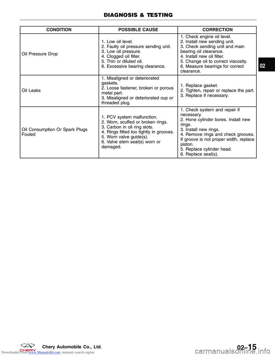
Downloaded from www.Manualslib.com manuals search engine CONDITIONPOSSIBLE CAUSE CORRECTION
Oil Pressure Drop 1. Low oil level.
2. Faulty oil pressure sending unit.
3. Low oil pressure.
4. Clogged oil filter.
5. Thin or diluted oil.
6. Excessive bearing clearance.1. Check engine oil level.
2. Install new sending unit.
3. Check sending unit and main
bearing oil clearance.
4. Install new oil filter.
5. Change oil to correct viscosity.
6. Measure bearings for correct
clearance.
Oil Leaks 1. Misaligned or deteriorated
gaskets.
2. Loose fastener, broken or porous
metal part.
3. Misaligned or deteriorated cup or
threaded plug.1. Replace gasket.
2. Tighten, repair or replace the part.
3. Replace if necessary.
Oil Consumption Or Spark Plugs
Fouled 1. PCV system malfunction.
2. Worn, scuffed or broken rings.
3. Carbon in oil ring slots.
4. Rings fitted too tightly in grooves.
5. Worn valve guide(s).
6. Valve stem seal(s) worn or
damaged.1. Check system and repair if
necessary.
2. Hone cylinder bores. Install new
rings.
3. Install new rings.
4. Remove rings and check grooves.
If groove is not proper width, replace
piston.
5. Replace cylinder head.
6. Replace seal(s).
DIAGNOSIS & TESTING
02
02–15Chery Automobile Co., Ltd.