2009 CHERY TIGGO air suspension
[x] Cancel search: air suspensionPage 1 of 1903

Downloaded from www.Manualslib.com manuals search engine 2009
CHERY
Tiggo
Service Manual
FOREWORD
This manual contains on-vehicle service
and diagnosis procedures for the Chery Tiggo.
A thorough familiarization with this manual
is important for proper repair and
maintenance. It should always be kept in a
handy place for quick and easy reference.
The contents of this manual, including
drawings and specifications, are the latest
available at the time of printing. As
modifications affecting repair or
maintenance occur, relevant information
supplementary to this volume will be made
available at Chery dealers. This manual
should be kept up-to-date.
Chery Automobile Company, Ltd. reserves the
right to alter the specifications and
contents of this manual without obligation
or advance notice.
All rights reserved. No part of this book
may be reproduced or used in any form or
by any means, electronic or mechanical—
including photocopying and recording and the
use of any kind of information storage and
retrieval system—without permission in
writing.
NOTE:
This Tiggo service manual only applies to the fol-
lowing engines and transaxles:
• 1.6L with M/T
• 1.8L with M/T
• 2.0L with A/T
• 2.4L with A/T
Chery Automobile Company, Ltd.Wuhu, Anhui Province, CHINA
CONTENTS
Title Section
GENERAL INFORMATION01
ENGINE02
ELECTRONIC ENGINE CONTROLS03
FUEL DELIVERY04
STARTING & CHARGING05
COOLING06
EXHAUST07
TRANSAXLE & TRANSFER CASE08
DRIVELINE & AXLE09
SUSPENSION10
STEERING11
BRAKES12
HEATING & AIR CONDITIONING13
RESTRAINTS14
BODY & ACCESSORIES15
WIRING16
ALPHABETICAL INDEXAI
© 2009 Chery Automobile Co., Ltd.
PRINTED NOVEMBER, 2009
Page 27 of 1903

Downloaded from www.Manualslib.com manuals search engine SERVICE MANUAL CHAPTERCOMPONENT / VEHICLE SYSTEM
08 - Transaxle & Transfer Case •
Transaxle Control Module (TCM)
• Automatic Transaxle Shifter Selector
• Automatic Transaxle Assembly
• Manual Transaxle Assembly
• Winter Mode Switch
• EPDE Solenoid Valve
• Backup Lamp Switch
• Integrated Torque Management (ITM) Control Module
09 - Driveline & Axle •None
10 - Suspension •None
11 - Steering •Power Steering Switch
12 - Brakes •
Antilock Brake System (ABS) Module
• Wheel Speed Sensors
• Brake Switch
• Parking Brake Switch
• Brake Fluid Level Switch
13 - Heating & Air Conditioning •
Manual Temperature Control System
• Blower Motor
• A/C Compressor
• Refrigerant Pressure Switch
14 - Restraints •
Restraints Control Module
• Seat Belt Buckle Switch
• Front Crash Sensors
• Driver Airbag
• Passenger Airbag
HOW TO LOCATE ELECTRICAL SCHEMATICS IN THE SERVICE MANUAL
01–26Chery Automobile Co., Ltd.
Page 1302 of 1903
Downloaded from www.Manualslib.com manuals search engine SUSPENSION
10
CONTENTSpage
Front Suspension ..................................................................... 10-1
Rear Suspension .................................................................... 10-25
Alignment ........................................................................\
.. 10-38
Wheels and Tires ................................................................... 10-47
FRONT SUSPENSION
GENERAL INFORMATION10-2
Description 10-2
Operation 10-4
Specifications 10-4
Special Tools 10-5
DIAGNOSIS & TESTING10-6
Vehicle Suspension Troubleshooting Chart 10-6
ON-VEHICLE SERVICE10-7
Front Steering Knuckle 10-7
Description 10-7
Operation 10-7
Removal & Installation 10-7
Front Lower Control Arm 10-9
Description 10-9
Operation 10-9
Removal & Installation 10-9
Front Stabilizer Bar Link 10-11
Removal & Installation 10-11Front Stabilizer Bar
10-12
Removal & Installation 10-12
Front Strut Assembly 10-13
Description 10-13
Operation 10-14
Diagnosis & Testing 10-14
Removal & Installation 10-14
Front Coil Spring 10-16
Description 10-16
Operation 10-16
Removal & Installation 10-16
Front Sub-Frame Assembly 10-17
Removal & Installation 10-17
UNIT REPAIR10-21
Front Strut 10-21
Disassemble 10-21
Inspection 10-22
Strut Disposal Procedure 10-22
Assembly 10-23
10
10–1Chery Automobile Co., Ltd.
Page 1307 of 1903
Downloaded from www.Manualslib.com manuals search engine DIAGNOSIS & TESTING
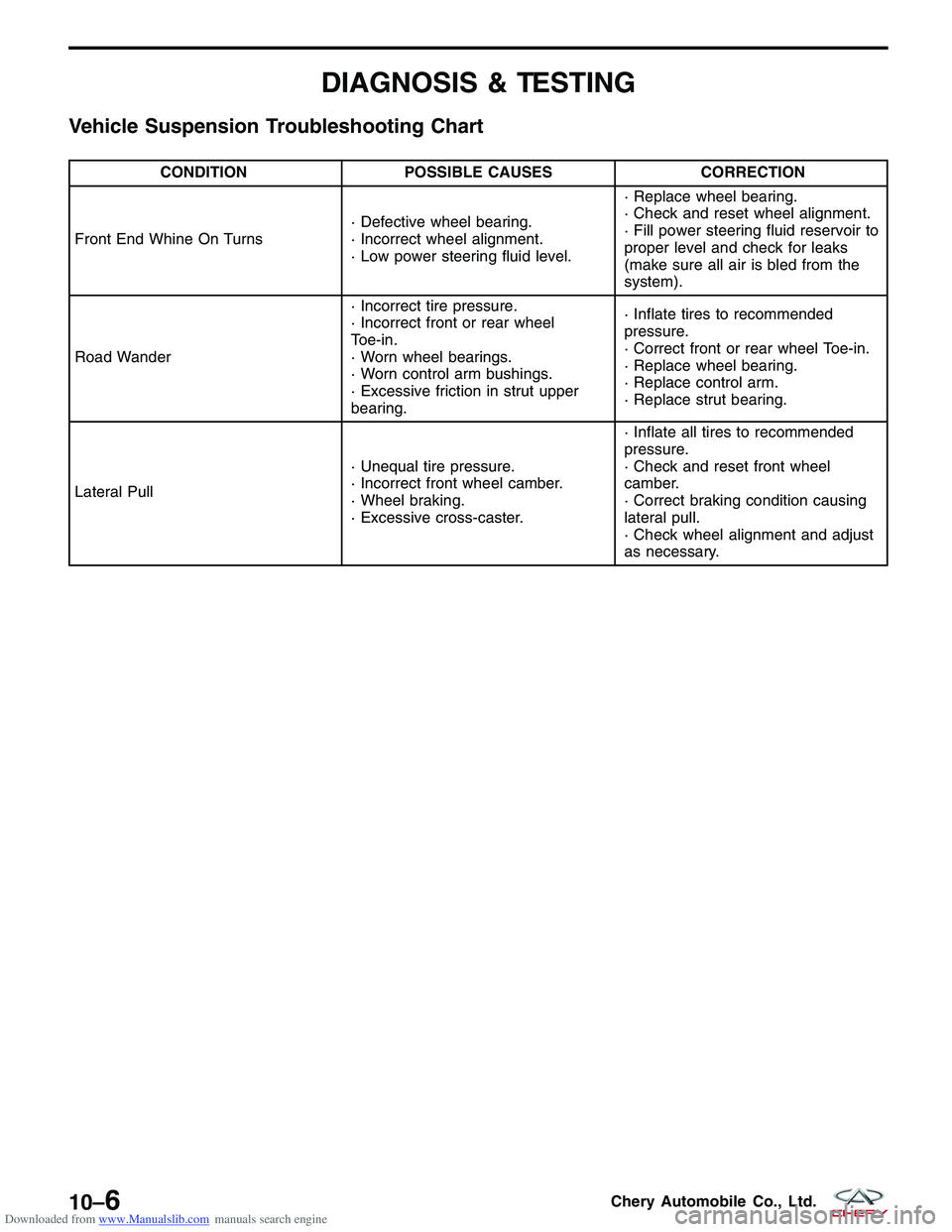
Vehicle Suspension Troubleshooting Chart
CONDITIONPOSSIBLE CAUSES CORRECTION
Front End Whine On Turns · Defective wheel bearing.
· Incorrect wheel alignment.
· Low power steering fluid level.· Replace wheel bearing.
· Check and reset wheel alignment.
· Fill power steering fluid reservoir to
proper level and check for leaks
(make sure all air is bled from the
system).
Road Wander · Incorrect tire pressure.
· Incorrect front or rear wheel
Toe-in.
· Worn wheel bearings.
· Worn control arm bushings.
· Excessive friction in strut upper
bearing.· Inflate tires to recommended
pressure.
· Correct front or rear wheel Toe-in.
· Replace wheel bearing.
· Replace control arm.
· Replace strut bearing.
Lateral Pull · Unequal tire pressure.
· Incorrect front wheel camber.
· Wheel braking.
· Excessive cross-caster.· Inflate all tires to recommended
pressure.
· Check and reset front wheel
camber.
· Correct braking condition causing
lateral pull.
· Check wheel alignment and adjust
as necessary.
10–6Chery Automobile Co., Ltd.
Page 1308 of 1903
Downloaded from www.Manualslib.com manuals search engine ON-VEHICLE SERVICE
Front Steering Knuckle
Description
The steering knuckle is a single casting with legs machined for attachment to the front strut assembly on the top and
steering linkage on the trailing leading end. The steering knuckle also has two machined, drilled legs on the end
casting to support and align the front disc brake caliper adapter.
Operation
The steering knuckle supports the hub and bearing. The front suspension steering knuckle is not a repairable com-
ponent of the front suspension. It must be replaced if damaged in any way. If it is determined that the steering
knuckle is bent when servicing the vehicle, no attempt should be made to straighten the steering knuckle.
Removal & Installation
NOTE :
The following special tools are required to perform the repair procedure:
•CH-10002 - Ball Joint Separator
1. Raise and support the vehicle.
2. Remove the wheel mounting nuts and the wheel assembly. (Tighten: Wheel mounting nuts to 110 N·m)
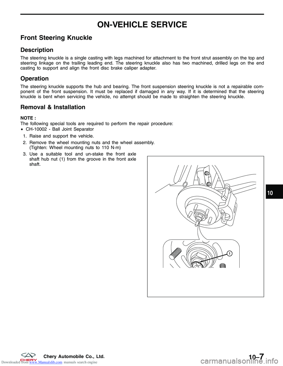
3. Use a suitable tool and un-stake the front axle shaft hub nut (1) from the groove in the front axle
shaft.
??????
10
10–7Chery Automobile Co., Ltd.
Page 1310 of 1903
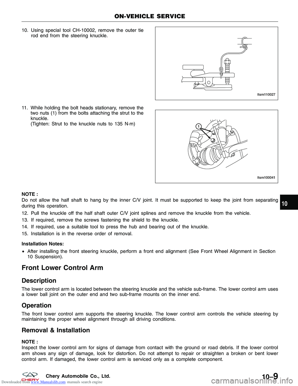
Downloaded from www.Manualslib.com manuals search engine 10. Using special tool CH-10002, remove the outer tierod end from the steering knuckle.
11. While holding the bolt heads stationary, remove the two nuts (1) from the bolts attaching the strut to the
knuckle.
(Tighten: Strut to the knuckle nuts to 135 N·m)
NOTE :
Do not allow the half shaft to hang by the inner C/V joint. It must be supported to keep the joint from separating
during this operation.
12. Pull the knuckle off the half shaft outer C/V joint splines and remove the knuckle from the vehicle.
13. If required, remove the screws fastening the shield to the knuckle.
14. If required, use a suitable tool to press the hub and bearing out of the knuckle.
15. Installation is in the reverse order of removal.
Installation Notes:
• After installing the front steering knuckle, perform a front end alignment (See Front Wheel Alignment in Section
10 Suspension).
Front Lower Control Arm
Description
The lower control arm is located between the steering knuckle and the vehicle sub-frame. The lower control arm uses
a lower ball joint on the outer end and two sub-frame mounts on the inner end.
Operation
The front lower control arm supports the steering knuckle. The lower control arm controls the vehicle steering by
maintaining the proper wheel alignment through all driving conditions.
Removal & Installation
NOTE :
Inspect the lower control arm for signs of damage from contact with the ground or road debris. If the lower control
arm shows any sign of damage, look for distortion. Do not attempt to repair or straighten a broken or bent lower
control arm. If damaged, the lower control arm is serviced only as a complete component.
ON-VEHICLE SERVICE
LTSM110027
LTSM100041
10
10–9Chery Automobile Co., Ltd.
Page 1322 of 1903
Downloaded from www.Manualslib.com manuals search engine UNIT REPAIR
Front Strut
Disassemble
NOTE :
The strut assembly must be removed from the vehicle for it to be disassembled and assembled. For the disassembly
and assembly of the strut assembly, use a strut spring compressor, or the equivalent, to compress the coil spring.
Follow the manufacturer’s instructions closely.1. Remove the front strut assembly (See Front Strut Removal & Installation in Section 10 Suspension).
2. If both struts are being serviced at the same time, mark both the coil springs and strut assemblies according to which side of the vehicle the strut is being removed from.
WARNING!
Do not remove the strut rod nut before the coil spring is properly compressed. The coil spring is held under
pressure. The coil spring must be compressed, removing spring tension from the upper mount and bearing,
before the strut rod nut is removed.
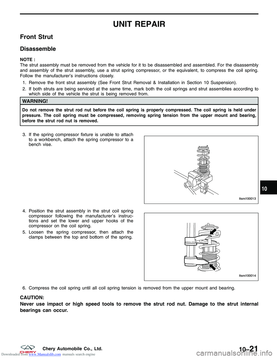
3. If the spring compressor fixture is unable to attachto a workbench, attach the spring compressor to a
bench vise.
4. Position the strut assembly in the strut coil spring compressor following the manufacturer’s instruc-
tions and set the lower and upper hooks of the
compressor on the coil spring.
5. Loosen the spring compressor, then attach the clamps between the top and bottom of the spring.
6. Compress the coil spring until all coil spring tension is removed from the upper mount and bearing.
CAUTION:
Never use impact or high speed tools to remove the strut rod nut. Damage to the strut internal
bearings can occur.
LTSM100013
LTSM100014
10
10–21Chery Automobile Co., Ltd.
Page 1328 of 1903
Downloaded from www.Manualslib.com manuals search engine WARNING!
Only frame contact or wheel lift hoisting equipment can be used on this vehicle. It cannot be hoisted using
equipment designed to lift a vehicle by the rear axle. If this type of hoisting equipment is used, damage to rear
suspension components will occur.
CAUTION:
If a rear suspension component becomes bent, damaged or fails, no attempt should be made to
straighten or repair it. Always replace it with a new component.
Operation
The rear suspension utilizes an independent multi-link arm design. This suspension system allows the wheels to
react to road imperfections independent of each other. This independent action offers improved isolation from the
effects of jounce and rebound.
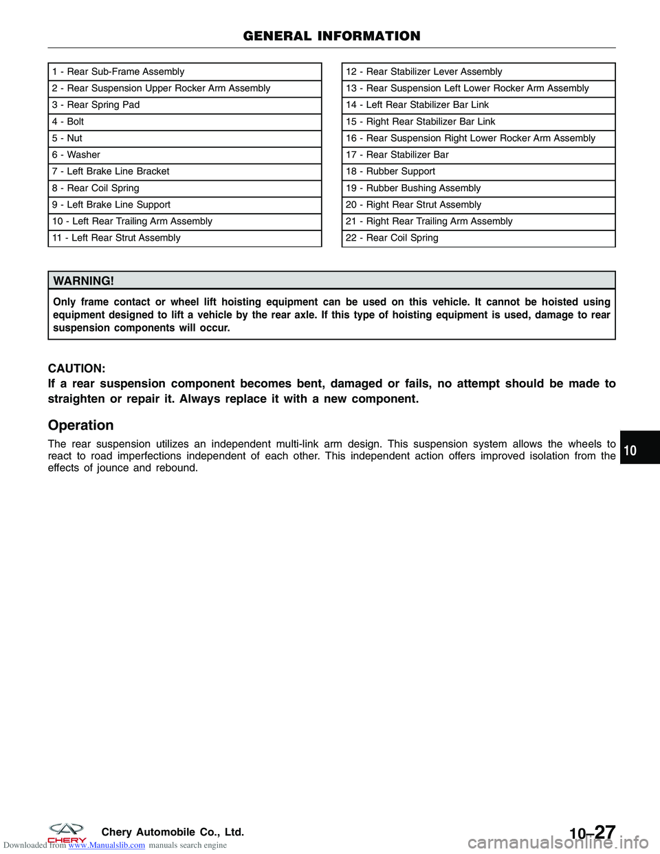
1 - Rear Sub-Frame Assembly
2 - Rear Suspension Upper Rocker Arm Assembly
3 - Rear Spring Pad
4 - Bolt
5 - Nut
6 - Washer
7 - Left Brake Line Bracket
8 - Rear Coil Spring
9 - Left Brake Line Support
10 - Left Rear Trailing Arm Assembly
11 - Left Rear Strut Assembly12 - Rear Stabilizer Lever Assembly
13 - Rear Suspension Left Lower Rocker Arm Assembly
14 - Left Rear Stabilizer Bar Link
15 - Right Rear Stabilizer Bar Link
16 - Rear Suspension Right Lower Rocker Arm Assembly
17 - Rear Stabilizer Bar
18 - Rubber Support
19 - Rubber Bushing Assembly
20 - Right Rear Strut Assembly
21 - Right Rear Trailing Arm Assembly
22 - Rear Coil Spring
GENERAL INFORMATION
LTSM100035
10
10–27Chery Automobile Co., Ltd.