Page 1666 of 1903
Downloaded from www.Manualslib.com manuals search engine 4.CHECK FUEL LEVEL SENSOR CIRCUIT FOR OPEN OR SHORT
• Turn ignition switch off.
• Disconnect the IC connector.
• Check harness for a short to ground.
FUEL LEVEL SENSOR
TERMINAL GROUND
1
Ground
• Check for continuity between the following terminals:
FUEL LEVEL
SENSOR
TERMINAL IC TERMINAL CONTINUITY
12
1Yes
• Continuity should exist.
• Check the harness for a short to power.
Is the check result normal?
Ye s>>Go to the next step.
No
>>Repair or replace the fuel level sensor supply circuit as necessary.
5.CHECK FUEL LEVEL SENSOR GROUND CIRCUIT
• Using a 12 V test light connected to battery (+), probe fuel level sensor ground circuit.
Does the test light illuminate brightly?
Ye s>>Go to the next step.
No
>>Repair or replace the fuel level sensor ground circuit for an open.
DIAGNOSIS & TESTING
15–82Chery Automobile Co., Ltd.
Page 1669 of 1903
Downloaded from www.Manualslib.com manuals search engine INTERIOR LAMPS
Description
The interior lamps consist of the following:
•Key Hole Lamp
• Front Room Lamp
• Middle/Rear Courtesy/Dome Lamp
• Front Step Lamp
• Backlight Adjusting Switch
• Instrument Cluster
• Headlamp Aiming Switch
• Heated Seat Switch (LH)
• Heated Seat Switch (RH)
• Air Control Panel
• Front Fog Lamp Switch
• Rear Fog Lamp Switch
• Console Power Socket (Illumination)
• Door Mirror Remote Control Switch
• Main Power Window And Door Lock/Unlock Switch
• Front Power Window Switch (RH)
• Rear Power Window Switch (LH)
• Rear Power Window Switch (RH)
• Audio
Operation
The key hole lamp and front/middle/rear courtesy lamps are controlled by the BCM. Front step lamps are controlled
by the door lock switch. When the door is open, the front step lamp will light up automatically. Other lamps are
controlled by the lighting and turn signal switch.
15
15–85Chery Automobile Co., Ltd.
Page 1677 of 1903
Downloaded from www.Manualslib.com manuals search engine POWER OUTLET
Description
There are two 12 V electrical outlets. One is under the center console which is for the cigarette lighter. The other is
located on the left lower C-pillar trim panel.
CAUTION:
This power outlet is designed for 12 V (120W) only. Do not use any type of accessory above this
rating.
Operation
The power outlets are powered at all times.
15
15–93Chery Automobile Co., Ltd.
Page 1688 of 1903

Downloaded from www.Manualslib.com manuals search engine SEATS
General Information
Description
The seat movement is controlled by an adjustment bar. The seat can be adjusted to six different seating positions.
The vehicle may be equipped with heated seats. Heated seats provide comfort and warmth in cold weather. The
heaters provide the same heat level for both the seat cushion and back. The driver seat and front passenger seat are
heated.
Operation
The manual seat adjustment bar is at the front of the seat, near the floor. Pull the bar upward and slide the seat
forward or rearward. Release the bar once the seat is in the desired position. To confirm the seat is locked into place,
attempt to move the seat forward and rearward after adjusting the seat. The heated seat controls for each seat are
located near the bottom center of the instrument panel. After turning the ignition ON, the seat heater can be activated
to High or Low heat settings. When the switch is in the middle position, the seat heater is OFF. Each switch is
equipped with LED lights to indicate the level of heat at which each seat is set.
15–104Chery Automobile Co., Ltd.
Page 1706 of 1903

Downloaded from www.Manualslib.com manuals search engine On Board Diagnostic Logic
•Self-diagnosis detection logic.
DTC NO. DTC DEFINITION DTC DETECTION
CONDITION DTC SET
CONDITION POSSIBLE CAUSE
B3042 W-line short circuit
to ground
Ignition switch: ON The Immobilizer
control module
detects a short
ground condition on
the W-Line for at
least 3 seconds.
•
Harness or
connectors
• Immobilizer control
module
• ECM
B3043 W-Line short circuit
to battery The Immobilizer
control module
detects a short
battery condition on
the W-Line for at
least 3 seconds.•
Harness or
connectors
• Immobilizer control
module
• ECM
DTC Confirmation Procedure:
Before performing the following procedure, confirm that battery voltage is more than 12 V.
• Turn ignition switch off.
• Connect the X-431 scan tool to the Data Link Connector (DLC) - use the most current software available.
• Turn ignition switch on, with the scan tool, view and erase stored DTCs in the Immobilizer control module.
• Try to start the engine.
• Turn ignition switch off, and wait a few seconds, then turn the ignition switch on.
• With the scan tool, view active DTCs in the Immobilizer control module.
• If the DTC is detected, the condition is current. Go to Diagnostic Procedure - Step 1.
• If the DTC is not detected, the DTC condition is intermittent (See Diagnostic Help and Intermittent DTC Trou-
bleshooting in Section 15 Body & Accessories for more information).
NOTE :
While performing electrical diagnosis & testing, always refer to the electrical schematics for specific circuit
and component information.
Diagnostic Procedure
1.CHECK GROUND CONNECTION
• Turn ignition switch off.
• Loosen and retighten ground screws on the body (See Ground Inspection in Section 15 Body & Accessories).
• Inspect ground connection C-204 mounting position (See Vehicle Wiring Harness Layout - Main Harness in
Section 16 Wiring).
Is the ground connection OK?
Ye s>>Go to the next step.
No
>>Repair or replace ground connection.
2.CHECK IMMOBILIZER CONTROL MODULE DTC
• With the scan tool, view DTCs in the Immobilizer control module. Refer to DTC confirmation procedure.
Is the warning light flashing and DTC B3042 or B3043 present?
Ye s>>Go to the next step.
No
>>The conditions that caused this code to set are not present at this time (See Diagnostic Help in Sec-
tion 15 Body & Accessories).
DIAGNOSIS & TESTING
15–122Chery Automobile Co., Ltd.
Page 1720 of 1903
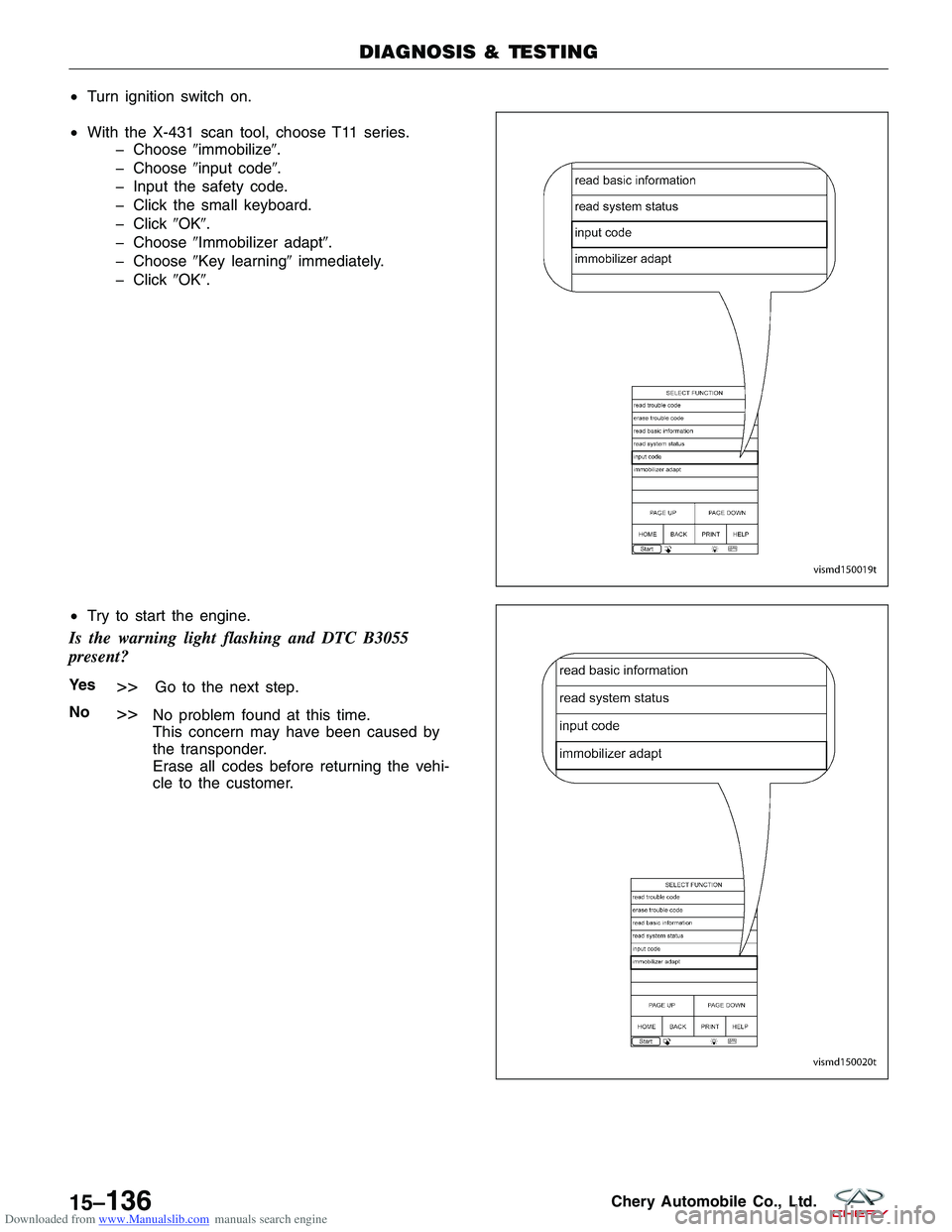
Downloaded from www.Manualslib.com manuals search engine •Turn ignition switch on.
• With the X-431 scan tool, choose T11 series.
� Choose �immobilize�.
� Choose �input code�.
� Input the safety code.
� Click the small keyboard.
� Click �OK�.
� Choose �Immobilizer adapt�.
� Choose �Key learning� immediately.
� Click �OK�.
• Try to start the engine.
Is the warning light flashing and DTC B3055
present?
Ye s>>Go to the next step.
No
>>No problem found at this time.
This concern may have been caused by
the transponder.
Erase all codes before returning the vehi-
cle to the customer.
DIAGNOSIS & TESTING
VISMD150019T
VISMD150020T
15–136Chery Automobile Co., Ltd.
Page 1721 of 1903
Downloaded from www.Manualslib.com manuals search engine 7.REPLACE AND PROGRAM IMMOBILIZER CONTROL MODULE
• Using the wiring schematic as a guide, inspect the related wiring and connectors of the Immobilizer control
module.
• Verify that there is good terminal contact in the related connectors.
• Try to start the engine.
• With the X-431 scan tool, view active DTCs in the Immobilizer control module.
Is the warning light flashing and DTC B3055 or B3056 still present?
Ye s>>Replace and match the Immobilizer control module (This concern may have been caused by Immobi-
lizer control module internal fault). Refer to DTC B3077 Diagnostic Procedure.
No
>>No problem found at this time.
This concern may have been caused by a loose or corroded terminal or connector.
Erase all codes before returning the vehicle to the customer.
DIAGNOSIS & TESTING
15
15–137Chery Automobile Co., Ltd.
Page 1739 of 1903
Downloaded from www.Manualslib.com manuals search engine Cross section A1-A1, requirements for clearance and
levelness.
Cross section A2-A2, requirements for clearance and
levelness.
Cross section A3-A3, requirements for clearance and
levelness.
Cross section A4-A4, requirements for clearance and
levelness.
Cross section A5-A5, requirements for clearance and
levelness.
1 - Hood2 - Fender
1 - Fillet2 - Turning Light
BODY DIMENSIONS
LTSM150006
LTSM150007
LTSM150008
15
15–155Chery Automobile Co., Ltd.