Page 1746 of 1903
Downloaded from www.Manualslib.com manuals search engine Cross section C3-C3, requirements for clearance and
levelness.
Cross section C4-C4, requirements for clearance and
levelness.
Cross section C5-C5, requirements for clearance and
levelness.
1 - Side Wall2 - Rear Bumper
1 - Side Wall2 - Rear Headlight
1 - Fuel Tank Cover 2 - Side Wall
BODY DIMENSIONS
LTSM150023
LTSM150024
LTSM150025
15–162Chery Automobile Co., Ltd.
Page 1749 of 1903
Downloaded from www.Manualslib.com manuals search engine Cross section D4-D4, requirements for clearance and
levelness.
Cross section D5-D5, requirements for clearance and
levelness.
1 - Rear Back Door2 - Rear Headlight
1 - Right Section Of Rear
Bumper 2 - Middle Section Of Rear
Bumper
BODY DIMENSIONS
LTSM150030
LTSM150031
15
15–165Chery Automobile Co., Ltd.
Page 1750 of 1903
Downloaded from www.Manualslib.com manuals search engine BUMPERS
Front Bumper
Removal & Installation
1. Remove the left and right headlamp (See Headlamp Removal & Installation in Section 15 Body & Accessories).
2. Remove the three front bumper mounting bolts (1).
3. Remove the front bumper side mounting bolts and the connecting bolts (3) from the front wheel house.
4. Raise the vehicle and remove the mounting bolts (2) under the front bumper.
5. Disconnect the front fog light electrical connectors and remove the front bumper.
6. Installation is in the reverse order of removal.
LTSM150074
15–166Chery Automobile Co., Ltd.
Page 1762 of 1903

Downloaded from www.Manualslib.com manuals search engine EXTERIOR LAMPS
Description
The exterior lamps consist of the following:
•Headlamps
• Rear Combination Lamps
• Side Repeater Lamps
• Fog Lamps
• Stop Lamps
• Backup Lamps
Operation
•Front Combination Lamp: With the light switch in the 2nd position, the Body Control Module (BCM) receives
input requesting head lamp operation. The BCM then supplies power to the head lamps.
• Turn Signal Lamp: When the turn signal switch is in LH or RH position with the ignition switch in the ON posi-
tion, the FBCM detects the RH or LH turn signal request. The BCM supplies power to the respective turn signal
lamp.
• Hazard Lamp: When the hazard switch is in the ON position, the BCM detects the hazard switch signal. The
BCM outputs the flasher signal (right and left). The BCM then activates the hazard indicator and audible
buzzer.
• Fog Lamp: When the front/rear fog lamp switch is in the ON position and also the light switch is in the 1st or
2nd position. The BCM receives input requesting fog lamp operation. The BCM then supplies power to the fog
lamps.
• Stop Lamp: When the brake pedal is applied, the stop lamp switch sends the signal to the RBCM. The RBCM
then supplies power to the stop lamps.
• Backup Lamp: When the BCM receives the signal from the backup lamp switch, then the BCM supplies power
to the backup lamp.
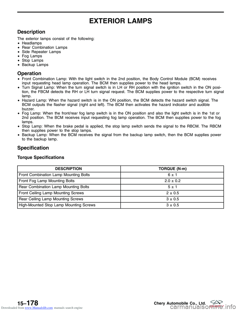
Specification
Torque Specifications
DESCRIPTION TORQUE (N·m)
Front Combination Lamp Mounting Bolts 6 ± 1
Front Fog Lamp Mounting Bolts 2.0 ± 0.2
Rear Combination Lamp Mounting Bolts 5 ± 1
Front Ceiling Lamp Mounting Screws 2 ± 0.5
Rear Ceiling Lamp Mounting Screws 3 ± 0.5
High-Mounted Stop Lamp Mounting Screws 3 ± 0.5
15–178Chery Automobile Co., Ltd.
Page 1774 of 1903

Downloaded from www.Manualslib.com manuals search engine Headlamp Adjustment Procedure
NOTE :
Follow all local laws and regulations and verify the following items before adjustment:1. Check the following before starting the headlamp adjustment procedure: •All tires are filled to the proper tire pressure.
• The vehicle is unloaded (except for spare tire and tools, and include driver’s weight for sedan).
• The vehicle should be parked on a level surface.
• The headlights are clean.
• The headlights are working properly.
2. Park the vehicle on a level surface approximately 10 meters from the vertical wall or screen directly in front of it. NOTE: The vertical wall or screen must be a minimum of 2.4 meters wide.
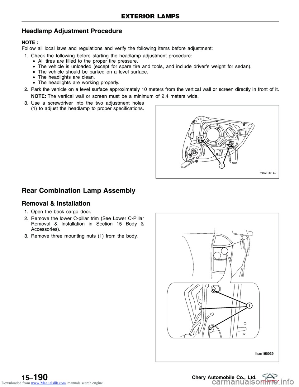
3. Use a screwdriver into the two adjustment holes (1) to adjust the headlamp to proper specifications.
Rear Combination Lamp Assembly
Removal & Installation
1. Open the back cargo door.
2. Remove the lower C-pillar trim (See Lower C-PillarRemoval & Installation in Section 15 Body &
Accessories).
3. Remove three mounting nuts (1) from the body.
EXTERIOR LAMPS
LTSM150149
LTSM150039
15–190Chery Automobile Co., Ltd.
Page 1805 of 1903

Downloaded from www.Manualslib.com manuals search engine 11. Applying the bonding agent:•Cut off the pot tip and fill the bonding agent
into the pot.
• Place the pot into the sealant gun.
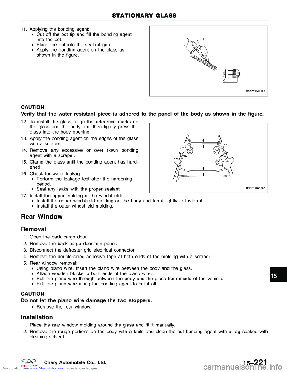
• Apply the bonding agent on the glass as
shown in the figure.
CAUTION:
Verify that the water resistant piece is adhered to the panel of the body as shown in the figure.
12. To install the glass, align the reference marks on
the glass and the body and then lightly press the
glass into the body opening.
13. Apply the bonding agent on the edges of the glass with a scraper.
14. Remove any excessive or over flown bonding agent with a scraper.
15. Clamp the glass until the bonding agent has hard- ened.
16. Check for water leakage: •Perform the leakage test after the hardening
period.
• Seal any leaks with the proper sealant.
17. Install the upper molding of the windshield: •Install the upper windshield molding on the body and tap it lightly to fasten it.
• Install the outer windshield molding.
Rear Window
Removal
1. Open the back cargo door.
2. Remove the back cargo door trim panel.
3. Disconnect the defroster grid electrical connector.
4. Remove the double-sided adhesive tape at both ends of the molding with a scraper.
5. Rear window removal:
•Using piano wire, insert the piano wire between the body and the glass.
• Attach wooden blocks to both ends of the piano wire.
• Pull the piano wire through between the body and the glass from inside of the vehicle.
• Pull the piano wire along the bonding agent to cut it off.
CAUTION:
Do not let the piano wire damage the two stoppers.
•Remove the rear window.
Installation
1. Place the rear window molding around the glass and fit it manually.
2. Remove the rough portions on the body with a knife and clean the cut bonding agent with a rag soaked with
cleaning solvent.
STATIONARY GLASS
BESM150017
BESM150018
15
15–221Chery Automobile Co., Ltd.
Page 1807 of 1903
Downloaded from www.Manualslib.com manuals search engine 11. To install the glass, align the reference marks onthe glass and the body and then lightly press the
glass into the body opening.
12. Apply the bonding agent on the edges of the glass with a scraper.
13. Remove any excessive or over flown bonding agent with a scraper.
14. Clamp the glass until the bonding agent has hard- ened.
15. Check for water leakage: •Perform the leakage test after the hardening
period.
• Seal any leaks with the proper sealant.
16. Install the rear window molding: •Install the rear window outer lower molding on the body and tap it lightly to fasten it.
• Connect the leads of the rear window defroster.
STATIONARY GLASS
BESM150018
15
15–223Chery Automobile Co., Ltd.
Page 1813 of 1903

Downloaded from www.Manualslib.com manuals search engine ON-VEHICLE SERVICE
Sunroof Glass
Removal & Installation
1. Operate the sunroof switch to lift the sunroof to the full tilt position.
2. Push the inner trim strip (side cover inner LH/RH) rearwards to remove.
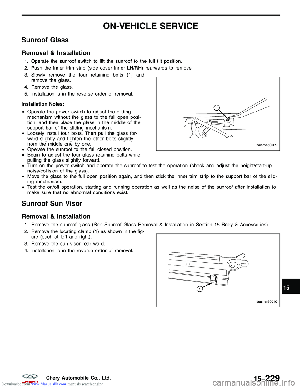
3. Slowly remove the four retaining bolts (1) andremove the glass.
4. Remove the glass.
5. Installation is in the reverse order of removal.
Installation Notes:
• Operate the power switch to adjust the sliding
mechanism without the glass to the full open posi-
tion, and then place the glass in the middle of the
support bar of the sliding mechanism.
• Loosely install four bolts. Then pull the glass for-
ward slightly and tighten the other bolts slightly
from the middle one by one.
• Operate the sunroof to the full closed position.
• Begin to adjust the four glass retaining bolts while
pulling the glass slightly forward.
• Turn on the power switch and operate the sunroof to test the operation (check and adjust the height/start-up
noise/collision of the glass).
• Move the glass to the full open position again, and then stick the inner trim strip to the support bar of the slid-
ing mechanism.
• Test the on/off operation, starting and running operation as well as the noise of the sunroof after installation to
make sure that no abnormal conditions exist.
Sunroof Sun Visor
Removal & Installation
1. Remove the sunroof glass (See Sunroof Glass Removal & Installation in Section 15 Body & Accessories).
2. Remove the locating clamp (1) as shown in the fig-
ure (each at left and right).
3. Remove the sun visor rear ward.
4. Installation is in the reverse order of removal.
BESM150009
BESM150010
15
15–229Chery Automobile Co., Ltd.