Page 1814 of 1903

Downloaded from www.Manualslib.com manuals search engine Sunroof Motor
Removal & Installation
1. Operate the sunroof to the full closed position before disassembling.
2. Remove the roof interior trim/ceiling light.
3. Disconnect the sunroof motor electrical connector and the wiring harness between the sunroof motor and thesunroof control module, and then cut off the band retaining the motor electrical harness.
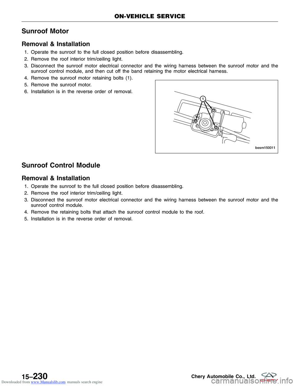
4. Remove the sunroof motor retaining bolts (1).
5. Remove the sunroof motor.
6. Installation is in the reverse order of removal.
Sunroof Control Module
Removal & Installation
1. Operate the sunroof to the full closed position before disassembling.
2. Remove the roof interior trim/ceiling light.
3. Disconnect the sunroof motor electrical connector and the wiring harness between the sunroof motor and the sunroof control module.
4. Remove the retaining bolts that attach the sunroof control module to the roof.
5. Installation is in the reverse order of removal.
ON-VEHICLE SERVICE
BESM150011
15–230Chery Automobile Co., Ltd.
Page 1830 of 1903

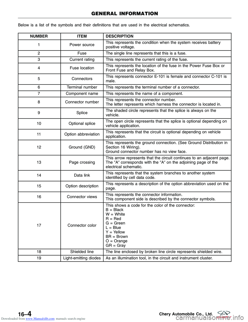
Downloaded from www.Manualslib.com manuals search engine Below is a list of the symbols and their definitions that are used in the electrical schematics.
NUMBERITEM DESCRIPTION
1 Power source This represents the condition when the system receives battery
positive voltage.
2 Fuse The single line represents that this is a fuse.
3 Current rating This represents the current rating of the fuse.
4 Fuse location This represents the location of the fuse in the Power Fuse Box or
Front Fuse and Relay Box.
5 Connectors This represents connector E-101 is female and connector C-101 is
male.
6 Terminal number This represents the terminal number of a connector.
7 Component name This represents the name of a component.
8 Connector number This represents the connector number.
The letter represents which harness the connector is located in.
9 Splice The shaded circle represents that the splice is always on the
vehicle.
10 Optional splice The open circle represents that the splice is optional depending on
vehicle application.
11 Option abbreviation This represents that the circuit is optional depending on vehicle
application.
12 Ground (GND) This represents the ground connection. (See Ground Distribution in
Section 16 Wiring).
Ground connector number has no view face.
13 Page crossing This arrow represents that the circuit continues to an adjacent page.
The
�A�corresponds with the �A�on the adjoining page of the
electrical schematic.
14 Data linkThis represents that the system branches to another system
identified by cell data code.
15 Option description This represents a description of the option abbreviation used on the
page.
16 Connector views This represents the connector information.
This component side is described by the connector symbols.
17 Connector color This shows a code for the color of the connector:
B = Black
W = White
R = Red
G = Green
L = Blue
Y = Yellow
BR = Brown
O = Orange
GR = Gray
18 Shielded line The line enclosed by broken line circle represents shielded wire.
19 Light-emitting diodes As an illumination tool, in the circuit and instrument cluster.
GENERAL INFORMATION
16–4Chery Automobile Co., Ltd.
Page 1831 of 1903

Downloaded from www.Manualslib.com manuals search engine ELECTRICAL TROUBLESHOOTING
Troubleshooting Wiring Problems
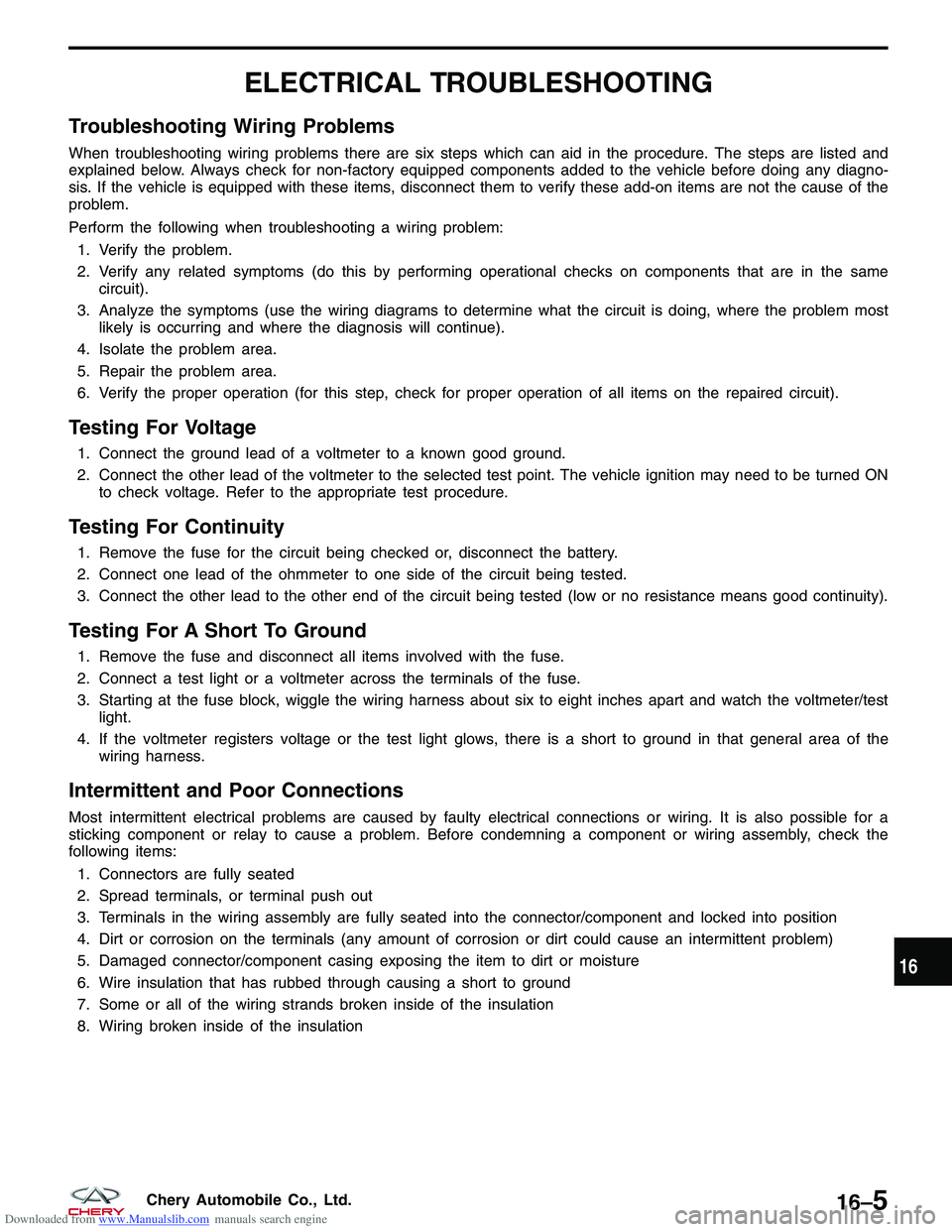
When troubleshooting wiring problems there are six steps which can aid in the procedure. The steps are listed and
explained below. Always check for non-factory equipped components added to the vehicle before doing any diagno-
sis. If the vehicle is equipped with these items, disconnect them to verify these add-on items are not the cause of the
problem.
Perform the following when troubleshooting a wiring problem:1. Verify the problem.
2. Verify any related symptoms (do this by performing operational checks on components that are in the same circuit).
3. Analyze the symptoms (use the wiring diagrams to determine what the circuit is doing, where the problem most likely is occurring and where the diagnosis will continue).
4. Isolate the problem area.
5. Repair the problem area.
6. Verify the proper operation (for this step, check for proper operation of all items on the repaired circuit).
Testing For Voltage
1. Connect the ground lead of a voltmeter to a known good ground.
2. Connect the other lead of the voltmeter to the selected test point. The vehicle ignition may need to be turned ON to check voltage. Refer to the appropriate test procedure.
Testing For Continuity
1. Remove the fuse for the circuit being checked or, disconnect the battery.
2. Connect one lead of the ohmmeter to one side of the circuit being tested.
3. Connect the other lead to the other end of the circuit being tested (low or no resistance means good continuity).
Testing For A Short To Ground
1. Remove the fuse and disconnect all items involved with the fuse.
2. Connect a test light or a voltmeter across the terminals of the fuse.
3. Starting at the fuse block, wiggle the wiring harness about six to eight inches apart and watch the voltmeter/testlight.
4. If the voltmeter registers voltage or the test light glows, there is a short to ground in that general area of the wiring harness.
Intermittent and Poor Connections
Most intermittent electrical problems are caused by faulty electrical connections or wiring. It is also possible for a
sticking component or relay to cause a problem. Before condemning a component or wiring assembly, check the
following items:
1. Connectors are fully seated
2. Spread terminals, or terminal push out
3. Terminals in the wiring assembly are fully seated into the connector/component and locked into position
4. Dirt or corrosion on the terminals (any amount of corrosion or dirt could cause an intermittent problem)
5. Damaged connector/component casing exposing the item to dirt or moisture
6. Wire insulation that has rubbed through causing a short to ground
7. Some or all of the wiring strands broken inside of the insulation
8. Wiring broken inside of the insulation
16
16–5Chery Automobile Co., Ltd.
Page 1837 of 1903
Downloaded from www.Manualslib.com manuals search engine Locking Connector
•When locking connectors, listen for a click indicat-
ing they are securely locked.
Connector Terminals
•Pull lightly on individual wires to check that they
are secured in the terminal.
Connector/Terminal Replacement
•Use the appropriate tools to remove a terminal as
shown. While installing a terminal, be sure to insert
it until it locks securely.
• Insert a thin piece of metal from the terminal side
of the connector and with the terminal locking tab
pressed down, pull the terminal out from the
connector.
ELECTRICAL COMPONENTS
BESM010020
BESM010023
BESM010029
16
16–11Chery Automobile Co., Ltd.
Page 1885 of 1903

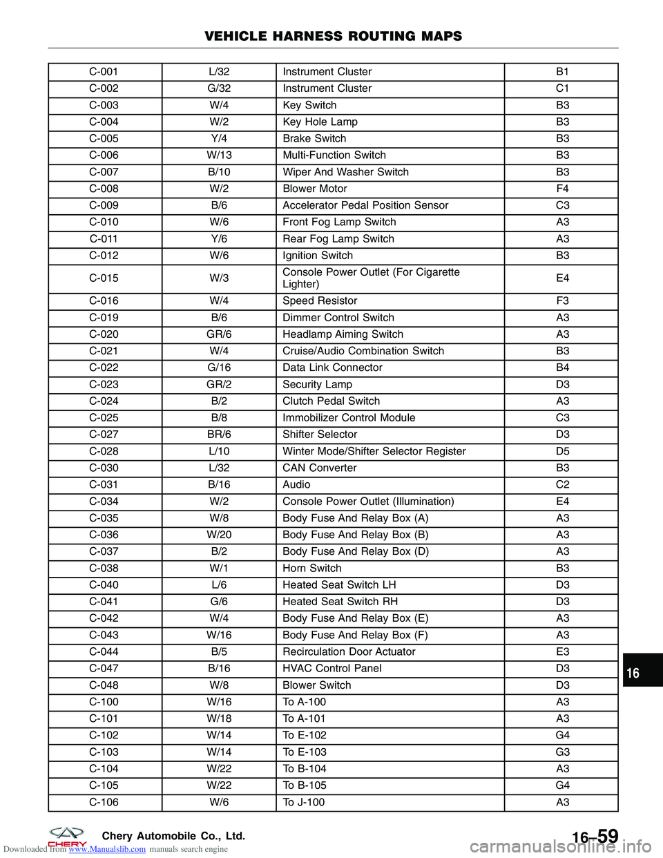
Downloaded from www.Manualslib.com manuals search engine C-001L/32 Instrument Cluster B1
C-002 G/32 Instrument Cluster C1
C-003 W/4 Key Switch B3
C-004 W/2 Key Hole Lamp B3
C-005 Y/4Brake Switch B3
C-006 W/13 Multi-Function Switch B3
C-007 B/10 Wiper And Washer Switch B3
C-008 W/2 Blower Motor F4
C-009 B/6Accelerator Pedal Position Sensor C3
C-010 W/6 Front Fog Lamp Switch A3
C-011 Y/6Rear Fog Lamp Switch A3
C-012 W/6 Ignition Switch B3
C-015 W/3Console Power Outlet (For Cigarette
Lighter) E4
C-016 W/4 Speed Resistor F3
C-019 B/6Dimmer Control Switch A3
C-020 GR/6 Headlamp Aiming Switch A3
C-021 W/4 Cruise/Audio Combination Switch B3
C-022 G/16 Data Link Connector B4
C-023 GR/2 Security Lamp D3
C-024 B/2Clutch Pedal Switch A3
C-025 B/8Immobilizer Control Module C3
C-027 BR/6 Shifter Selector D3
C-028 L/10 Winter Mode/Shifter Selector Register D5
C-030 L/32 CAN Converter B3
C-031 B/16 Audio C2
C-034 W/2 Console Power Outlet (Illumination) E4
C-035 W/8 Body Fuse And Relay Box (A) A3
C-036 W/20 Body Fuse And Relay Box (B) A3
C-037 B/2Body Fuse And Relay Box (D) A3
C-038 W/1 Horn Switch B3
C-040 L/6Heated Seat Switch LH D3
C-041 G/6Heated Seat Switch RH D3
C-042 W/4 Body Fuse And Relay Box (E) A3
C-043 W/16 Body Fuse And Relay Box (F) A3
C-044 B/5Recirculation Door Actuator E3
C-047 B/16 HVAC Control Panel D3
C-048 W/8 Blower Switch D3
C-100 W/16 To A-100 A3
C-101 W/18 To A-101 A3
C-102 W/14 To E-102 G4
C-103 W/14 To E-103 G3
C-104 W/22 To B-104 A3
C-105 W/22 To B-105 G4
C-106 W/6 To J-100 A3
VEHICLE HARNESS ROUTING MAPS
16
16–59Chery Automobile Co., Ltd.