2009 CHERY TIGGO light
[x] Cancel search: lightPage 1431 of 1903
Downloaded from www.Manualslib.com manuals search engine Operation
ABS Braking
•ABS operation is available at all vehicle speeds above 20 km/h. If a wheel locking tendency is detected during
a brake application, the brake system enters the ABS mode. During ABS braking, hydraulic pressure in the four
wheel circuits is modulated to prevent any wheel from locking. Each wheel circuit is designed with a set of
electric solenoids to allow modulation. The system can build and release pressure at each wheel, depending on
signals generated by the wheel speed sensors at each wheel and received at the ABS Module.
• There are a few performance characteristics of the ABS that may at first seem abnormal, but in fact are nor-
mal. These characteristics are described below.
� If the electrical system malfunctions, the Fail-Safe function is activated, the ABS becomes inoperative and
the ABS warning lamp turns on.
� During ABS operation, the brake pedal may vibrate lightly and a mechanical noise may be heard. This is normal.
� Stopping distance may be longer than that of vehicles without ABS when vehicle drives on rough, gravel, or snow-covered (fresh, deep snow) roads.
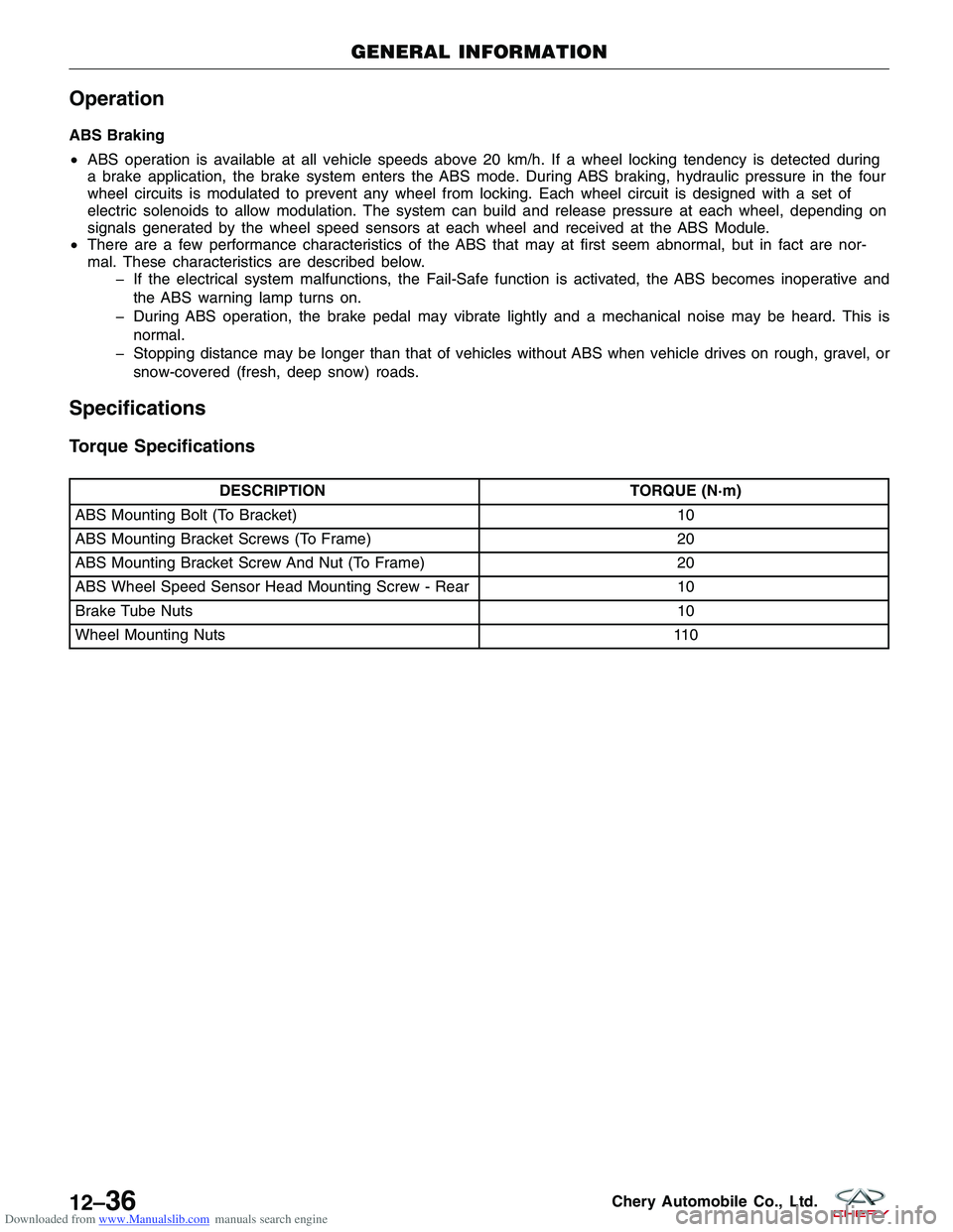
Specifications
Torque Specifications
DESCRIPTION TORQUE (N·m)
ABS Mounting Bolt (To Bracket) 10
ABS Mounting Bracket Screws (To Frame) 20
ABS Mounting Bracket Screw And Nut (To Frame) 20
ABS Wheel Speed Sensor Head Mounting Screw - Rear 10
Brake Tube Nuts 10
Wheel Mounting Nuts 110
GENERAL INFORMATION
12–36Chery Automobile Co., Ltd.
Page 1474 of 1903
Downloaded from www.Manualslib.com manuals search engine PARKING BRAKE
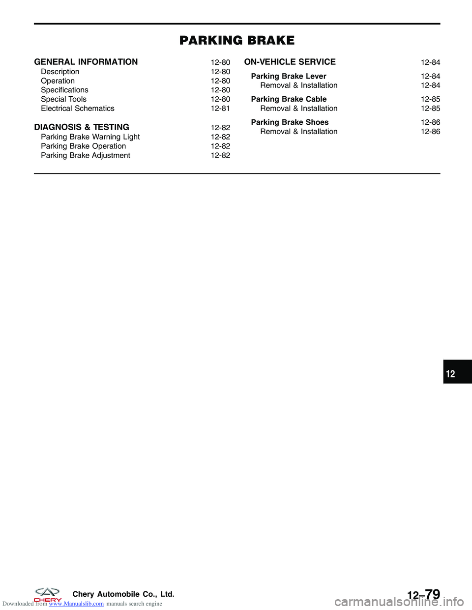
GENERAL INFORMATION12-80
Description 12-80
Operation 12-80
Specifications 12-80
Special Tools 12-80
Electrical Schematics 12-81
DIAGNOSIS & TESTING12-82
Parking Brake Warning Light 12-82
Parking Brake Operation 12-82
Parking Brake Adjustment 12-82
ON-VEHICLE SERVICE12-84
Parking Brake Lever 12-84
Removal & Installation 12-84
Parking Brake Cable 12-85
Removal & Installation 12-85
Parking Brake Shoes 12-86
Removal & Installation 12-86
12
12–79Chery Automobile Co., Ltd.
Page 1477 of 1903
Downloaded from www.Manualslib.com manuals search engine DIAGNOSIS & TESTING
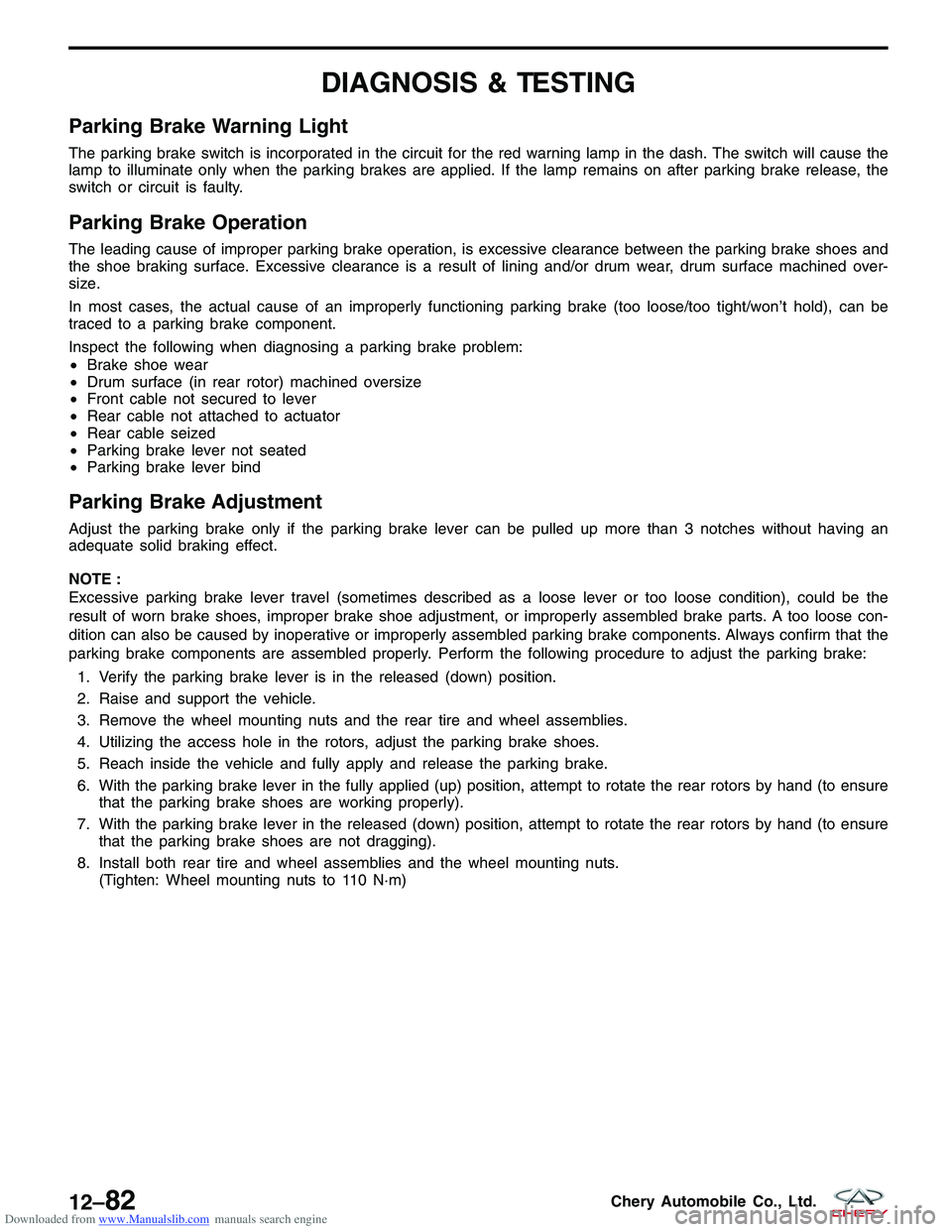
Parking Brake Warning Light
The parking brake switch is incorporated in the circuit for the red warning lamp in the dash. The switch will cause the
lamp to illuminate only when the parking brakes are applied. If the lamp remains on after parking brake release, the
switch or circuit is faulty.
Parking Brake Operation
The leading cause of improper parking brake operation, is excessive clearance between the parking brake shoes and
the shoe braking surface. Excessive clearance is a result of lining and/or drum wear, drum surface machined over-
size.
In most cases, the actual cause of an improperly functioning parking brake (too loose/too tight/won’t hold), can be
traced to a parking brake component.
Inspect the following when diagnosing a parking brake problem:
•Brake shoe wear
• Drum surface (in rear rotor) machined oversize
• Front cable not secured to lever
• Rear cable not attached to actuator
• Rear cable seized
• Parking brake lever not seated
• Parking brake lever bind
Parking Brake Adjustment
Adjust the parking brake only if the parking brake lever can be pulled up more than 3 notches without having an
adequate solid braking effect.
NOTE :
Excessive parking brake lever travel (sometimes described as a loose lever or too loose condition), could be the
result of worn brake shoes, improper brake shoe adjustment, or improperly assembled brake parts. A too loose con-
dition can also be caused by inoperative or improperly assembled parking brake components. Always confirm that the
parking brake components are assembled properly. Perform the following procedure to adjust the parking brake:
1. Verify the parking brake lever is in the released (down) position.
2. Raise and support the vehicle.
3. Remove the wheel mounting nuts and the rear tire and wheel assemblies.
4. Utilizing the access hole in the rotors, adjust the parking brake shoes.
5. Reach inside the vehicle and fully apply and release the parking brake.
6. With the parking brake lever in the fully applied (up) position, attempt to rotate the rear rotors by hand (to ensure that the parking brake shoes are working properly).
7. With the parking brake lever in the released (down) position, attempt to rotate the rear rotors by hand (to ensure that the parking brake shoes are not dragging).
8. Install both rear tire and wheel assemblies and the wheel mounting nuts. (Tighten: Wheel mounting nuts to 110 N·m)
12–82Chery Automobile Co., Ltd.
Page 1495 of 1903
Downloaded from www.Manualslib.com manuals search engine CONDITIONPOSSIBLE CAUSES CORRECTION
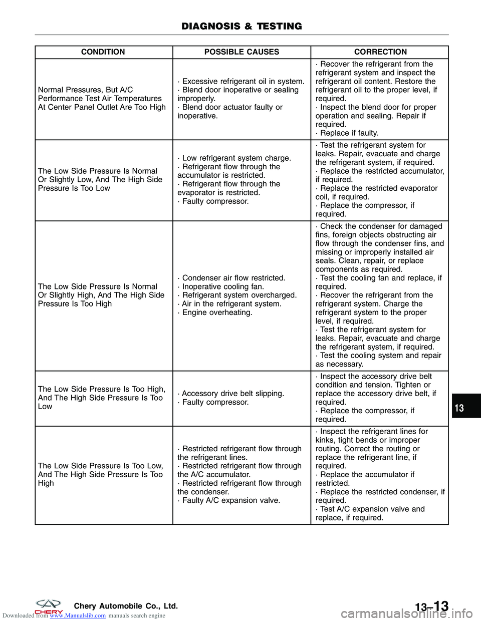
Normal Pressures, But A/C
Performance Test Air Temperatures
At Center Panel Outlet Are Too High · Excessive refrigerant oil in system.
· Blend door inoperative or sealing
improperly.
· Blend door actuator faulty or
inoperative.· Recover the refrigerant from the
refrigerant system and inspect the
refrigerant oil content. Restore the
refrigerant oil to the proper level, if
required.
· Inspect the blend door for proper
operation and sealing. Repair if
required.
· Replace if faulty.
The Low Side Pressure Is Normal
Or Slightly Low, And The High Side
Pressure Is Too Low · Low refrigerant system charge.
· Refrigerant flow through the
accumulator is restricted.
· Refrigerant flow through the
evaporator is restricted.
· Faulty compressor.· Test the refrigerant system for
leaks. Repair, evacuate and charge
the refrigerant system, if required.
· Replace the restricted accumulator,
if required.
· Replace the restricted evaporator
coil, if required.
· Replace the compressor, if
required.
The Low Side Pressure Is Normal
Or Slightly High, And The High Side
Pressure Is Too High · Condenser air flow restricted.
· Inoperative cooling fan.
· Refrigerant system overcharged.
· Air in the refrigerant system.
· Engine overheating.· Check the condenser for damaged
fins, foreign objects obstructing air
flow through the condenser fins, and
missing or improperly installed air
seals. Clean, repair, or replace
components as required.
· Test the cooling fan and replace, if
required.
· Recover the refrigerant from the
refrigerant system. Charge the
refrigerant system to the proper
level, if required.
· Test the refrigerant system for
leaks. Repair, evacuate and charge
the refrigerant system, if required.
· Test the cooling system and repair
as necessary.
The Low Side Pressure Is Too High,
And The High Side Pressure Is Too
Low · Accessory drive belt slipping.
· Faulty compressor.· Inspect the accessory drive belt
condition and tension. Tighten or
replace the accessory drive belt, if
required.
· Replace the compressor, if
required.
The Low Side Pressure Is Too Low,
And The High Side Pressure Is Too
High · Restricted refrigerant flow through
the refrigerant lines.
· Restricted refrigerant flow through
the A/C accumulator.
· Restricted refrigerant flow through
the condenser.
· Faulty A/C expansion valve.· Inspect the refrigerant lines for
kinks, tight bends or improper
routing. Correct the routing or
replace the refrigerant line, if
required.
· Replace the accumulator if
restricted.
· Replace the restricted condenser, if
required.
· Test A/C expansion valve and
replace, if required.
DIAGNOSIS & TESTING
13
13–13Chery Automobile Co., Ltd.
Page 1496 of 1903
Downloaded from www.Manualslib.com manuals search engine Heater Performance
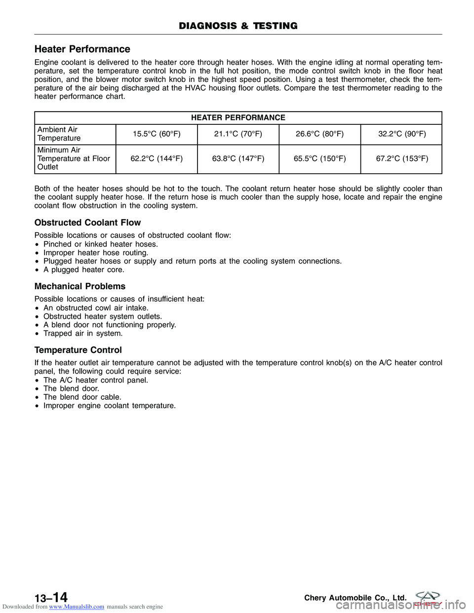
Engine coolant is delivered to the heater core through heater hoses. With the engine idling at normal operating tem-
perature, set the temperature control knob in the full hot position, the mode control switch knob in the floor heat
position, and the blower motor switch knob in the highest speed position. Using a test thermometer, check the tem-
perature of the air being discharged at the HVAC housing floor outlets. Compare the test thermometer reading to the
heater performance chart.
HEATER PERFORMANCE
Ambient Air
Temperature 15.5°C (60°F) 21.1°C (70°F) 26.6°C (80°F) 32.2°C (90°F)
Minimum Air
Temperature at Floor
Outlet 62.2°C (144°F) 63.8°C (147°F) 65.5°C (150°F) 67.2°C (153°F)
Both of the heater hoses should be hot to the touch. The coolant return heater hose should be slightly cooler than
the coolant supply heater hose. If the return hose is much cooler than the supply hose, locate and repair the engine
coolant flow obstruction in the cooling system.
Obstructed Coolant Flow
Possible locations or causes of obstructed coolant flow:
• Pinched or kinked heater hoses.
• Improper heater hose routing.
• Plugged heater hoses or supply and return ports at the cooling system connections.
• A plugged heater core.
Mechanical Problems
Possible locations or causes of insufficient heat:
•An obstructed cowl air intake.
• Obstructed heater system outlets.
• A blend door not functioning properly.
• Trapped air in system.
Temperature Control
If the heater outlet air temperature cannot be adjusted with the temperature control knob(s) on the A/C heater control
panel, the following could require service:
•The A/C heater control panel.
• The blend door.
• The blend door cable.
• Improper engine coolant temperature.
DIAGNOSIS & TESTING
13–14Chery Automobile Co., Ltd.
Page 1504 of 1903
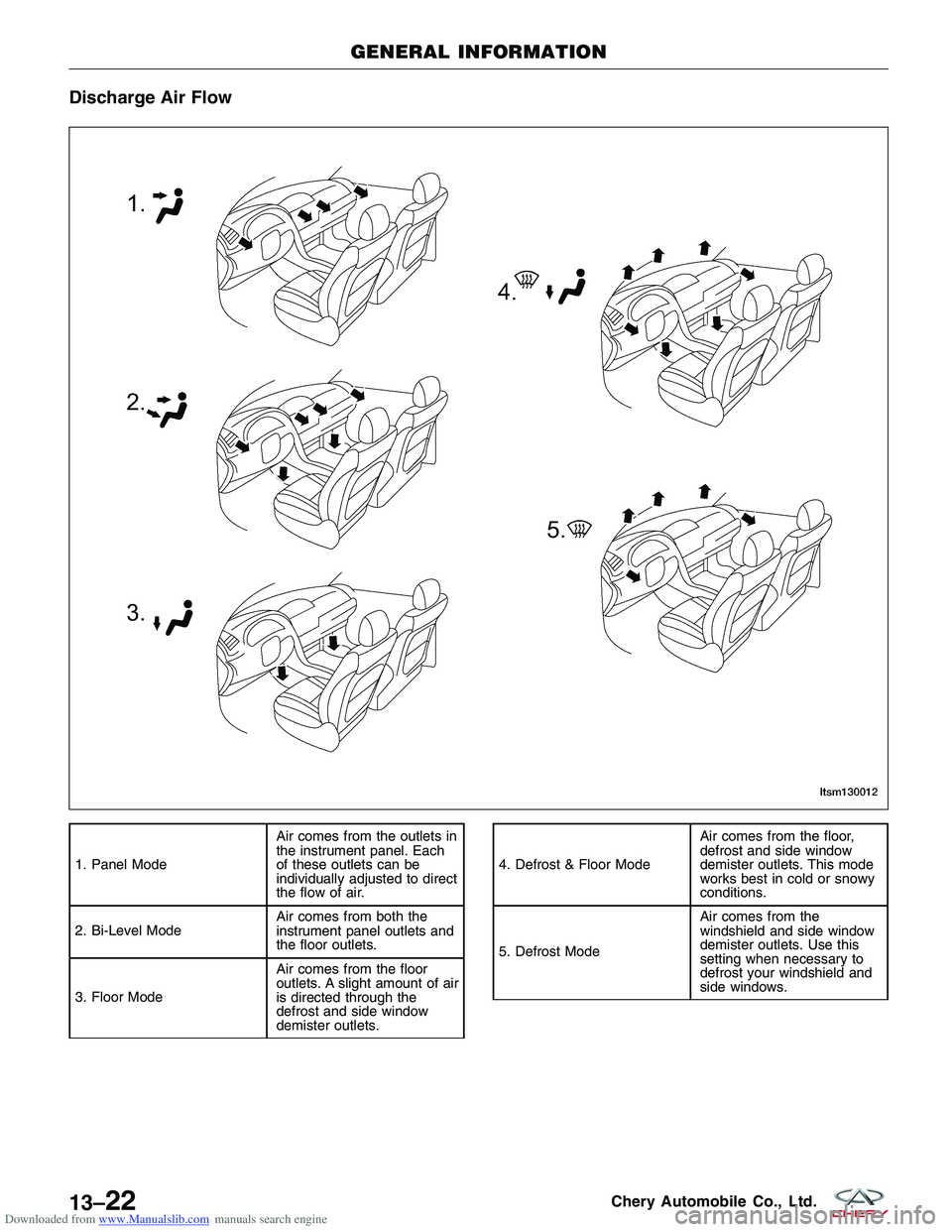
Downloaded from www.Manualslib.com manuals search engine Discharge Air Flow
1. Panel ModeAir comes from the outlets in
the instrument panel. Each
of these outlets can be
individually adjusted to direct
the flow of air.
2. Bi-Level Mode Air comes from both the
instrument panel outlets and
the floor outlets.
3. Floor Mode Air comes from the floor
outlets. A slight amount of air
is directed through the
defrost and side window
demister outlets.4. Defrost & Floor ModeAir comes from the floor,
defrost and side window
demister outlets. This mode
works best in cold or snowy
conditions.
5. Defrost Mode Air comes from the
windshield and side window
demister outlets. Use this
setting when necessary to
defrost your windshield and
side windows.
GENERAL INFORMATION
LTSM130012
13–22Chery Automobile Co., Ltd.
Page 1622 of 1903
Downloaded from www.Manualslib.com manuals search engine BODY CONTROL MODULE - BCM
Description
The Body Control Module (BCM) is located behind the glove box. The BCM controls many electrical components and
systems for the vehicle electrical system. The BCM is the primary hub that controls functions such as internal and
external lighting, power windows and power door locks.
Operation
The Body Control Module (BCM) uses hard wired inputs from various sensors and switches. The sensors and
switches are located throughout the vehicle.
The following components are inputs to the BCM:
•Key switch
• Rear defroster switch
• Hazard lamp switch
• Power window switches
• Power door lock switches
• Seat belt switch
• Vehicle speed
• Door ajar switches
• Turn signal switch
The following components are outputs from the BCM:
• Key lamp
• Stop lamp relay
• Rear defroster grid
• Courtesy lamps
• Power window motor
• Power door lock motor
• Turn signal lamps
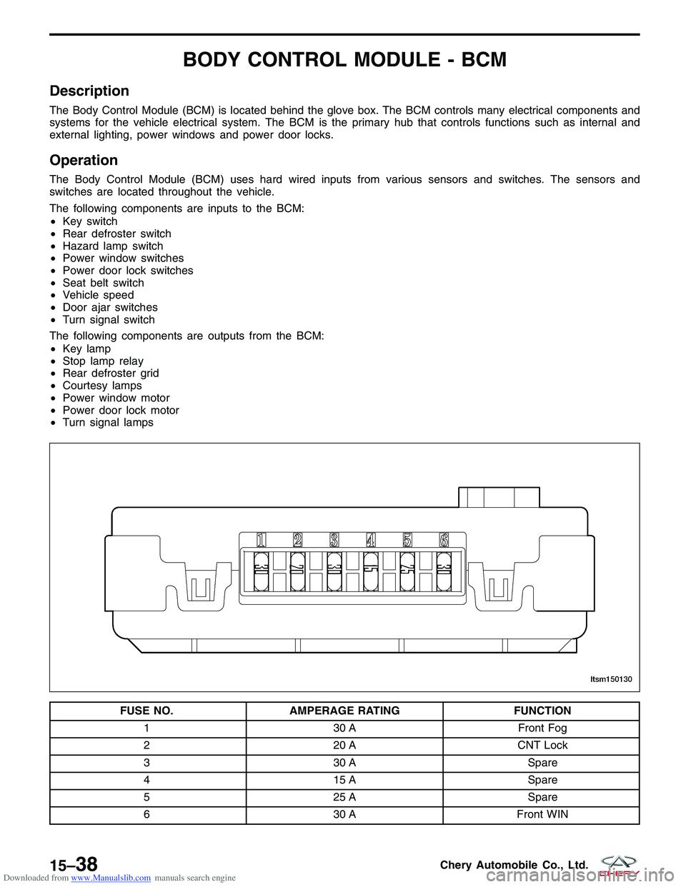
FUSE NO. AMPERAGE RATING FUNCTION
1 30 AFront Fog
2 20 ACNT Lock
3 30 A Spare
4 15 A Spare
5 25 A Spare
6 30 AFront WIN
LTSM150130
15–38Chery Automobile Co., Ltd.
Page 1636 of 1903
Downloaded from www.Manualslib.com manuals search engine INSTRUMENT CLUSTER
Description
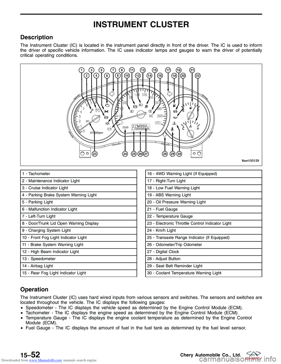
The Instrument Cluster (IC) is located in the instrument panel directly in front of the driver. The IC is used to inform
the driver of specific vehicle information. The IC uses indicator lamps and gauges to warn the driver of potentially
critical operating conditions.
Operation
The Instrument Cluster (IC) uses hard wired inputs from various sensors and switches. The sensors and switches are
located throughout the vehicle. The IC displays the following gauges:
•Speedometer - The IC displays the vehicle speed as determined by the Engine Control Module (ECM).
• Tachometer - The IC displays the engine speed as determined by the Engine Control Module (ECM).
• Temperature Gauge - The IC displays the engine coolant temperature as determined by the Engine Control
Module (ECM).
• Fuel Gauge - The IC displays the amount of fuel in the fuel tank as determined by the fuel level sensor.
1 - Tachometer
2 - Maintenance Indicator Light
3 - Cruise Indicator Light
4 - Parking Brake System Warning Light
5 - Parking Light
6 - Malfunction Indicator Light
7 - Left-Turn Light
8 - Door/Trunk Lid Open Warning Display
9 - Charging System Light
10 - Front Fog Light Indicator Light
11 - Brake System Warning Light
12 - High Beam Indicator Light
13 - Speedometer
14 - Airbag Light
15 - Rear Fog Light Indicator Light16 - 4WD Warning Light (If Equipped)
17 - Right-Turn Light
18 - Low Fuel Warning Light
19 - ABS Warning Light
20 - Oil Pressure Warning Light
21 - Fuel Gauge
22 - Temperature Gauge
23 - Electronic Throttle Control Indicator Light
24 - Km/h Light
25 - Transaxle Range Indicator (If Equipped)
26 - Odometer/Trip Odometer
27 - Digital Clock
28 - Adjust Button
29 - Seat Belt Reminder Light
30 - Coolant Temperature Warning Light
LTSM150129
15–52Chery Automobile Co., Ltd.