2009 CHERY TIGGO light
[x] Cancel search: lightPage 1241 of 1903
Downloaded from www.Manualslib.com manuals search engine Assemble
Assemble in the reverse order of disassembly.
NOTE :
•Check and ensure the shift fork is properly installed to the fork shaft, there should be NO axial or radial motion in
the fork shaft.
• Check and ensure the fork rack is properly installed to the fork shaft, there should be NO axial or radial motion in
the fork shaft.
• Check and ensure backup light driving block is properly installed to the fork shaft, there should be NO axial or
radial motion in the fork shaft.
• Check the fork shaft surface for any damage.
• Check the position of the three spring pins, ensure the pins are in proper alignment. The extension of both ends
of the three spring pins should not exceed 3 mm.
3rd-4th Gear Shift Fork
Disassemble
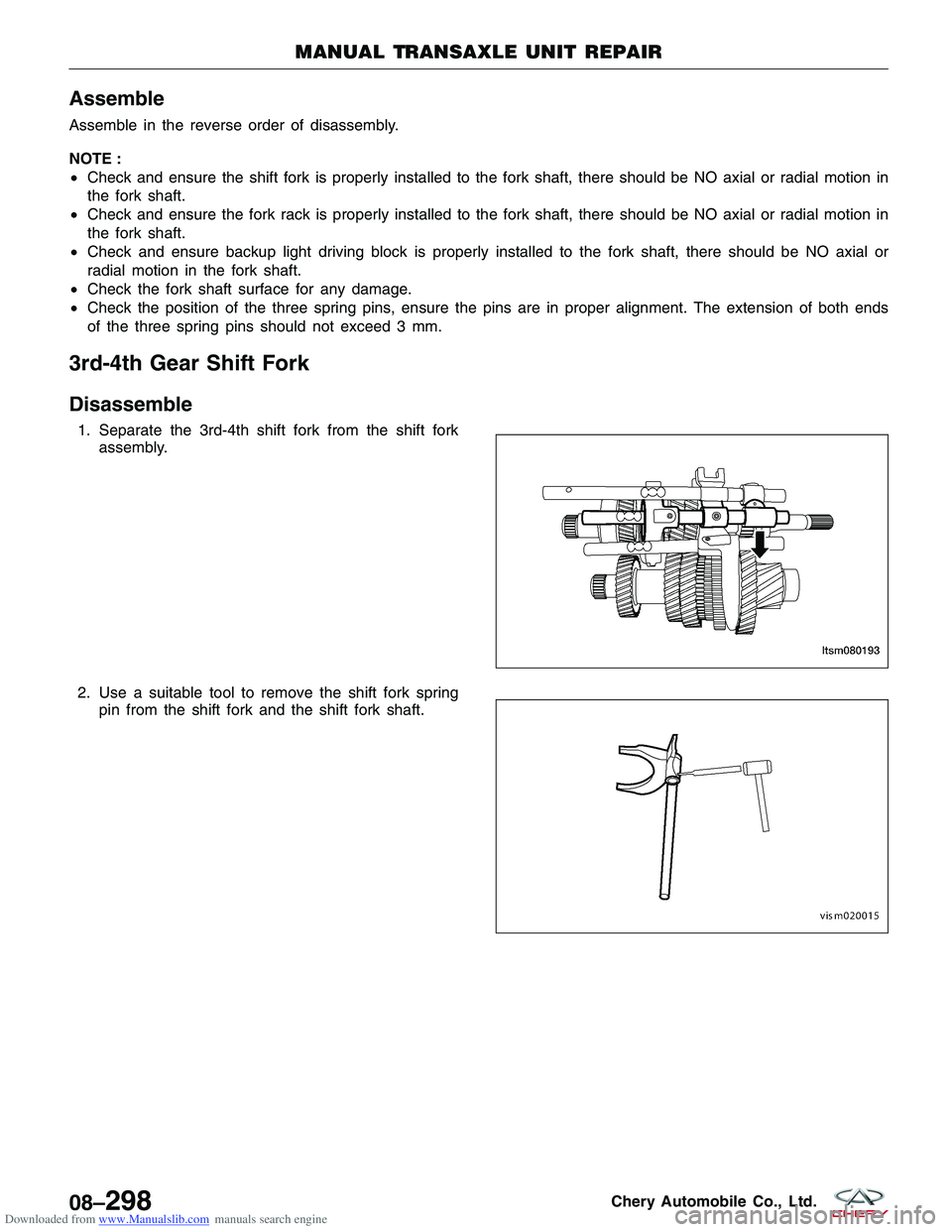
1. Separate the 3rd-4th shift fork from the shift fork
assembly.
2. Use a suitable tool to remove the shift fork spring pin from the shift fork and the shift fork shaft.
MANUAL TRANSAXLE UNIT REPAIR
LTSM080193
VISM020015
08–298Chery Automobile Co., Ltd.
Page 1359 of 1903
Downloaded from www.Manualslib.com manuals search engine DIAGNOSIS & TESTING
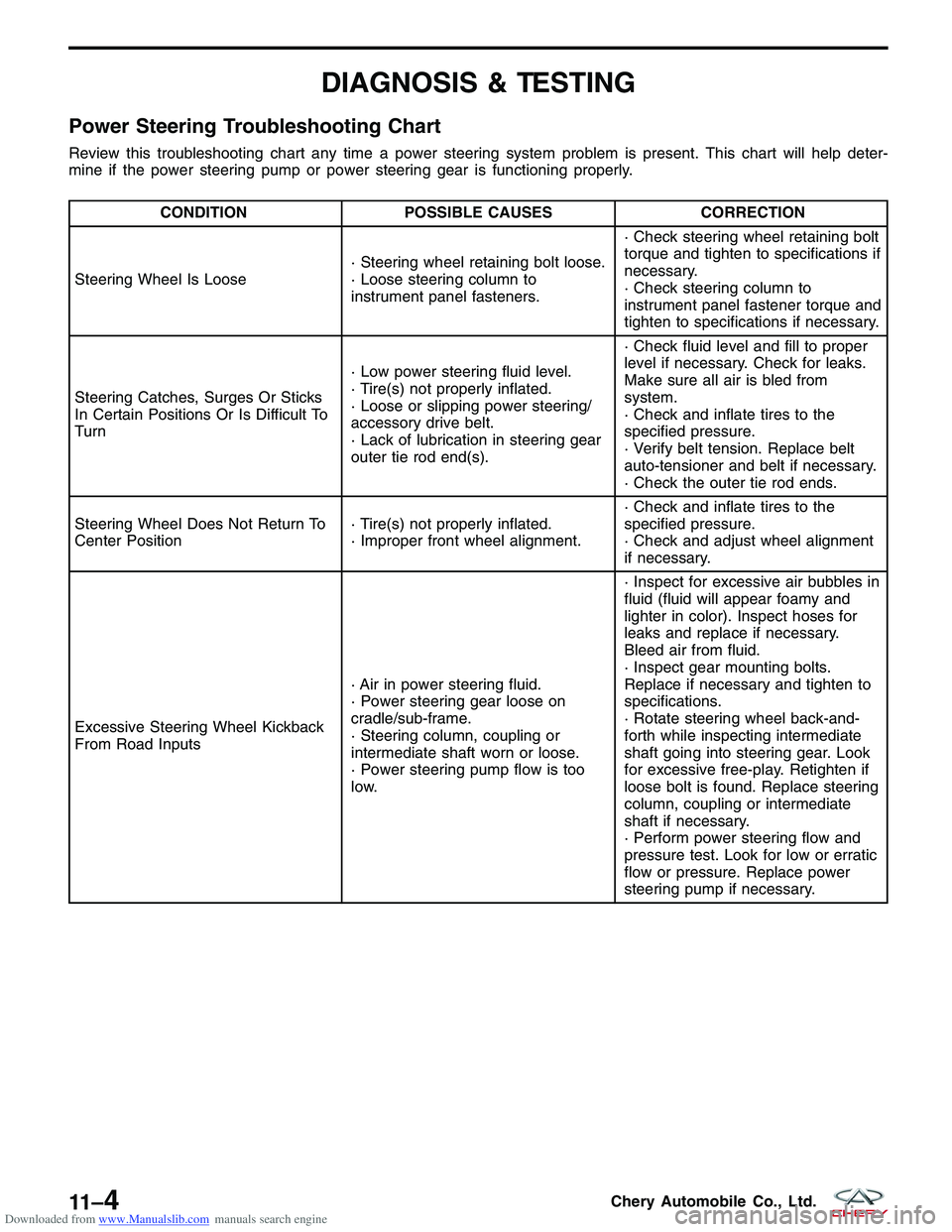
Power Steering Troubleshooting Chart
Review this troubleshooting chart any time a power steering system problem is present. This chart will help deter-
mine if the power steering pump or power steering gear is functioning properly.
CONDITIONPOSSIBLE CAUSES CORRECTION
Steering Wheel Is Loose · Steering wheel retaining bolt loose.
· Loose steering column to
instrument panel fasteners.· Check steering wheel retaining bolt
torque and tighten to specifications if
necessary.
· Check steering column to
instrument panel fastener torque and
tighten to specifications if necessary.
Steering Catches, Surges Or Sticks
In Certain Positions Or Is Difficult To
Turn · Low power steering fluid level.
· Tire(s) not properly inflated.
· Loose or slipping power steering/
accessory drive belt.
· Lack of lubrication in steering gear
outer tie rod end(s).· Check fluid level and fill to proper
level if necessary. Check for leaks.
Make sure all air is bled from
system.
· Check and inflate tires to the
specified pressure.
· Verify belt tension. Replace belt
auto-tensioner and belt if necessary.
· Check the outer tie rod ends.
Steering Wheel Does Not Return To
Center Position · Tire(s) not properly inflated.
· Improper front wheel alignment.· Check and inflate tires to the
specified pressure.
· Check and adjust wheel alignment
if necessary.
Excessive Steering Wheel Kickback
From Road Inputs · Air in power steering fluid.
· Power steering gear loose on
cradle/sub-frame.
· Steering column, coupling or
intermediate shaft worn or loose.
· Power steering pump flow is too
low.· Inspect for excessive air bubbles in
fluid (fluid will appear foamy and
lighter in color). Inspect hoses for
leaks and replace if necessary.
Bleed air from fluid.
· Inspect gear mounting bolts.
Replace if necessary and tighten to
specifications.
· Rotate steering wheel back-and-
forth while inspecting intermediate
shaft going into steering gear. Look
for excessive free-play. Retighten if
loose bolt is found. Replace steering
column, coupling or intermediate
shaft if necessary.
· Perform power steering flow and
pressure test. Look for low or erratic
flow or pressure. Replace power
steering pump if necessary.
11 –4Chery Automobile Co., Ltd.
Page 1368 of 1903
Downloaded from www.Manualslib.com manuals search engine Inspection - Steering System
Steering Wheel Free-Play Inspection
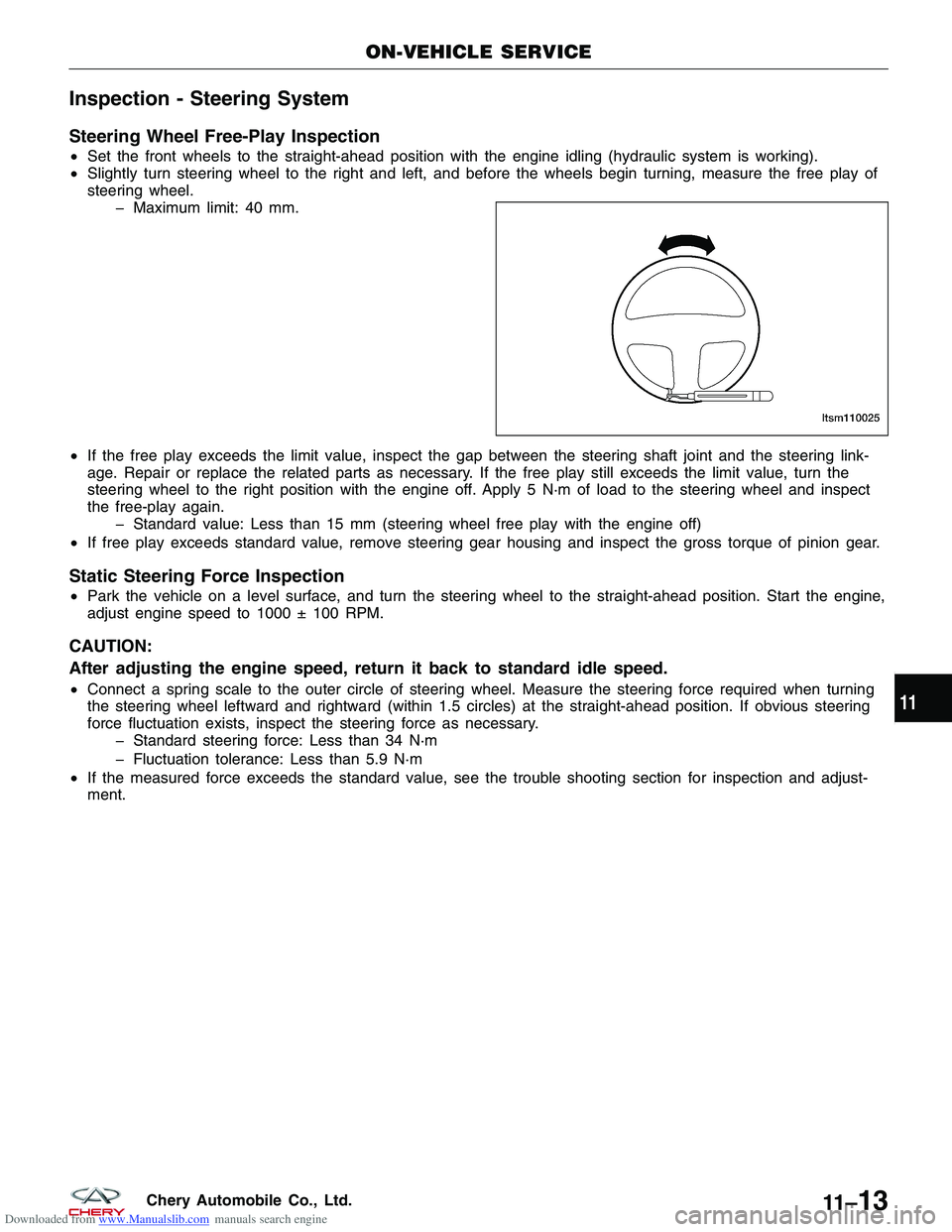
•Set the front wheels to the straight-ahead position with the engine idling (hydraulic system is working).
• Slightly turn steering wheel to the right and left, and before the wheels begin turning, measure the free play of
steering wheel.
� Maximum limit: 40 mm.
• If the free play exceeds the limit value, inspect the gap between the steering shaft joint and the steering link-
age. Repair or replace the related parts as necessary. If the free play still exceeds the limit value, turn the
steering wheel to the right position with the engine off. Apply 5 N·m of load to the steering wheel and inspect
the free-play again.
� Standard value: Less than 15 mm (steering wheel free play with the engine off)
• If free play exceeds standard value, remove steering gear housing and inspect the gross torque of pinion gear.
Static Steering Force Inspection
•Park the vehicle on a level surface, and turn the steering wheel to the straight-ahead position. Start the engine,
adjust engine speed to 1000 ± 100 RPM.
CAUTION:
After adjusting the engine speed, return it back to standard idle speed.
•Connect a spring scale to the outer circle of steering wheel. Measure the steering force required when turning
the steering wheel leftward and rightward (within 1.5 circles) at the straight-ahead position. If obvious steering
force fluctuation exists, inspect the steering force as necessary.
� Standard steering force: Less than 34 N·m
� Fluctuation tolerance: Less than 5.9 N·m
• If the measured force exceeds the standard value, see the trouble shooting section for inspection and adjust-
ment.
ON-VEHICLE SERVICE
LTSM110025
11
11 –13Chery Automobile Co., Ltd.
Page 1402 of 1903
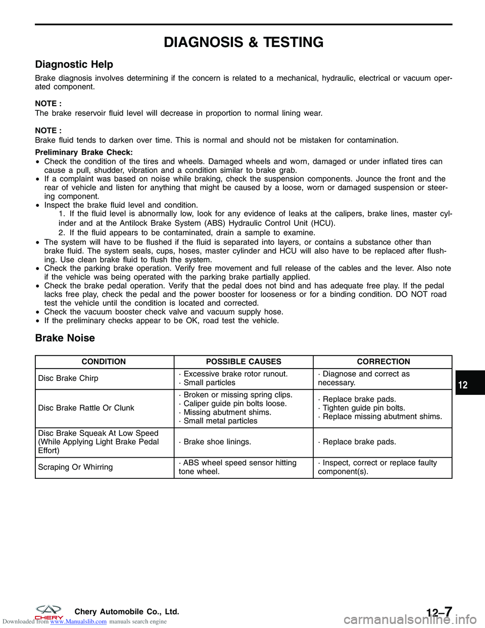
Downloaded from www.Manualslib.com manuals search engine DIAGNOSIS & TESTING
Diagnostic Help
Brake diagnosis involves determining if the concern is related to a mechanical, hydraulic, electrical or vacuum oper-
ated component.
NOTE :
The brake reservoir fluid level will decrease in proportion to normal lining wear.
NOTE :
Brake fluid tends to darken over time. This is normal and should not be mistaken for contamination.
Preliminary Brake Check:
•Check the condition of the tires and wheels. Damaged wheels and worn, damaged or under inflated tires can
cause a pull, shudder, vibration and a condition similar to brake grab.
• If a complaint was based on noise while braking, check the suspension components. Jounce the front and the
rear of vehicle and listen for anything that might be caused by a loose, worn or damaged suspension or steer-
ing component.
• Inspect the brake fluid level and condition.
1. If the fluid level is abnormally low, look for any evidence of leaks at the calipers, brake lines, master cyl-
inder and at the Antilock Brake System (ABS) Hydraulic Control Unit (HCU).
2. If the fluid appears to be contaminated, drain a sample to examine.
• The system will have to be flushed if the fluid is separated into layers, or contains a substance other than
brake fluid. The system seals, cups, hoses, master cylinder and HCU will also have to be replaced after flush-
ing. Use clean brake fluid to flush the system.
• Check the parking brake operation. Verify free movement and full release of the cables and the lever. Also note
if the vehicle was being operated with the parking brake partially applied.
• Check the brake pedal operation. Verify that the pedal does not bind and has adequate free play. If the pedal
lacks free play, check the pedal and the power booster for looseness or for a binding condition. DO NOT road
test the vehicle until the condition is located and corrected.
• Check the vacuum booster check valve and vacuum supply hose.
• If the preliminary checks appear to be OK, road test the vehicle.
Brake Noise
CONDITION POSSIBLE CAUSES CORRECTION
Disc Brake Chirp · Excessive brake rotor runout.
· Small particles· Diagnose and correct as
necessary.
Disc Brake Rattle Or Clunk · Broken or missing spring clips.
· Caliper guide pin bolts loose.
· Missing abutment shims.
· Small metal particles· Replace brake pads.
· Tighten guide pin bolts.
· Replace missing abutment shims.
Disc Brake Squeak At Low Speed
(While Applying Light Brake Pedal
Effort) · Brake shoe linings.
· Replace brake pads.
Scraping Or Whirring · ABS wheel speed sensor hitting
tone wheel.· Inspect, correct or replace faulty
component(s).
12
12–7Chery Automobile Co., Ltd.
Page 1416 of 1903
Downloaded from www.Manualslib.com manuals search engine Front Brake Rotor
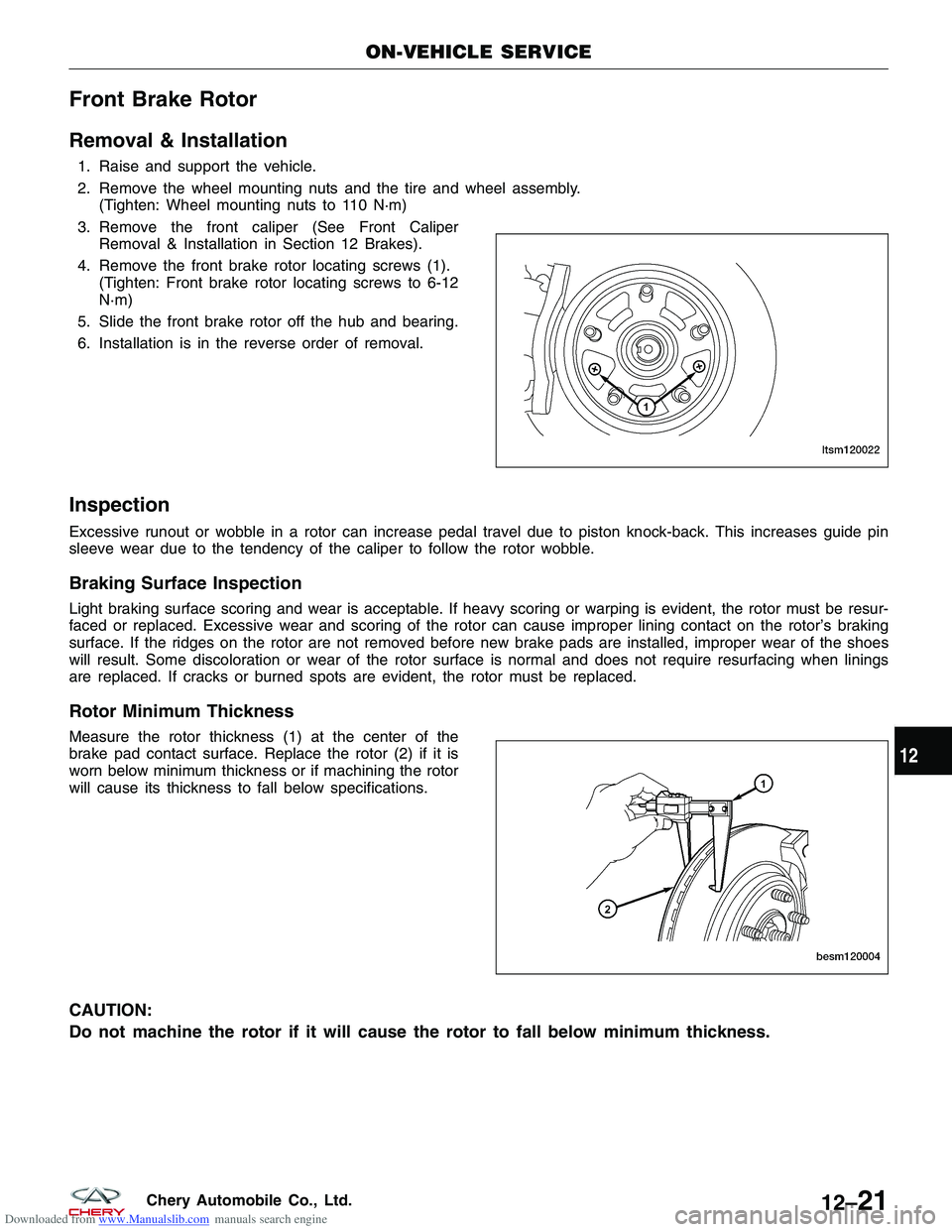
Removal & Installation
1. Raise and support the vehicle.
2. Remove the wheel mounting nuts and the tire and wheel assembly.(Tighten: Wheel mounting nuts to 110 N·m)
3. Remove the front caliper (See Front Caliper Removal & Installation in Section 12 Brakes).
4. Remove the front brake rotor locating screws (1). (Tighten: Front brake rotor locating screws to 6-12
N·m)
5. Slide the front brake rotor off the hub and bearing.
6. Installation is in the reverse order of removal.
Inspection
Excessive runout or wobble in a rotor can increase pedal travel due to piston knock-back. This increases guide pin
sleeve wear due to the tendency of the caliper to follow the rotor wobble.
Braking Surface Inspection
Light braking surface scoring and wear is acceptable. If heavy scoring or warping is evident, the rotor must be resur-
faced or replaced. Excessive wear and scoring of the rotor can cause improper lining contact on the rotor’s braking
surface. If the ridges on the rotor are not removed before new brake pads are installed, improper wear of the shoes
will result. Some discoloration or wear of the rotor surface is normal and does not require resurfacing when linings
are replaced. If cracks or burned spots are evident, the rotor must be replaced.
Rotor Minimum Thickness
Measure the rotor thickness (1) at the center of the
brake pad contact surface. Replace the rotor (2) if it is
worn below minimum thickness or if machining the rotor
will cause its thickness to fall below specifications.
CAUTION:
Do not machine the rotor if it will cause the rotor to fall below minimum thickness.
ON-VEHICLE SERVICE
LTSM120022
BESM120004
12
12–21Chery Automobile Co., Ltd.
Page 1417 of 1903
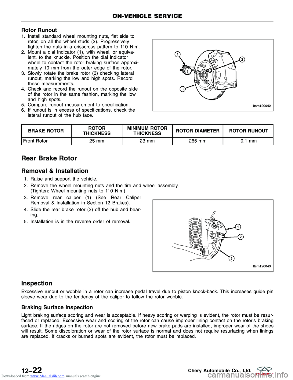
Downloaded from www.Manualslib.com manuals search engine Rotor Runout
1. Install standard wheel mounting nuts, flat side torotor, on all the wheel studs (2). Progressively
tighten the nuts in a crisscross pattern to 110 N·m.
2. Mount a dial indicator (1), with wheel, or equiva- lent, to the knuckle. Position the dial indicator
wheel to contact the rotor braking surface approxi-
mately 10 mm from the outer edge of the rotor.
3. Slowly rotate the brake rotor (3) checking lateral runout, marking the low and high spots. Record
these measurements.
4. Check and record the runout on the opposite side of the rotor in the same fashion, marking the low
and high spots.
5. Compare runout measurement to specification.
6. If runout is in excess of specifications, check the lateral runout of the hub face.
BRAKE ROTOR ROTOR
THICKNESS MINIMUM ROTOR
THICKNESS ROTOR DIAMETER ROTOR RUNOUT
Front Rotor 25 mm23 mm265 mm 0.1 mm
Rear Brake Rotor
Removal & Installation
1. Raise and support the vehicle.
2. Remove the wheel mounting nuts and the tire and wheel assembly.
(Tighten: Wheel mounting nuts to 110 N·m)
3. Remove rear caliper (1) (See Rear Caliper Removal & Installation in Section 12 Brakes).
4. Slide the rear brake rotor (3) off the hub and bear- ing.
5. Installation is in the reverse order of removal.
Inspection
Excessive runout or wobble in a rotor can increase pedal travel due to piston knock-back. This increases guide pin
sleeve wear due to the tendency of the caliper to follow the rotor wobble.
Braking Surface Inspection
Light braking surface scoring and wear is acceptable. If heavy scoring or warping is evident, the rotor must be resur-
faced or replaced. Excessive wear and scoring of the rotor can cause improper lining contact on the rotor’s braking
surface. If the ridges on the rotor are not removed before new brake pads are installed, improper wear of the shoes
will result. Some discoloration or wear of the rotor surface is normal and does not require resurfacing when linings
are replaced. If cracks or burned spots are evident, the rotor must be replaced.
ON-VEHICLE SERVICE
LTSM120042
LTSM120043
12–22Chery Automobile Co., Ltd.
Page 1423 of 1903
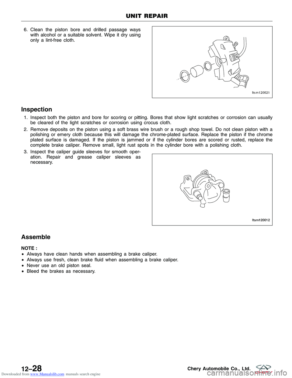
Downloaded from www.Manualslib.com manuals search engine 6. Clean the piston bore and drilled passage wayswith alcohol or a suitable solvent. Wipe it dry using
only a lint-free cloth.
Inspection
1. Inspect both the piston and bore for scoring or pitting. Bores that show light scratches or corrosion can usuallybe cleared of the light scratches or corrosion using crocus cloth.
2. Remove deposits on the piston using a soft brass wire brush or a rough shop towel. Do not clean piston with a polishing or emery cloth because this will damage the chrome-plated surface. Replace the piston if the chrome
plated surface is damaged. If the piston is jammed or if the cylinder bores are scored or rusted, replace the
complete brake caliper. Remove small, light rust spots in the cylinder bore with a polishing cloth.
3. Inspect the caliper guide sleeves for smooth oper- ation. Repair and grease caliper sleeves as
necessary.
Assemble
NOTE :
•Always have clean hands when assembling a brake caliper.
• Always use fresh, clean brake fluid when assembling a brake caliper.
• Never use an old piston seal.
• Bleed the brakes as necessary.
UNIT REPAIR
LTSM120021
LTSM120012
12–28Chery Automobile Co., Ltd.
Page 1426 of 1903
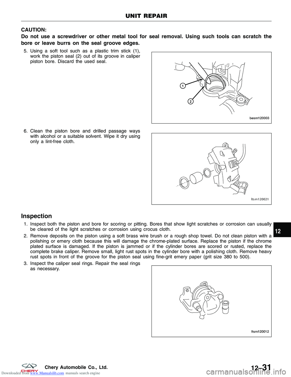
Downloaded from www.Manualslib.com manuals search engine CAUTION:
Do not use a screwdriver or other metal tool for seal removal. Using such tools can scratch the
bore or leave burrs on the seal groove edges.
5. Using a soft tool such as a plastic trim stick (1),work the piston seal (2) out of its groove in caliper
piston bore. Discard the used seal.
6. Clean the piston bore and drilled passage ways with alcohol or a suitable solvent. Wipe it dry using
only a lint-free cloth.
Inspection
1. Inspect both the piston and bore for scoring or pitting. Bores that show light scratches or corrosion can usuallybe cleared of the light scratches or corrosion using crocus cloth.
2. Remove deposits on the piston using a soft brass wire brush or a rough shop towel. Do not clean piston with a polishing or emery cloth because this will damage the chrome-plated surface. Replace the piston if the chrome
plated surface is damaged. If the piston is jammed or if the cylinder bores are scored or rusted, replace the
complete brake caliper. Remove small, light rust spots in the cylinder bore with a polishing cloth. Remove heavy
rust spots in front of the groove for the piston seal using fine-grit emery paper (grit size 380 to 500).
3. Inspect the caliper seal rings. Repair the seal rings as necessary.
UNIT REPAIR
BESM120003
LTSM120021
LTSM120012
12
12–31Chery Automobile Co., Ltd.