Page 369 of 408

________________________________________________ E_ m ___ e_r.::g ~e ___ n_c ~y:.- s;_ i_t _u :...:a:..:. t.:.: i...:o :...:n...:..:. s _ __,J_
& WARNING !continued)
• Before you check anything in the engine compartment, always
read and heed all WARNINGS~ page 301, "Engine compartment".
0 Note
• Applying a higher voltage booster battery will cause expensive
damage to sensitive electronic components, such as control units,
relays, radio, etc .
• There must be no electrical contact between the vehicles as
otherwise current could already start to flow as soon as the positive
(+) terminals are connected.
[ i) Tips
• The discharged battery must be properly connected to the
vehicle's electrical system. When jump starting or charging the
battery , never connect the negative ground cable to the battery
negative post because the battery manager system must be able to
detect the battery's state of charge. Always connect the negative
ground cable to the negative ground post of the battery manager
control unit .•
Use of jumper cables
Make sure to connect the jumper cable clamps in exactly
the order described below!
Fig. 299 Jump starting
with the battery of
another vehicle: A -
discharged vehicle
battery, B -booster
battery
The procedure described below for connecting jumper
cables is intended to provide a jump start for your vehicle.
Vehicle with discharged battery:
-Turn off lights and accessories, move lever of automatic
transmission to
N (Neutral) or P (Park) and set parking
brake.
Connect POSITIVE (+) to POSITIVE (+) (red)
1. Connect one end to the positive terminal~ fig . 299 G)
of your battery @.
2. Connect the other end to the positive terminal
@ of the
booster battery
@.
Connect NEGATIVE (-) to NEGATIVE (-) (black)
3. Connect one end to the negative terminal @ of the
booster battery
@.
Vehicle care Do-it-yourself service irechnical data
Page 370 of 408

111!1.___E_ m_ e_r -=g :...e_ n _ c-=y _ s_ i_t _u _a _t_ i_o _n_ s _______________________________________________ _
4. Connect the other end t o the negative ground post of t he
battery manager contro l un it located next to t he batte ry.
Start in g the engin e
-Start the engine of the vehicle with the booster battery .
Run the engine at a moderate speed.
- Start eng ine w ith discharged ve hicle battery in t he usual
manner .
- If the e ngine fa ils to sta rt: do not keep the starter
cranking for longer than 10 seconds . Wait for about 30
seconds and then try aga in .
- With e ngine running, remove jumper cables from both
ve hic les in the exac t
reverse order.
The battery is vented to the outside to prevent gases from entering
the vehicle interior . Make sure that the jumper clamps are well
connected with their metal parts in full contact with the battery
termina ls .
& WARNING
To avo id seri ous pe rsonal injur y and d am age to the veh icle, heed
all warning s and ins truct ion s of the jumper cable manufa cturer . If
in doubt , call for road ser vic e.
• Jump er cable s mu st be long enough so that the vehicle s do not
tou ch .
• When connecting jumper c able s, make sure th at the y cannot
g et ca ught in an y mov ing par ts in the engine compa rt me nt.
• Befor e you che ck anything i n the en gine com partment , alwa ys
re ad and heed all WARNINGS=>
page 301 , "Engin e com partm ent ".
0 Note
Improper hook -up of jumper cables can ruin the generator. •
Always connect POS ITIVE( +) to POSITIVE(+), and NEGAT IVE( -) to
NEGAT IVE( -) ground post of the battery manager con trol unit.
• Check that al l screw plugs on the battery cells are screwed in
firm ly . If not, tighten plugs prior to connecting clamp on negative
battery terminal.
• Please note that the procedure for connect ing a jumper cable as
described above applies specifical ly to the case of your vehicle
being jump started. When you are giving a jump start to another
vehicle, do not connect the negative(-) cable to the negative(-)
t erminal on the discharged battery@=> page 367, fig. 299. Ins tead,
securely connect the negative (-l cable to either a solid meta l
component that is firmly bo lted to the engine block or to the engine
block itself. If the battery that is being charged does not vent to the
outside, escap ing battery gas could ignite and explode! •
Emergency towing with commercial
tow truck
General hints
Your Audi requires special handling for t owing.
T he fol lowing information is to be used by commercial tow truck
operators who know how to operate their equipment safely .
• Never t ow y our Audi , tow ing w ill ca use damage to t he en gin e
and tran sm iss ion .
• Never w ra p the safe ty c hai ns or winch ca bles a ro und th e bra ke
line s.
• To prevent un nece ssa ry d ama ge, your Audi must b e tr ansported
wi th a flat bed tru ck .
• To lo ad the vehi cle on to th e flat bed , us e the to wing loop fo und
in the vehicle tool s and a tt ac h to the front or rear anchorage
=> page 369 and=> page 370 . ~
Page 371 of 408

________________________________________________ E_ m_ e_r .::g :...e_ n _ c_,y'-- s_ i_t _u _a_ t_ i_o _n_ s _---Jffllll
& WARNING
A vehicle being towed is not safe for passengers. Never allow
anyone to ride in a vehicle being towed, for any reason. •
Towing loops
When you screw in the towing loop, be sure to pay atten
tion to the check markings.
Fig. 300 Check mark
ings for towing loop
The check markings are there to show you when the towing loop is
completely and correctly screwed into the threaded holes.
When you screw the towing loop into the
front bumper, the check
marking @ must be flush with the bumper~ fig. 302.
When you screw the towing loop into the
rear bumper, the check
marking @ must be flush with the bumper
~ page 370, fig. 304. •
Front towing loop
Do not install the front towing loop until it is needed.
Fig. 301 Right front
bumper: Removing the
air intake grill
Fig. 302 Right front
bumper without grill:
Towing loop fully screwed in
On the right front under the bumper there is a threaded hole
to receive the towing loop. The threaded hole is concealed
beh ind an air intake grill.
- Insert the screwdriver into the slots as shown
::::> fig. 301
and press the top tab down and the lower tab up. At the
same time, pull the grill forward and out.
- Remove the towing loop from the vehic le tool kit.
~
Vehicle care Do-it-yourself service irechnical data
Page 372 of 408

lllffll.,___E_ m _ e _r.;:g '-e_ n_ c-=y _ s_ i_t _u _a _t_ i_o _n_ s _______________________________________________ _
- Screw the towing loop tightly into the threaded hole as
far as it will go. The check mark must be flush with the
bumper=>
page 369, fig. 302.
When it is no longer needed, unscrew the towing loop and put it
back into the vehicle toolkit. Be sure to have the towing loop stored
in the vehicle at all times.
When installing the grill for the air duct, be sure that the tabs on the grill are first inserted into their guides on the vehicle by the
foglamp. Then push the grill into position.
& WARNING
If you do not screw the towing loop completely, it could come out
of the threaded hole while the vehicle is being towed causing
damage to the vehicle and possible serious personal injury. •
Rear towing loop
Do not install the rear towing loop until it is needed.
0
Fig. 303 Rear bumper:
cover
"'
Fig. 304 Rear bumper:
towing loop inserted
On the right side of the rear bumper there is a threaded hole
for the towing loop. The threaded hole is behind a cover.
- Remove the towing loop from the vehicle tool kit.
- Place the screwdriver against the upper edge of the cover and carefully pry it out=> fig. 303.
- Screw the towing loop tightly into the threaded hole as far as it will go. The check marking must be flush with the
bumper => fig. 304.
When it is no longer needed, unscrew the towing loop and put it
back into the vehicle toolkit. Be sure to have the towing loop stored
in the vehicle at all times.
& WARNING
If you do not screw the towing loop completely, it could come out
of the threaded hole while the vehicle is being towed causing
damage to the vehicle and possible serious personal injury. •
Page 373 of 408

Emerge ncy situ ation s -
----------------=-~----
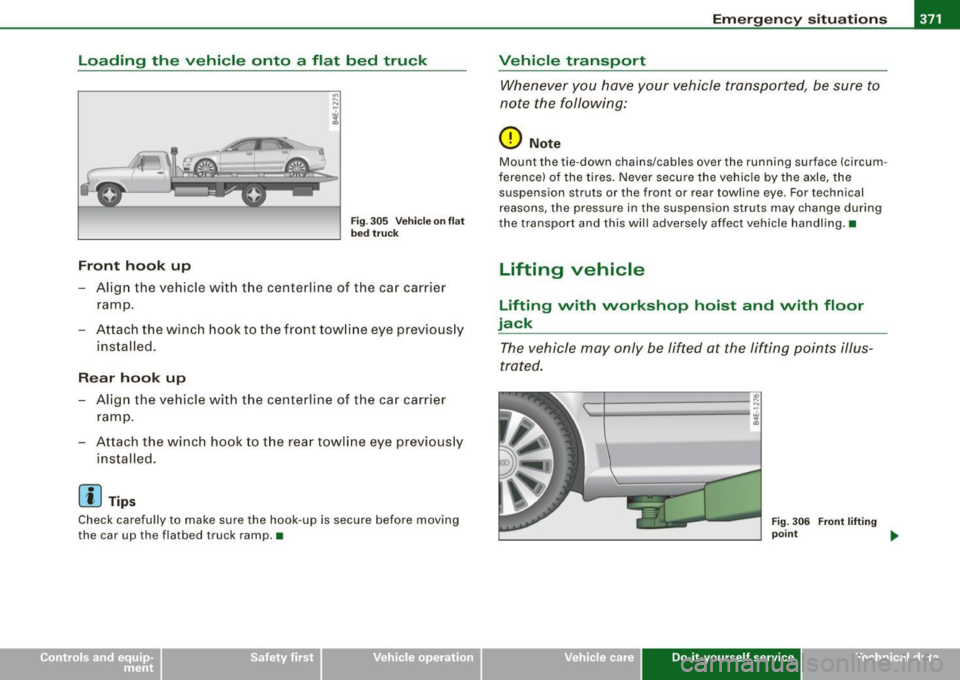
Loading the vehicle onto a flat bed truck
Front hook up
"' .... N
Fig. 305 Ve hic le on flat
bed truck
- Align the vehicle with the centerline of the car carrier
ramp .
- Attach the winch hook to the front towline eye previous ly
installed .
Rea r hook up
- Align the vehicle with the centerline of the car carrier
ramp .
- Attach the winch hook to the rear towline eye previously
installed.
[ i ] T ip s
Check carefully to make sure the hook -up is secure before moving
the car up the flatbed truck ramp. •
Vehicle transport
Whenever you have your vehicle transported, be sure to
note the following:
0 Not e
Mount the tie-down chains/cables over the running surface (circum
ference) of the tires. Never secure the vehic le by the axle, the
suspension struts or the front or rear towline eye. For technical
reasons, the pressure in the suspension struts may change during
the transport and this wil l adversely affect vehicle handling .•
Lifting vehicle
Lifting with workshop hoist and with floor
jack
The vehicle may only be lifted at the lifting points illus
trated .
--1------------- ~
'-l.=c==;;;;;;;;;;= ==-cl i
Fig. 30 6 Fron t lift ing
poi nt
~
Vehicle care Do-it-yourself service irechnical data
Page 374 of 408

-Emergency situations PV:f...__---=---=---------------
-Read and hee d W ARNI NG =:> & .
Fig. 30 7 Re ar lifting
point
Ac tiv ate t he vehicle jackin g mode if a pp licable
=:>
p age 19 1.
-Locat e lifting po in ts =:> page 371, fig. 3 06 =:> fig . 3 07 .
Ad ju st li ftin g a rms of works hop hoi st or floor jack t o
m atch v ehicle li ftin g poi nts.
In sert a r ub be r pad between the floor jack /wo rk sh op
h o ist and t he li ftin g poin ts.
The vehicle jac kin g m ode m ust be ac tiva ted so that the a utomatic
adjustment of the Adaptive Air Suspension does not make it more
d iffic ult to ra ise the vehic le w ith the ( floor jack) => page 19 1.
If you must lift your vehicle with a floor jack to work underneath , be
sure the vehicle is safely supported on stands intended for this
purpose.
Front lifting point
Th e lif ti ng po int is locat ed o n th e floo r pan re inf orc emen t abou t at
the same leve l as t he jack mounting point => page 371, fig. 306 . Do
not lift the vehicle at the vertical sill reinforcement. Rear lifting point
Th e lif tin g po int is loc ated on t he ver tical re infor ce ment o f the lo wer
s ill for t he on -boa rd jack=> fig . 3 07 .
Lifting with vehicle jack
R efer to => page
356 .
& WARNING
• To reduce the risk of serious injury and vehicle damage .
- Always lift the vehicle only at the special workshop hoist and
floor jack lift points illustrated
=> page 371 , fig . 306 and
=> fig. 307.
- Failure to lift the vehicle at these points could cause the
vehicle to tilt or fall from a lift if there is a change in vehicle
weight distribution and balance. This might happen , for
example, when heavy components such as the engine block or
transmission are removed .
• When removing heavy components like these, anchor vehicle
to hoist or add corresponding weights to maintain the center of gravity. Otherwise , the vehicle might tilt or slip off the hoist,
causing serious personal injury .
0 Note
• Be awar e of the following points be fore liftin g the vehicle :
- The vehicle should never be lifted or jacked up from under
neath the engine oil pan , the transmission housing , the front or
rear axle or the body side members . This could lead to serious
damage .
- To avoid damage to the underbody or chassis frame, a rubber
pad must be inserted between the floor jack and the lift points .
- Before driving over a workshop hoist, check that the vehicle
weight does not exceed the permissible lifting capacity of the hoist . _..
Page 375 of 408
Emergency situations -
-------------=--=----
•
-Before driving over a workshop hoist, ensure that there is
sufficient clearance between the hoist and low parts of the
vehicle. •
Do-it-yourself service
Page 376 of 408