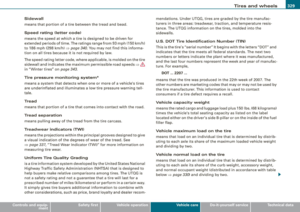
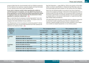
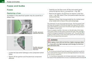
Page 9 of 408
Controls and equipment Safety first
Vehicle operation Vehicle care
About this Owner's Manual
Do-it-yourself service Technical data
Page 10 of 408
Page 11 of 408
Controls and equipment
----------- ------ ~
Page 12 of 408
Instruments and controls
Fig. 1 Some of the equipment or features shown in the general illustration may be standard equipment on your vehicle or may be optional equipment depending on your
model. Always ask your authorized Audi dealer if you have a question about your vehicle .
Page 13 of 408

Instruments and controls
General illustration
G) Power window switches .. ...... .... ... .. ....... .
0 Door handle
G) Pow er locking switches ... .... .... .... ... ....... .
© Adjuster control for outside mirrors ............. . .
© Light switch .... .... ....... ... ... .. .... .. ..... .
© Control lever for:
- Cruise control .... .... ... .... .... .... ... .... .
- Adaptive Cruise Control .. ... ....... .......... .
0 Air outlets ...... .............................. .
@ Control lever for:
- Turn signal and high beam ....... ... .... ..... .
- Lane assist .. .... ..................... ... ... .
® Multifunction steering wheel with :
- Horn
- Driver's airbag .. ...... ...... ....... ...... ... .
- Shift buttons ........... .... ... .. .... .... ... .
Button for steering wheel heating ..... .. .. .... .
@ Instrument cluster .................... .... ..... .
@ Swi tches for
- Windshield wip er/ washer ............. ... .. ... .
- Trip computer ..... ... ... .... .... ... ... ... .. .
@ Steering lock/ignition /starter switch
@ Buttons for :
- Advanced Parking System .. .... .... .... .... .. .
- Side assist ..... .. .. ... ..... .... ... .. .... ... .
- Power sunshade
@ MMI Display
Controls and equip
ment
61
53
84
69
137
139
122 73
153
224 171
119 12
80 38
129
173
156
78
Instruments and controls
@ Buttons/Indicator light for:
- Electronic Stabilization Program (ESP) 270
- PASSENGER AIR BAG OFF
- Emergency flashers . . . . . . . . . . . . . . . . . . . . . . . . . . . 73
@ Storage tray . . . . . . . . . . . . . . . . . . . . . . . . . . . . . . . . . . . 110
@ Glove compartment . . . . . . . . . . . . . . . . . . . . . . . . . . . . . 109
@ Front passenger's airbag . . . . . . . . . . . . . . . . . . . . . . . . 224
@) Shift lever for automatic transmission . . . . . . . . . . . . . 166
@ Climate controls . . . . . . . . . . . . . . . . . . . . . . . . . . . . . . . . 116
@ Rear window d efogger switch . . . . . . . . . . . . . . . . . . . . 124
@ Ashtray with cigarette lighter . . . . . . . . . . . . . . . . . . . . . 106
@ ISTART ]-~STOP ~button . . . . . . . . . . . . . . . . . . . . . . . . . 131
@ MMI Terminal
@ Storage w ith cup holder . . . . . . . . . . . . . . . . . . . . . . . . . 105
@ Electromechanical parking brake . . . . . . . . . . . . . . . . . . 134
@ Data Link Connector for On Board Diagnostics (OBD Ill 27
@ Engine hood release . . . . . . . . . . . . . . . . . . . . . . . . . . . . 308
@ Adjustable steering column . . . . . . . . . . . . . . . . . . . . . . 128
@) Memory buttons (driver's seat) . . . . . . . . . . . . . . . . . . . 94
@ Switch for
- unlocking the fuel filler door . . . . . . . . . . . . . . . . . . . 305
- unlocking the trunk lid 54
[ i ] Tips
Operation of the Multi Media Interface (MMI) is described in a sepa
rate manual. •
I • •
Page 14 of 408

Instruments and warning /indicator lights
Instruments and warning/indicator lights
Instruments
Instrument cluster and controls
The instrument cluster is your central source of informa
tion.
F ig . 2 Overview of the instrume nt cluster
CD Coolant temperature gauge ..................... .
0 Tachometer with time and date display .. ......... .
G) Warning/indicator lights .. ... .... ... ... ...... .. .
© Driver information system ..... ... .... ...... .... .
© Speedome ter with odometer ..... .... ..... ... .. .
© Fuel gauge . ..... ..... ... ... ..... ..... .... ... . .
G) Reset button for trip odometer ........... ... .... .
12
13 , 13
16
24
14
14
14
© I CH ECK] button ............. ..... .... ... ...... .
® Ins trument cluster illumination . ......... ........ .
[ i ] Tips
15
15
The illumination for the instrument cluster lights up whenever you
switch on the ignition with the vehicle headlights off. As the
daylight fades, the instrument cluster illumination likewise dims
automatically and will go out complete ly when the outside light is
very low . Th is feature is meant to remind you to switch on the head
lights when outside light conditions become poor. •
Engine coolant temperature gauge
The engine coolant gauge~ fig. 2 CD only works when the ignition
is on. To prevent damage to your engine, please note the following
important points:
Engine cold
As long as the needle remains at the left end of the gauge, the
engine still has not reached its operating temperature. Avoid high
engine speeds, heavy engine loads and heavy throttle applications.
Normal temperature
When the engine has reached its operating temperature, the needle
will move into the midd le of the gauge and remain there. If the
engine is working hard at high outside temperatures, the needle
may go furthe r to the right. This is no need to worry as long as the
J_ warning light in the instrument cluster does not illuminate.
Warning light in the instrument cluster -L
When the-•-warning light starts to flash, this can mean one of two
things: either the coo lant temperature is too high , or the coolant
level is too low~ page 31 . .,_
Page 15 of 408

If the indicator goes all the way to the right side inside the coolant
temperature gauge, then the engine coolant temperature is too
high.
Pull off the road to safe location, turn off the engine and let it
cool down.
If the warning light comes on again after you have driven
a short distance, contact a qualified workshop.
& WARNING
• Always observe the warning in :::::, page 301, "Engine compart
ment", before opening the hood and checking the engine coolant
level.
• Never open the engine hood if you see or hear steam, or if you
see engine coolant dripping from the engine compartment. You
could burn yourself. Let the engine cool off first so that you cannot
hear or see any steam or engine coolant.
0 Note
• Mounting additional lights or accessories in front of the air inlets
reduces the cooling effect of the radiator. At high outside tempera
tures or high engine load, the engine could overheat.
• The front spoiler has been designed to properly distribute the
cooling air when the vehicle is moving . If the spoiler is damaged,
this could reduce the cooling effect and the engine could then over
heat. Ask your authorized Audi dealer for assistance. •
Tachometer (engine rev counter)
The tachometer indicates the engine RPM (revolutions per
minutes).
The tachometer 0:::::, page 12, fig . 2 is the left of the two large clock
type displays.
The engine turns at a speed
1,000 times the single digit in the
display, e.g. if the needle is pointing at the "2" the engine is turning
at 2,000 RPM.
Controls and equip
ment
Instruments and warning/indicator lights
If engine RPM drops below 1,500, you should downshift to the next
lower gear. The red area at the end of the scale indicates maximum
permissible engine RPM after the break-in period. Before reaching
this area, move the selector lever to position "D (Drive)" or ease your
foot off the accelerator pedal.
0 Note
The tachometer needle should not move into the red range . If it
does, then only for a very short period of time. You could damage
your engine by driving at high RPM.
<£> For the sake of the environment
Upshifting early saves fuel and reduces engine noise .•
Digital clock with date display
Date and time of day can be set in MM/.
Fig . 3 Instrument
cluster with digital
clock
The date, time of day, and time and date format can be set in MMI.
You can find out more in the MMI manual. ..,.
I • •
Page 16 of 408

Instruments and warning /indicator lights
[ i J Tips
• The digital clock and the odometer are turned on for about 30
seconds when the driver's door is opened.
• When the ignition is turned off, the odometer reading and the
digital clock with date display can be switched on for about
30 seconds by pressing the
I CHECK) button => page 15, fig. 5. •
Speedometer with odometer
The speedometer shows you the vehicle speed, and the
odometer shows you how many miles (kilometers) you
have driven.
Fig . 4 Instrument
c luster Odometer and
reset button
The odometer and trip odometer are located inside the speedom
eter.
• USA models -Miles
• Canada models -Kilometers
You can switch the display from miles to kilometers and vice versa
via the MMI.
Lower odometer
The lower odometer shows the total number of miles (kilometers)
driven. Upper
odometer (trip odometer )
The upper odometer shows the total number of mil·es (kilometers)
driven since you last reset the odometer to zero. You can use this
odometer when you wan t to keep track of how many miles (kilome
ters) you have driven for a single trip or errand. The last d igit indi
cates 1/10 of a mile (100 meters) .
You can reset the trip odometer to zero by pressing the Reset button
(0.0).
Malfunction message
If there is a malfunction somewhere in the instrument cluster, dEF
wi ll appear in the trip odometer and will stay on. Contact your
authori zed Audi dealer to have the prob lem corrected .
Immobilizer
When you switch on the ignition, the data chip inside the key is
"read" by the immobilizer system.
If an unauthorized key is inserted into the ignition lock, the word
SAFE will come on and stay on. You will not be able to start the
vehicle=>
page 49.
[ i J Tips
• The digita l clock and the odometer are turned on for about 30
seconds when the driver's door is opened.
• When the ignition is turned off, the odometer reading and the
digital clock with date display can be switched on for about
30 seconds by pressing the
I CHECK) button=> page 15, fig. 5. •
Fuel gauge
The fuel gauge only works when the ignition is on.
The fuel tank holds about 23 .8 gallons (90 liters). When the needle
reaches the reserve mark, the=>
page 35 symbol appears in the
instrument cluster display as well as the message
Please refuel. .,_