Page 361 of 408

_______________________________________________ W_ h_ a_t _ d_ o_ l _d _o_ n_ o _ w_ ? __ fflll
•
hub. Remove all dirt from these surfaces before remounting the
whee l.•
Tires with unidirectional tread design
Tires with unidirectional tread design must be mounted
with their tread pa ttern pointed in the ri ght direction.
Using a spar e tire with a tread pattern intended for u se
in a sp ecific di rec tion
When using a spare tire with a tread pattern intended fo r use in a
specific direction, p lease note the following:
• The direction of rotation is ma rked by an arrow on the side of the
tire .
• I f the spare tire has to be insta lled in the incorrect direction, use
the spare tire only temporarily since the tire wi ll not be able to
achieve its optimum performance characteristics with regard to
aquaplaning, noise and wear.
• We recommend that you pay particular attention to this fact
during wet weather and that you adjust you r speed to match road
conditions .
• Replace the flat tire with a new one and have it installed on your
veh ic le as soon as possible to restore the handling advantages of a
un idirectional tire. •
Notes on wheel changing
Please read the information :::::, page 338, "New tires and replacing
tires and whee ls" if you are going to use a spare tire which is
di fferent from the t ires on your veh ic le.
After you change a tire :
• Check the tire pre ssure on the spare immediately after installa
tion . • Have the wheel bolt t
ighten ing torque che cked with a torque
wrench as soon as possible by your authorized Audi dealer or a qualified service station .
• With steel and alloy wheel rim s, the wheel bolts are correctly
tighte ned at a torque of 90 ft lb (120 Nm ).
• If you noti ce that the wheel bolt s are corroded and difficult to
turn while changing a ti re , they should be replaced before you che ck
the tightening torque .
• Replace the flat t ire with a new one and have it installed on your
vehicle as soon a s possible . Remount the whee l cover.
Until then , dri ve with extra care and at reduced speed s.
& WARNING
• If you are going to equip your vehi cle w ith tires or r ims which
differ from those which were factory in stalled , then be sure to read
the information :::::,
page 338, uNew tires and repla cing tires and
wheel s".
• Always mak e sure the d am aged wheel or e ven a flat t ire and
the jack and tool kit are properl y secured in the luggage compart
ment and are not loose in the pass enger compartment .
• In an a ccident or sudden maneuver they could fly forward ,
injur ing anyone in the vehicle .
• Alway s store damaged wheel , ja ck and tools securely in the
luggage comp artment . Otherwise , in an accident or sudden
m aneuv er they could fly forward , cau sing injury to pas senger s in
the veh icle .
• Do not use commercially available ti re sea lants. Othe rwise, the
ele ctri cal component s of t he tire pres sure mon itor ing system * will
no longer wo rk properly and the sen sor for the tire pre ssure moni
tor ing s ystem* w ill have to be replaced by a qualified workshop . •
Do-it -yourself service
Page 362 of 408

111'1...__F_ u_ s_ e_s _ a_n _ d_ b_ u_lb _ s _______________________________________________ _
Fuses and bulbs
Fuses
Replacing a fuse
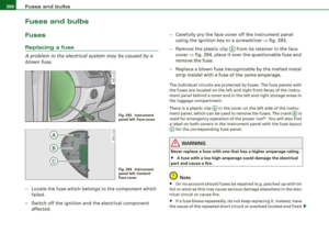
A problem in the electrical system may be caused by a
blown fuse.
Fig. 293 Instrument
panel left: Face cover
Fig . 294 Instrument
panel left: Content
Face cover
-Locate the fuse which belongs to the component which
failed.
Switch off the ignition and the electrical component
affected. -
Carefully pry the face cover off the instrument panel
using the ignition key or a screwdriver~ fig. 293.
- Remove the plastic clip@ from its retainer in the face
cover~ fig. 294, place it over the questionable fuse and
remove the fuse.
- Replace a blown fuse (recognizable by the melted metal
strip inside) with a fuse of the
same amperage.
The individual circuits are protected by fuses. The fuse panels with
the fuses are located on the left and right front faces of the instru
ment panel behind a cover and in the left and right storage areas in
the luggage compartment.
There is a plastic clip@ in the cover on the left side of the instru
ment panel, which can be used to remove the fuses. The crank © is
used for emergency operation of the power roof*. You will also find
a label on both covers in the instrument panel with the fuse layout
© for the corresponding fuse panel.
& WARNING
Never replace a fuse with one that has a higher amperage rating.
• A fuse with a too high amperage could damage the electrical
part and cause a fire.
(D Note
• On no account should fuses be repaired (e.g. patched up with tin
foil or wire) as this may cause serious damage elsewhere in the elec
trical circuit or cause fire.
• If a fuse blows repeatedly, do not keep replacing it. Instead, have
the cause of the repeated short circuit or overload located and fixed . .,_
Page 363 of 408

_________________________________________________ F_ u_ s_ e_s _ a_n _d_ b_ u _ lb_ s _ __._
[ i J Tip s
You are wel l advised to keep a supply of spare fuses in your vehic le.
Fuses with the proper ampere ratings are available at your Audi
dealer. •
Fuse Location , Instrument Panel left
F ig. 295 Fuse pan el
l ayout
Some of the equipment items listed are optiona l or only available on
certain model configurations.
No te t hat th e fo llow ing t able is acc urate a t the time o f goin g to
p re ss an d is s ubject to c hang e. In the e vent of di screpancies, the
lab el on the insi de of th e cover alwa ys ta kes prece dence .
The power windows and the power seats are protected by cir cui t
bre akers,
which automatically reset after a few seconds after the
over load -for example if a window is frozen -has been remedied .
N o. Equipm ent
1 Garage door opener (HomeLinkl 5
Parking assist system 5
3
Parking assist system 5
4
Headlight range control/light control device 10
No .
5
6
7
8
9
10
11
12
13
14
15
16
17
18
19
20
21
22
23
24
25
26
27
28
29
Equipm ent Amps
Instrument c luster
5
Steering column electronics system control 1 0
Diagnostic connector 5
Diagnostic connector/oil level sensor 5
ESP contro l unit/steering angle sensor 5
Instrument cluster 5
Audi lane assist 10
Brake light switch 5
Telephone/cell phone 10
Vacant
Access/start control module
5
RSE system 10
Adaptive Cruise Control 5
Heate d washer jets 5
Vacant
Tire pressure monitoring system*
5
Vacant
Brake light switch
5
Ce ll phone preparation 5
Horn 1 5
Windshield wiper system 40
Vacant
E lectronic Stabilization Program (ESP)
25
Vacant
Switch illumination
1
Vehicle care Do-it-yourself service irechnical data
Page 364 of 408

11111...__F_ u_ s_ e_s _ a_n _ d_ b_ u_lb _ s _______________________________________________ _
No. Equipm ent
30 Vacant
31 On board power supply, light control (right
headlight)
32 Vacant
33 Left rear footwell heater
35 Vacant
36
37
38
39
40 Audi side assis
t
Cooler
On board po wer supply, light cont rol (left head
light)
Door contro l unit, driver 's side
Power ste ering column adjus tment
41 Door contro l unit, rear left
42 Access/start control module
43 Adaptive Light, left
--44 Adaptive Light, right
Amps
30
25
5
15
30
7.5
25
7.5
25
10
10 •
Fuse Location , Instrument Panel right
Fig . 296 F use pa nel
l ay ou t
Some of the equipment items listed are optional or only available on
certain model configura tions.
Note that the following t able is accurate at th e tim e of go ing to
pr es s an d is subje ct to change . In the eve nt of di screp ancies, th e
l a bel on the in side of the cov er a lways ta k es prece dence .
The power window regulators and the power seats are protected by
cir cuit br eak ers, which automatically reset after a few seconds after
the over load - for example if a window is frozen - has been reme
died .
No. Equipm ent
1 Parking brake
2
3
5
6
7
Air conditioning
Shi ft gate
Engine control
Oxygen sensor before the three-way
catalytic converter
Oxygen sensor behind the three-way
catalytic converter
Amp s
5
10
5
15
15
15
-
Page 365 of 408

_________________________________________________ F_ u_ s_ e_s _ a_n _d_ b_ u _ lb_ s _ __.11111
No. II Equipment
8 Engine control, auxiliary water pump
9
10
11
12
13
Climate control front /rear, dash panel buttons
Suspension leve l control system
(Adaptive Air Suspension)
Light and rain sensor
Display-/control unit
Roof electronics control unit
CD/DVD drive
15 Energy managemen t
16 Vacant
17 Radiator fan electronics
18 Airbag front passenger recognition
(weight sensor)
19 Vacant
20 Heated/ventilated seats
21 Engine control module
22 Vacant
23 Parking brake (switch)
24 Vehicle electrical system
25
26
27
Automatic transmission Air conditioning water valves water pump, rear climate control
Sunroof
28 Engine control module
29 Fuel injectors
30 Ignition coils Amps
10
5
10
5
5
10
5
5
5
5
5
5
5
10
15
10
20
5
15
30 No. Equipment
31 Fuel pump, right/fuel pump electronics
32 Automatic transmission
33 Right rear footwell heater
34 Heated/ventilated seats, rear
35 Heated/ventilated seats, front
36 Cigarette l ighter, front
37 Cigarette lighte r, rear/socket, rear
38 Auxiliary cooler fan
39 Door control unit, front right
40 Brake booster
41 Door control unit, rear right
42 Vacant
43 Headlight washer system
44 Air conditioning heater fan Amps
20/40
5
25
20
20
20
20/25 20
7.5
15
7.5
30
30
•
Fuse Location , Luggage Compa rtment left
0
Fig . 297 Fuse panel
layout _.
Vehicle care Do-it-yourself service irechnical data
Page 366 of 408

111'1...__F_ u_ s_ e_s _ a_n _ d_ b_ u_lb _ s _______________________________________________ _
No. Equipment Amps
1 Vacant
2 Vacant
3 Vacant
4 Vacant
5 Digital sound system control module 30
6 Navigation 5
7
TV Tuner 10
8 Rear -view camera 5
9 Communications box 5
10 Subwoofer in rear window shelf (BOSE)/ 15/30 Amplifier (Bang & Olufsen)
--
1 1 Socket 20
12 Vacant
Fuse Location, Luggage Compartment right
Fig. 298 Fuse panel
layout
I
•
No. Equipment Amps
1 Vacant
2 Fuel pump, left 20
3 Vacant
4 Vacant
5 Central control module for comfort system 20 (left light)
-
6 Central control module for comfort system 10 (right light)
Central control module for comfort system
7 (door closing) 20
8 Electronic parking brake control module, left 30
9 Electronic parking brake control module, right 30
10 Vacant
11 Vacant
12 Vacant
Bulbs
Replacing light bulbs
For your safety, we recommend that you have your autho
rized Audi dealer replace burned out bulbs for you.
It is becoming increasingly more and more difficult to replace
vehicle light bulbs since in many cases, other parts of the car must
first be removed before you are able to get to the bulb. This applies
especially to the light bulbs in the front of your car which you can
only reach through the engine compartment.
•
Sheet metal and bulb holders can have sharp edges that can cause
serious cuts, and parts must be correctly taken apart and then prop-.,
Page 367 of 408

_________________________________________________ F_ u_ s_ e_s _ a_n _ d_ b_ u_lb _ s __ llll
•
erl y put back to g eth er to help pr eve nt brea kage of parts and long
te rm dam age fro m water that can enter h ous ing s th at h ave not
been properly resealed.
F or y our safety , we reco mmend that you have your autho rized A udi
dea ler rep lace any b ulbs for you, s ince you r deale r has the proper
tools, the correct bu lbs and the expertise.
Gas discharge lamps (Xenon lights):
D ue to the hi gh e lectrical voltage, have the bu lbs replaced by a qual
ified techn ic ian. Headlights wi th Xenon light can be ide ntifie d by the
h igh voltage s tic ke r.
& WARNING
Contact with high-voltage components of the ele ctri cal system
and improper replacement of gas discharge (Xenon) headlight
bulbs can cause ser ious personal injury and death .
• Xenon bulbs are pressurized and can explode when being
changed .
• Changing Xenon lamps requires the special training, instruc
tions and equipment .
• Only an authorized Audi dealer or other qualified workshop
should change the bulbs in gas discharge lamps .
& WARNING
There are parts with sharp edges on the openings and on the bulb
holders that can cause serious cuts.
• If you are uncertain about what to do, have the work performed
by an authorized Audi dealer or other qualified workshop. Serious
personal injury may result from improperly performed work.
[ i ] Tips
• I f you must replace the light bulbs yourse lf , always remember
tha t the e ngi ne compartmen t of an y ve hic le i s a hazardous area to work in. Always read and heed al
l WARNINGS=>
page 301, " E ngine
c om partm ent" =>& .
• I t is best to ask your authorized Audi dealer whenever you need
to ch ang e a bul b.•
Do-it -yourself service
Page 368 of 408

1111.___E_ m _ e _r-==g :...e_ n_ c...:y _ s_ i_t _u _a _t_ i_o _n_ s _______________________________________________ _
Emergency situations
General
This section is intended for trained emergency crews and personnel
who have the necessary tools and equipment to perform these
operations. •
Starting by pushing or towing
0 Note
Your ve hicle is equipped wit h an auto matic trans mis sion. C onse
quent ly, the engine cannot be started by pushing or tow ing .•
Starting with jumper cables
If n ece ssar y, the eng in e c an b e star ted by conne cting it to
the battery of anoth er veh icle .
If th e engine shou ld fai l to start because of a discharged or weak
ba ttery , the bat te ry can be connected t o the ba ttery of
another
vehic le, using a pair of jumper cables to start the engine.
Jumper cables
Use
only jumper cabl es o f sufficient ly la rgecross section to carry the
st arte r current safe ly . R efer to th e manu fac tur er's speci fica tions.
Us e on ly jumper cables w ith
i n sulated te rminal clamps w hic h are
d istinct ly marked:
plus (+l cable in m ost cas es c olore d red
minus (-l cable in most cases co lored black .
& WARNING
Batteries contain electricity , acid , and gas . Any of these can cause
very serious or fatal injury. Follow the instructions below for safe
handling of your vehicle 's battery .
• Always shield your eyes and avoid leaning over the battery
whenever possible .
• A discharged battery can freeze at temperatures just below
32 °F (0 °C l. Before connecting a jumper cable , you must thaw the
frozen battery completely , otherwise it could explode.
• Do not allow battery a cid to contact eyes or skin . Flush any
contacted area with water immediately.
• Improper use of a booster battery to start a vehicle may cause
an explosion.
• Vehicle batteries generate e xplosive gases . Keep sparks, flame
and lighted cigarettes away from batteries.
• Do not try to jump start any vehicle with a low ac id level in the
battery.
• The voltage of the booster battery must also have a 12-Volt
rating . The capacity (Ahl of the booster battery should not be
lower than that of the discharged battery . Use of batteries of
different voltage or substantially different "Ah " rating may cause
an e xplosion and personal injury .
• Never charge a frozen battery. Gas trapped in the ice may cause
an explosion .
• Never charge or use a battery that has been frozen . The battery
case may have be weakened.
• Use of batteries of different voltage or substantially different
capacity (Ah ) rating may cause an explosion and injury . The
capacity (Ahl of the booster battery should not be lower than that
of the discharged battery . .,_