Page 25 of 391

PASSENGER COMPARTMENT CONNECTION UNIT
Fault finding - System operation
87B
87B-25
PASSENGER COMPARTMENT CONNECTION UNIT
Fault finding - System operation
87B
87B-25V9 MR-372-J84-87B000$086.mif
UCH
Vdiag No.: 44, 48,
4C, 4D, 4F, 50
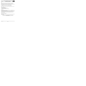
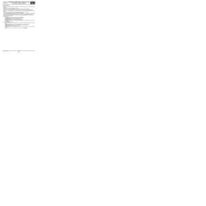
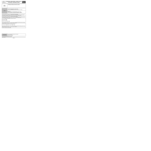
1.2.2 Unlocking/locking the steering column:
1Steering column lock
2multiplex line
3Supply
4Sensor Line
5Safety line
a/ Unlocking the steering column lock
Following authentication of the Renault card:
1/ The UCH sends a code to the electric steering column lock with an unlocking request via the multiplex network
(ET119 UCH request to steering column lock).
2/ If the electric steering column lock recognises the code, it unlocks and sends its unlocked status to the UCH
(ET073 Steering column lock sensor signal).
3/ When the UCH receives the "Steering column unlocking completed" signal, it orders the Protection and Switching
Unit to activate the + after ignition relay and the procedure continues.
The physical status of the column lock can be displayed by status ET072 Steering column lock and its
programming can be displayed by status ET071 Steering column lock blank.
The steering column lock remains locked if:
–There is excessive mechanical load on the steering column (e.g.: wheel jammed against a kerb),
–the battery voltage is too low,
–the power demanded by the column lock is too high (thermal protection of the column lock electric motor). Note:
After ignition feed can only be established if the steering column unlocking procedure is performed
correctly.
Page 26 of 391

PASSENGER COMPARTMENT CONNECTION UNIT
Fault finding - System operation
87B
87B-26
PASSENGER COMPARTMENT CONNECTION UNIT
Fault finding - System operation
87B
87B-26V9 MR-372-J84-87B000$086.mif
UCH
Vdiag No.: 44, 48,
4C, 4D, 4F, 50
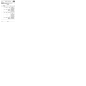
b/ Locking the steering column:
The steering column is locked with the engine off, after the Renault card is removed from the card reader. This
locking operation requires:
–a valid 0 mph (0 km/h) speed signal,
–a correctly functioning airbag and no impact detected,
–a deactivated + after ignition connection.
When the engine has not been started but the after ignition feed is active (e.g. forced after ignition feed), certain
conditions in which there is a drop in the after ignition feed do not cause the steering column to lock ("steering
column not locked" message).
Steering column lock fails if:
1/ Normal non-locking scenarios:
–the card is present in the card reader,
–more than 20 minutes has elapsed with the card in the reader and the engine off,
–the vehicle speed is not zero,
–power is demanded by the steering column lock too frequently.
With regard to vehicles fitted with UCH computer Vdiag 4F or above:
–the Renault card is removed from the card reader when the vehicle is in forced + after ignition feed,
–3 minutes have elapsed following a starting failure due to an engaged gear,
–the Renault card is removed from the card reader following a starting failure due to an engaged gear,
–a front door is open following a starting failure due to an engaged gear and the card is not in the reader.
To lock the steering column, start and stop the engine again.
2/ Abnormal non-locking scenarios:
–the airbag unit is faulty or locked,
–the airbag unit is disconnected,
–the airbag has been triggered,
–the speed signal is not available.
In the event that a steering column does not lock, the driver is informed via the message Steering column not locked.
1.2.3 Locking the injection computer:
When the + after ignition feed has been established, the UCH and the injection computer compare their codes via
the multiplex network. If the codes are identical, the vehicle immobiliser is deactivated (ET046 Immobiliser).
If there is a failure, the immobiliser remains active.
Reactivating protection: the immobiliser is reactivated when the engine stops.
Page 27 of 391

PASSENGER COMPARTMENT CONNECTION UNIT
Fault finding - System operation
87B
87B-27
PASSENGER COMPARTMENT CONNECTION UNIT
Fault finding - System operation
87B
87B-27V9 MR-372-J84-87B000$086.mif
UCH
Vdiag No.: 44, 48,
4C, 4D, 4F, 50
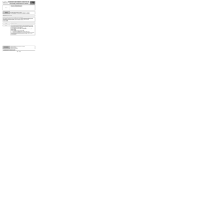
1.2.4 Renault card check by the UCH:
a/ Card check:
When the engine is running, the UCH checks for the presence of the Renault card in the passenger compartment (if
vehicle is hands-free) or in the card-reader when a door is opened then closed. If the Renault card is not detected, a
message on the instrument panel and a buzzer warn the driver.
Command AC036 Internal aerial test is used to check the area covered by the starting aerials inside the passenger
compartment (hands-free vehicles). The card reader flashes when the card is detected.
This command allows a hands-free card to be recognised even if it does not belong to the vehicle.
b/ Low battery warning:
If the Renault card battery is faulty or flat, the change card battery message is displayed on the instrument panel
when the vehicle is started, if there have been 5 attempts to authenticate the Renault card since the battery fault.
c/ Storing information on the card:
A device allowing information relating to the vehicle to be read from the card is available.
Information available: – VIN (Vehicle Identification Number).
–Mileage.
–Fuel level.
–Mileage before oil change.
–Tyre pressure (if vehicle fitted with SSPP).
–Status of OBD warning light.
–Oil level.
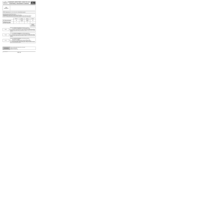
2.5 Immobiliser warning light programs
Immobiliser warning light Vehicle protection status
Ignition
offWarning light flashes slowlyVehicle protected (immobiliser active or fault with
steering lock)
Warning light not lit New vehicle or blank UCH storage mode
Ignition
onWarning light flashes slowly Renault card not recognised
Warning light continuously lit Injection authentication fault
Warning light not lit Vehicle unprotected (immobiliser inactive)
Page 28 of 391

PASSENGER COMPARTMENT CONNECTION UNIT
Fault finding - System operation
87B
87B-28
PASSENGER COMPARTMENT CONNECTION UNIT
Fault finding - System operation
87B
87B-28V9 MR-372-J84-87B000$086.mif
UCH
Vdiag No.: 44, 48,
4C, 4D, 4F, 50
1.3 SUB-FUNCTION: STARTING
The UCH manages the control section of the starting sub-function. For this function to operate normally, the
protection function must proceed correctly (immobiliser inactive ET046 Immobiliser).
In order to control the starter motor, the UCH requires the following status and parameter information to check that
the starting conditions have been met:
–Start button ET070 Start button.
–Clutch pedal position ET048 Clutch pedal position.
–Brake pedal position ET047 Brake pedal position.
–Automatic gearbox selector lever position ET108 Automatic gearbox selector lever position.
–Position of the manual gearbox selector lever (see 87G, Engine compartment connection unit, Conformity
check).
If the starting conditions are met, the request for the Protection and Switching Unit to activate the starter motor can
be viewed using status ET110 UCH request to injection or Protection and Switching Unit.
1.4 Main COMPONENTS of the ACCESS/SAFETY function
1.4.1 Main components of the ACCESS sub-function:
–Renault card,
–UCH,
–optical presence sensors located in the door handles,
–access aerials integrated in the door handles and the tailgate,
–the locking switches incorporated in the door handles,
–the boot-only opening/locking switch built into the boot badge,
–opening element locking motors.
1.4.1.1 The Renault card:
The Renault card has three buttons which allow:
–locking of the vehicle,
–unlocking of the vehicle,
–the boot to be locked/unlocked.
The Renault hands-free card allows hands-free operation if it is located in the access and starting zones.
The Renault card is powered by a 3 V battery. This battery is required for operation in hands-free mode or remote
control mode (card button presses).
If the battery is old or in an area of frequency interference, the emergency insert located in the Renault card allows
the driver's door to be unlocked.
Page 29 of 391

PASSENGER COMPARTMENT CONNECTION UNIT
Fault finding - System operation
87B
87B-29
PASSENGER COMPARTMENT CONNECTION UNIT
Fault finding - System operation
87B
87B-29V9 MR-372-J84-87B000$086.mif
UCH
Vdiag No.: 44, 48,
4C, 4D, 4F, 50
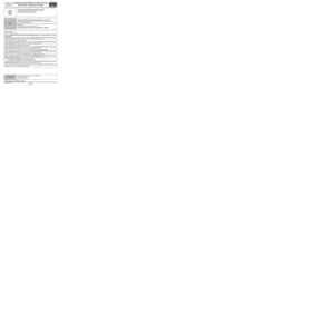
1.4.1.2 The UCH:
1.4.1.3 The optical presence sensors built into the door handles (hands-free vehicles):
The optical presence sensors inform the UCH of the hands-free unlocking request for the entire vehicle when the
infrared beam is cut in one of the handles (by a hand).
This presence detection starts the hands-free access procedure.
To limit battery use, the optical sensors are powered at 12 V only for 72 hours after the last change of vehicle
locked-unlocked status. After this period, the handle must be pulled to operate a switch* which "wakes up" the UCH
to resupply the optical sensors. In this case, pull the handle a second time to open the door once the card has been
authenticated.
The switch signal* is parallel to the optical sensor signal: activation of the optical sensor or the switch* earths the
signal going to the UCH. Although it is a switch*, the signal is not constant when pulling and holding the handle.
switch*: Switch.a) In hands-free mode, the UCH receives the unlocking request through the optical sensors, and the
locking request through the locking switches.
b) The UCH manages the exchanges with the Renault card.
In hands-free mode:
The UCH interrogates and authenticates the Renault card via the access aerials located in the door
handles and the tailgate, at a frequency of 125 KHz.
After authentication from the UCH, the Renault card responds directly to it at 433 MHz.
Outside hands-free mode:
The UCH receives the access requests coming from card presses at 433 MHz (315 MHz in Japan).
The 433 MHz reception aerial is incorporated in the UCH (except Scénic II fitted with the SSPP function).
The signals are encrypted.
c) The UCH activates the locking motors.
If the exchanges between the Renault card and the UCH are correct, the UCH activates the locking
motors.
Page 30 of 391
PASSENGER COMPARTMENT CONNECTION UNIT
Fault finding - System operation
87B
87B-30
PASSENGER COMPARTMENT CONNECTION UNIT
Fault finding - System operation
87B
87B-30V9 MR-372-J84-87B000$086.mif
UCH
Vdiag No.: 44, 48,
4C, 4D, 4F, 50
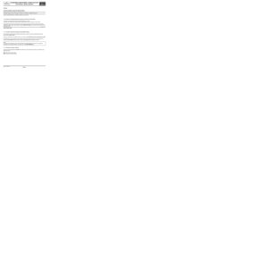
The handle groups are shown in the diagram below:
Communal sensor supply
Note:
The tailgate is not fitted with an infrared optical sensor. The boot and rear screen opening switches notify the UCH
of a request to open the boot or rear screen.
Optical
sensor
+
SwitchDriver's side
Passenger side
Optical
sensor
+
Switch
Optical
sensor
+
SwitchOptical
sensor
+
Switch
Boot unlocking
Page 31 of 391

PASSENGER COMPARTMENT CONNECTION UNIT
Fault finding - System operation
87B
87B-31
PASSENGER COMPARTMENT CONNECTION UNIT
Fault finding - System operation
87B
87B-31V9 MR-372-J84-87B000$086.mif
UCH
Vdiag No.: 44, 48,
4C, 4D, 4F, 50
1.4.1.4 The access aerials built into the door handles and tailgate (hands-free vehicles):
The access aerials are built into the door handles and the tailgate. Only the boot aerial is removable.
The UCH activates these aerials in the following order:
–the side on which the handle has been pulled,
–if the card has not been detected, the UCH activates the aerials on the opposite side,
–if the card is still not detected, the UCH interrogates the rear aerial.
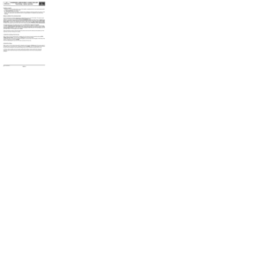
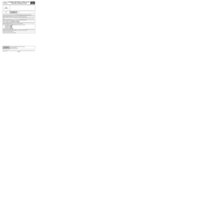
The access aerial groups are shown in the diagram below:
Note:
5-door versions manufactured before January 2007 and 3-door versions differ in that they have different handle
access aerials.
Note:
5-door versions manufactured after January 2007 have no access aerials in the rear door handles and have access
aerials in the front door handles identical to those in 3-door versions.
Driver's side
Passenger side
Tailgate
Page 32 of 391
PASSENGER COMPARTMENT CONNECTION UNIT
Fault finding - System operation
87B
87B-32
PASSENGER COMPARTMENT CONNECTION UNIT
Fault finding - System operation
87B
87B-32V9 MR-372-J84-87B000$086.mif
UCH
Vdiag No.: 44, 48,
4C, 4D, 4F, 50
1.4.1.5 The locking switches built into the door handles and the tailgate badge (hands-free vehicles):
These switches are used to lock the opening elements. They are not removable, except for the tailgate switch which
is separate from the badge. When a switch is pressed, a UCH track is connected to earth, informing it of a vehicle
locking request. The access aerials are then activated.
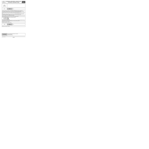
The grouping of these switches is shown in the diagram below:
Driver's side Passenger side
Locking switch Locking switch
Boot lid switch