Page 169 of 391

PASSENGER COMPARTMENT CONNECTION UNIT
Fault finding - Interpretation of statuses
87B
87B -169
PASSENGER COMPARTMENT CONNECTION UNIT
Fault finding - Interpretation of statuses
87B
87B -169V9 MR-372-J84-87B000$473.mif
UCH
Vdiag No.: 44, 48,
4C, 4D, 4F, 50
ET047
CONTINUED 3
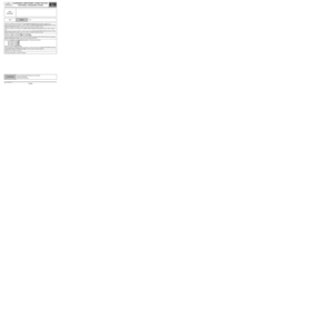
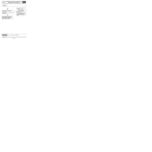
ET047 Undetermined with the pedal depressed.
Check the condition and connection of the brake pedal switch connector.
If the connector is faulty and if there is a repair method (see Technical Note 6015A, Repairing electrical wiring,
Wiring: Precautions for repair), repair the connector; otherwise, replace the wiring.
With the brake pedal switch disconnected:
Check for + 12 V on component 160 on connection SP17.
If not correct:
–Check the condition and connection of fuse 1H in the passenger compartment relay and fuse box.
–Check the condition and the connection of the passenger compartment fuse and relay box connector. If the
connector is faulty and if there is a repair method (see Technical Note 6015A, Repairing electrical wiring,
Wiring: Precautions for repair), repair the connector; otherwise, replace the wiring.
–Check the insulation and continuity of connection SP17 between components 160 and 260. If the connection
is faulty and there is a repair procedure (see Technical Note 6015A, Electrical wiring repair, Wiring:
Precautions for repair), repair the wiring, otherwise replace it.
If it is still faulty, contact Techline.
With the brake pedal switch disconnected:
Check the continuity of the following connections:
●Connection code 65A,
●Connection code SP17 of component 160 (brake pedal switch piston free).
Only replace the brake pedal switch if it is not correct.
Check the condition and connection of the UCH connector PE2.
If the connector is faulty and if there is a repair method (see Technical Note 6015A, Repairing electrical wiring,
Wiring: Precautions for repair), repair the connector; otherwise, replace the wiring.
With the UCH and brake pedal switch disconnected:
Check the insulation and continuity of the following connection:
●Connection code 65A between components 645 and 160.
If the connection is faulty and there is a repair procedure (see Technical Note 6015A, Electrical wiring repair,
Wiring: Precautions for repair), repair the wiring, otherwise replace it.
The line is shared with the ABS computer or the ESP relay (depending on equipment) and the brake lights. In the
event of faulty insulation, it is therefore necessary, using a wiring diagram, to check the connections between the
brake pedal switch connector and these components.
AFTER REPAIRCarry out another fault finding check on the system.
Clear the stored faults.
Deal with any other faults.
Page 170 of 391

PASSENGER COMPARTMENT CONNECTION UNIT
Fault finding - Interpretation of statuses
87B
87B -170
PASSENGER COMPARTMENT CONNECTION UNIT
Fault finding - Interpretation of statuses
87B
87B -170V9 MR-372-J84-87B000$473.mif
UCH
Vdiag No.: 44, 48,
4C, 4D, 4F, 50
ET048
CLUTCH PEDAL POSITION
NOTESThere must be no present or stored faults.
Special note:
Switch on forced after ignition.
Use Wiring Diagrams Technical Note for MEGANE II or SCENIC II.
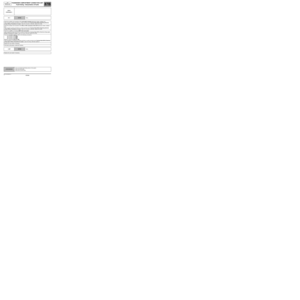
ET048 Released with the pedal depressed.
Check the connection and condition of the connector for the clutch pedal switch.
If the connector is faulty and if there is a repair method (see Technical Note 6015A, Repairing electrical wiring,
Wiring: Precautions for repair), repair the connector; otherwise, replace the wiring.
Remove the clutch pedal switch and check for earth on connection MAN of component 675.
If the connector is faulty and if there is a repair method (see Technical Note 6015A, Repairing electrical wiring,
Wiring: Precautions for repair), repair the connector; otherwise, replace the wiring.
Check the continuity of the following connections:
●Connection code 26X,
●Connection code MAN of component 675 (Brake pedal switch in pedal depressed position).
Only replace the clutch pedal switch if it is not correct.
Check the condition and connection of connector PE1 on the UCH.
If the connector is faulty and if there is a repair procedure (see Technical Note 6015A, Repairing electrical
wiring, Wiring: Precautions for repair), repair the connector; otherwise, replace the wiring.
Check the insulation and continuity of the following connection:
●Connection code 26X between components 645 and 675.
If the connection is faulty and there is a repair procedure (see Technical Note 6015A, Electrical wiring repair,
Wiring: Precautions for repair), repair the wiring, otherwise replace it.
If the fault is still present, contact the Techline.
AFTER REPAIRCarry out another fault finding check on the system.
Clear the stored faults.
Deal with any other faults.
UCH_V44_ET048/UCH_V48_ET048/ UCH_V4C_ET048/
UCH_V4D_ET048 /UCH_V4F_ET048/UCH_V50_ET048
Page 171 of 391

PASSENGER COMPARTMENT CONNECTION UNIT
Fault finding - Interpretation of statuses
87B
87B -171
PASSENGER COMPARTMENT CONNECTION UNIT
Fault finding - Interpretation of statuses
87B
87B -171V9 MR-372-J84-87B000$473.mif
UCH
Vdiag No.: 44, 48,
4C, 4D, 4F, 50
ET048
CONTINUED
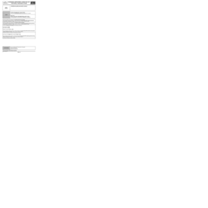
ET048 Depressed without depressing the pedal.
Check the condition and connection of the clutch pedal switch connector.
If the connector is faulty and if there is a repair procedure (see Technical Note 6015A, Repairing electrical
wiring, Wiring: Precautions for repair), repair the connector; otherwise, replace the wiring.
Remove the clutch pedal switch and check the insulation between the following connections:
●Connection code 26X,
●Connection code MAN of component 675 (Brake pedal switch in pedal released position).
Only replace the clutch pedal switch if it is not correct.
Check the condition and connection of connector PE1 on the UCH
If the connector is faulty and if there is a repair procedure (see Technical Note 6015A, Repairing electrical
wiring, Wiring: Precautions for repair), repair the connector; otherwise, replace the wiring.
Check the insulation and continuity of the following connection:
●Connection code 26X. Between components 645 and 675.
If the connection is faulty and there is a repair procedure (see Technical Note 6015A, Electrical wiring repair,
Wiring: Precautions for repair), repair the wiring, otherwise replace it.
If the fault is still present, contact the Techline.
AFTER REPAIRCarry out another fault finding check on the system.
Clear the stored faults.
Deal with any other faults.
Page 172 of 391

PASSENGER COMPARTMENT CONNECTION UNIT
Fault finding - Interpretation of statuses
87B
87B -172
PASSENGER COMPARTMENT CONNECTION UNIT
Fault finding - Interpretation of statuses
87B
87B -172V9 MR-372-J84-87B000$473.mif
UCH
Vdiag No.: 44, 48,
4C, 4D, 4F, 50
ET050
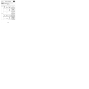
TAILGATE/BOOT
NOTESThere must be no present or stored faults.
Use Wiring Diagrams Technical Note for MEGANE II or SCENIC II.
Check the condition and connection of the PE1 connector of the UCH (tabs bent, broken, oxidised etc.).
If the connector is faulty and if there is a repair procedure (see Technical Note 6015A, Repairing electrical
wiring, Wiring: Precautions for repair), repair the connector; otherwise, replace the wiring.
Check the condition and connection of the boot lock connector (bent, broken, oxidised tabs, etc.).
If the connector is faulty and if there is a repair procedure (see Technical Note 6015A, Repairing electrical
wiring, Wiring: Precautions for repair), repair the connector; otherwise, replace the wiring.
Check the insulation and continuity of the following connection:
●Connection code 87T between components 645 and 1322.
If the connection is faulty and there is a repair procedure (see Technical Note 6015A, Electrical wiring repair,
wiring: precautions for repair), repair the wiring, otherwise replace it.
Check:
The insulation of component 1332 on connections 87T and MZ (tailgate lock contact in rest position).
The continuity of component 1332 on connections 87T and MZ (tailgate lock contact engaged).
Replace the lock if it is not correct.
If the fault is still present, contact the Techline.
AFTER REPAIRCarry out another fault finding check on the system.
Clear the stored faults.
Deal with any other faults.
UCH_V44_ET050/UCH_V48_ET050/ UCH_V4C_ET050/
UCH_V4D_ET050 /UCH_V4F_ET050/UCH_V50_ET050
Page 173 of 391

PASSENGER COMPARTMENT CONNECTION UNIT
Fault finding - Interpretation of statuses
87B
87B -173
PASSENGER COMPARTMENT CONNECTION UNIT
Fault finding - Interpretation of statuses
87B
87B -173V9 MR-372-J84-87B000$473.mif
UCH
Vdiag No.: 44, 48,
4C, 4D, 4F, 50
ET051
REAR LEFT-HAND DOOR
NOTESThere must be no present or stored faults.
Use Wiring Diagrams Technical Note for MEGANE II or SCENIC II.
Check the condition and connection of the PE1 connector of the UCH (tabs bent, broken, oxidised etc.).
If the connector is faulty and if there is a repair method (see Technical Note 6015A, Repairing electrical wiring,
Wiring: Precautions for repair), repair the connector; otherwise, replace the wiring.
Check the condition and connection of the rear left-hand door lock connector (bent, broken, oxidised tabs, etc.).
If the connector is faulty and if there is a repair method (see Technical Note 6015A, Repairing electrical wiring,
Wiring: Precautions for repair), repair the connector; otherwise, replace the wiring.
Check the insulation and continuity of the following connection:
●Connection code 87A between components 645 and 139.
If the connection is faulty and there is a repair procedure (see Technical Note 6015A, Electrical wiring repair,
wiring: precautions for repair), repair the wiring, otherwise replace it.
Check:
The insulation of component 139 on connections 87A and MZ (door open).
The continuity of component 139 on connections 87A and MZ (door closed).
Replace the lock if it is not correct.
If the fault is still present, contact the Techline.
AFTER REPAIRCarry out another fault finding check on the system.
Clear the stored faults.
Deal with any other faults.
UCH_V44_ET051/UCH_V48_ET051/ UCH_V4C_ET051/
UCH_V4D_ET051 /UCH_V4F_ET051/UCH_V50_ET051
Page 174 of 391

PASSENGER COMPARTMENT CONNECTION UNIT
Fault finding - Interpretation of statuses
87B
87B -174
PASSENGER COMPARTMENT CONNECTION UNIT
Fault finding - Interpretation of statuses
87B
87B -174V9 MR-372-J84-87B000$473.mif
UCH
Vdiag No.: 44, 48,
4C, 4D, 4F, 50
ET052
REAR RIGHT-HAND DOOR
NOTESThere must be no present or stored faults.
Use Wiring Diagrams Technical Note for MEGANE II or SCENIC II.
Check the condition and connection of the PE1 connector of the UCH (tabs bent, broken, oxidised etc.).
If the connector is faulty and if there is a repair procedure (see Technical Note 6015A, Repairing electrical
wiring, Wiring: Precautions for repair), repair the connector; otherwise, replace the wiring.
Check the condition and connection of the rear right-hand door lock connector (bent, broken, oxidised tabs, etc.).
If the connector is faulty and if there is a repair procedure (see Technical Note 6015A, Repairing electrical
wiring, Wiring: Precautions for repair), repair the connector; otherwise, replace the wiring.
Check the insulation and continuity of the following connection:
●Connection code 87B between components 645 and 138.
If the connector is faulty and if there is a repair procedure (see Technical Note 6015A, Repairing electrical
wiring, Wiring: Precautions for repair), repair the connector; otherwise, replace the wiring.
Check:
The insulation of component 138 on connections 87B and MAQ (door open).
The continuity of component 138 on connections 87B and MAQ (door closed).
Replace the lock if it is not correct.
If the fault is still present, contact the Techline.
AFTER REPAIRCarry out another fault finding check on the system.
Clear the stored faults.
Deal with any other faults.
UCH_V44_ET052/UCH_V48_ET052/ UCH_V4C_ET052/
UCH_V4D_ET052 /UCH_V4F_ET052/UCH_V50_ET052
Page 175 of 391

PASSENGER COMPARTMENT CONNECTION UNIT
Fault finding - Interpretation of statuses
87B
87B -175
PASSENGER COMPARTMENT CONNECTION UNIT
Fault finding - Interpretation of statuses
87B
87B -175V9 MR-372-J84-87B000$473.mif
UCH
Vdiag No.: 44, 48,
4C, 4D, 4F, 50
ET053
DRIVER'S DOOR
NOTESThere must be no present or stored faults.
Use Wiring Diagrams Technical Note for MEGANE II or SCENIC II.
Check the condition and connection of the PE1 connector of the UCH (tabs bent, broken, oxidised etc.).
If the connector is faulty and if there is a repair procedure (see Technical Note 6015A, Repairing electrical
wiring, Wiring: Precautions for repair), repair the connector; otherwise, replace the wiring.
Check the condition and connection of the driver's side door lock connector (bent, broken, oxidised tabs, etc.).
If the connector is faulty and if there is a repair procedure (see Technical Note 6015A, Repairing electrical
wiring, Wiring: Precautions for repair), repair the connector; otherwise, replace the wiring.
Check the insulation and continuity of the following connection:
●Connection code 87H between components 645 and 140.
If the connector is faulty and if there is a repair procedure (see Technical Note 6015A, Repairing electrical
wiring, Wiring: Precautions for repair), repair the connector; otherwise, replace the wiring.
Check:
The insulation of component 138 on connections 87B and MAQ (door open).
The continuity of component 138 on connections 87B and MAQ (door closed).
Replace the lock if it is not correct.
If the fault is still present, contact the Techline.
AFTER REPAIRCarry out another fault finding check on the system.
Clear the stored faults.
Deal with any other faults.
UCH_V44_ET053/UCH_V48_ET053/ UCH_V4C_ET053/
UCH_V4D_ET053 /UCH_V4F_ET053/UCH_V50_ET053
Page 176 of 391

PASSENGER COMPARTMENT CONNECTION UNIT
Fault finding - Interpretation of statuses87B
87B - 176V9 MR-372-J84-87B000$516.mif
UCH
Vdiag No.: 44, 48,
4C, 4D, 4F, 50PASSENGER COMPARTMENT CONNECTION UNIT
Fault finding - Interpretation of statuses
ET054
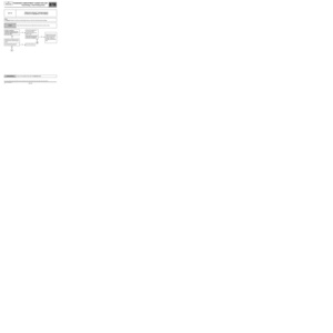
OPTICAL SENSORS SUPPLIED
NOTESAfter 72 hours without an attempt to open the vehicle, the UCH cuts out the
optical sensors' power supply.
To restore the power supply to the optical sensors, pull the handle to wake-up
the UCH.
Use Wiring Diagrams Technical Note for MEGANE II or SCENIC II.
The vehicle has been immobilised for fewer than 72 hours:
Check that the UCH is in hands-free configuration by means of LC001 Hands-free function configuration reading.
If everything is correct, contact the Techline.
The vehicle is immobilised after more than 72 hours:
Check the insulation against 12 V feed of the following connection (door handle pulled):
●Connection code 26Q between components 645 and 1083.
Check the insulation against 12 V feed of the following connection (door handle pulled):
●Connection code 26Q between components 645 and 1085.
Check the earth on connection 26Q of the PE3 connector of the UCH by pulling a handle.
Is there an earth?
YES
NO
Contact the Techline.
Check the continuity on the following connection:
●Connection code 26Q.
Between components 645 and 1083.
Between components 645 and 1085.
If the connection or connections are faulty and there is a repair procedure
(see Technical Note 6015A, Electrical wiring repair, Wiring: Precautions for
repair), repair the wiring, otherwise replace it.
Check the earth of component 1083 on connection MAN.
Check the earth of component 1085 on connection MAQ.
If the connector is faulty and if there is a repair procedure (see Technical Note
6015A, Repairing electrical wiring, Wiring: Precautions for repair), repair the
connector; otherwise, replace the wiring.
Check the continuity between connections 26Q and MAN (with the handle pulled)
of component 1083; if there is insulation, replace the handle.
Check the continuity between connections 26Q and MAQ (with the handle pulled)
of component 1085; if there is insulation, replace the handle.
If the fault is still present, contact the Techline.
AFTER REPAIRCarry out another fault finding check on the system.
Clear the stored faults.
Deal with any other faults.
UCH_V44_ET054/UCH_V48_ET054/ UCH_V4C_ET054/
UCH_V4D_ET054 /UCH_V4F_ET054/UCH_V50_ET054
MR-372-J84-87B000$516.mif