2008 NISSAN TEANA window
[x] Cancel search: windowPage 879 of 5121

BCS-62
< ECU DIAGNOSIS >
BCM (BODY CONTROL MODULE)
124
(R/B)GroundPassenger door
switchInputPassenger door
switchOFF (When passenger
door closes)
11 . 8 V
ON (When passenger
door opens)0 V
128
(GR)GroundDoor lock and un-
lock switch LOCKInputDoor lock and un-
lock switch [pow-
er window main
switch or front
power window
switch (passen-
ger side)]NEUTRAL position
11 . 8 V
LOCK position 0 V
130*
(GR/W)GroundRear window defog-
ger switchInputIgnition switch
ONRear window defogger
switch OFF
1.1 V
Rear window defogger
switch ON0 V
131
(GR/R)GroundDoor lock and un-
lock switch UN-
LOCKInputDoor lock and un-
lock switch [pow-
er window main
switch or front
power window
switch (passen-
ger side)]NEUTRAL position
11 . 8 V
UNLOCK position 0 V
133
(W)GroundPush-button ignition
switch illuminationOutputPush-button igni-
tion switch illumi-
nationON 9.5 V
OFF 0 V
134
(R)GroundLOCK indicator
lampOutputLOCK indicator
lampOFF Battery voltage
ON 0 V
137
(P)GroundReceiver and sen-
sor groundInput Ignition switch ON 0 V
138
(V/W)GroundReceiver and sen-
sor power supply
outputOutput Ignition switchOFF 0 V
ACC or ON 5.0 V
140
(R/G)GroundSelector lever P/N
positionInput Selector leverP or N position Battery voltage
Except P and N positions 0 V Te r m i n a l N o .
(Wire color)Description
ConditionVa l u e
(Approx.)
Signal nameInput/
Output +–
JPMIA0011GB
JPMIA0011GB
JPMIA0012GB
JPMIA0011GB
Page 881 of 5121

BCS-64
< ECU DIAGNOSIS >
BCM (BODY CONTROL MODULE)
NOTE:
*: Without BOSE audio system145
(LG/R)GroundCombination switch
OUTPUT 3OutputCombination
switch
(Wiper intermit-
tent dial 4)All switch OFF 0 V
Front wiper switch INT
10.7 V Front wiper switch LO
Lighting switch AUTO
Rear fog lamp switch ON
146
(G/Y)GroundCombination switch
OUTPUT 4OutputCombination
switch
(Wiper intermit-
tent dial 4)All switch OFF 0 V
Front fog lamp switch ON
10.7 V Lighting switch 2ND
Lighting switch PASS
Turn signal switch LH
150
(SB)Ground Driver door switch Input Driver door switchOFF (When driver door
closes)
11 . 8 V
ON (When driver door
opens)0 V
151
(G/R)GroundRear window defog-
ger relayOutputRear window de-
foggerActive 0 V
Not activated Battery voltage Te r m i n a l N o .
(Wire color)Description
ConditionVa l u e
(Approx.)
Signal nameInput/
Output +–
JPMIA0034GB
JPMIA0035GB
JPMIA0011GB
Page 1151 of 5121
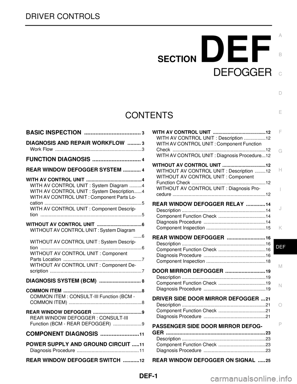
DEF-1
DRIVER CONTROLS
C
D
E
F
G
H
I
J
K
M
SECTION DEF
A
B
DEF
N
O
P
CONTENTS
DEFOGGER
BASIC INSPECTION ....................................3
DIAGNOSIS AND REPAIR WORKFLOW ..........3
Work Flow .................................................................3
FUNCTION DIAGNOSIS ...............................4
REAR WINDOW DEFOGGER SYSTEM .............4
WITH AV CONTROL UNIT ..........................................4
WITH AV CONTROL UNIT : System Diagram ..........4
WITH AV CONTROL UNIT : System Description ......4
WITH AV CONTROL UNIT : Component Parts Lo-
cation .........................................................................
5
WITH AV CONTROL UNIT : Component Descrip-
tion ............................................................................
5
WITHOUT AV CONTROL UNIT ..................................6
WITHOUT AV CONTROL UNIT : System Diagram
......
6
WITHOUT AV CONTROL UNIT : System Descrip-
tion ............................................................................
6
WITHOUT AV CONTROL UNIT : Component
Parts Location ...........................................................
7
WITHOUT AV CONTROL UNIT : Component De-
scription .....................................................................
7
DIAGNOSIS SYSTEM (BCM) .............................8
COMMON ITEM ...........................................................8
COMMON ITEM : CONSULT-III Function (BCM -
COMMON ITEM) .......................................................
8
REAR WINDOW DEFOGGER .....................................9
REAR WINDOW DEFOGGER : CONSULT-III
Function (BCM - REAR DEFOGGER) ......................
9
COMPONENT DIAGNOSIS .........................11
POWER SUPPLY AND GROUND CIRCUIT ......11
Diagnosis Procedure ...............................................11
REAR WINDOW DEFOGGER SWITCH ............12
WITH AV CONTROL UNIT ........................................12
WITH AV CONTROL UNIT : Description .................12
WITH AV CONTROL UNIT : Component Function
Check ......................................................................
12
WITH AV CONTROL UNIT : Diagnosis Procedure ....12
WITHOUT AV CONTROL UNIT .................................12
WITHOUT AV CONTROL UNIT : Description .........12
WITHOUT AV CONTROL UNIT : Component
Function Check ........................................................
12
WITHOUT AV CONTROL UNIT : Diagnosis Pro-
cedure ......................................................................
12
REAR WINDOW DEFOGGER RELAY .............14
Description ...............................................................14
Component Function Check ....................................14
Diagnosis Procedure ...............................................14
Component Inspection .............................................15
REAR WINDOW DEFOGGER ..........................16
Description ...............................................................16
Component Function Check ....................................16
Diagnosis Procedure ...............................................16
Component Inspection .............................................18
DOOR MIRROR DEFOGGER ...........................19
Description ...............................................................19
Component Function Check ....................................19
Diagnosis Procedure ...............................................19
DRIVER SIDE DOOR MIRROR DEFOGGER ...21
Description ...............................................................21
Component Function Check ....................................21
Diagnosis Procedure ...............................................21
PASSENGER SIDE DOOR MIRROR DEFOG-
GER ...................................................................
23
Description ...............................................................23
Component Function Check ....................................23
Diagnosis Procedure ...............................................23
REAR WINDOW DEFOGGER ON SIGNAL .....25
Page 1152 of 5121

DEF-2
Description ..............................................................25
Component Function Check ...................................25
Diagnosis Procedure ..............................................25
ECU DIAGNOSIS ........................................26
BCM (BODY CONTROL MODULE) ..................26
Reference Value .....................................................26
Wiring Diagram - DEFOGGER SYSTEM - .............49
Fail-safe ..................................................................53
DTC Inspection Priority Chart ..............................55
DTC Index ..............................................................56
SYMPTOM DIAGNOSIS .............................58
REAR WINDOW DEFOGGER AND DOOR
MIRROR DEFOGGER DO NOT OPERATE. .....
58
Diagnosis Procedure ..............................................58
REAR WINDOW DEFOGGER DOES NOT
OPERATE BUT BOTH DOOR MIRROR DE-
FOGGERS OPERATE. ......................................
59
Diagnosis Procedure ..............................................59
DOOR MIRROR DEFOGGER DOES NOT OP-
ERATE ...............................................................
60
BOTH SIDES .............................................................60
BOTH SIDES : Diagnosis Procedure .....................60
DRIVER SIDE ............................................................60
DRIVER SIDE : Diagnosis Procedure ....................60
PASSENGER SIDE ...................................................60
PASSENGER SIDE : Diagnosis Procedure ...........60
ON IS NOT DISPLAYED WHEN PRESSING
REAR WINDOW DEFOGGER SWITCH BUT
IT OPERATES ...................................................
61
WITH AV CONTROL UNIT ........................................61
WITH AV CONTROL UNIT : Diagnosis Procedure ...61
WITHOUT AV CONTROL UNIT ................................61
WITHOUT AV CONTROL UNIT : Diagnosis Pro-
cedure .....................................................................
61
REAR WINDOW DEFOGGER INDICATOR
DOES NOT ILLUMINATE ..................................
62
WITH AV CONTROL UNIT ........................................62
WITH AV CONTROL UNIT : Diagnosis Procedure ...62
WITHOUT AV CONTROL UNIT ................................62
WITHOUT AV CONTROL UNIT : Diagnosis Pro-
cedure .....................................................................
62
PRECAUTION ............................................63
PRECAUTIONS .................................................63
Precaution for Supplemental Restraint System
(SRS) "AIR BAG" and "SEAT BELT PRE-TEN-
SIONER" .................................................................
63
ON-VEHICLE REPAIR ...............................64
FILAMENT .........................................................64
Inspection and Repair .............................................64
CONDENSER ....................................................66
Exploded View ........................................................66
Removal and Installation .........................................66
Page 1154 of 5121
DEF-4
< FUNCTION DIAGNOSIS >
REAR WINDOW DEFOGGER SYSTEM
FUNCTION DIAGNOSIS
REAR WINDOW DEFOGGER SYSTEM
WITH AV CONTROL UNIT
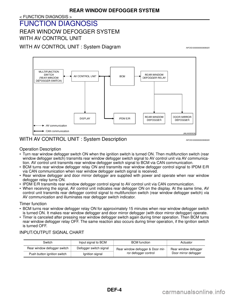
WITH AV CONTROL UNIT : System DiagramINFOID:0000000003806025
WITH AV CONTROL UNIT : System DescriptionINFOID:0000000003806026
Operation Description
Turn rear window defogger switch ON when the ignition switch is turned ON. Then multifunction switch (rear
window defogger switch) transmits rear window defogger switch signal to AV control unit via AV communica-
tion. AV control unit transmits rear window defogger switch signal to BCM via CAN communication.
BCM turns rear window defogger relay ON and transmits rear window defogger control signal to IPDM E/R
via CAN communication when rear window defogger switch signal is received.
Rear window defogger and door mirror defogger are supplied with power and operate when rear window
defogger relay turns ON.
IPDM E/R transmits rear window defogger control signal to AV control unit via CAN communication.
When receiving the signal, AV control unit indicates rear defogger ON on the display. At the same time, AV
control unit transmits rear defogger control signal to multifunction switch (rear window defogger switch) via
AV communication and illuminates rear defogger switch indicator.
Timer function
BCM turns rear window defogger relay ON for approximately 15 minutes when rear window defogger switch
is turned ON. It makes rear window defogger and door mirror defogger (with door mirror defogger) operate.
Timer is canceled after pressing rear window defogger switch again during timer operation. Then BCM turns
rear window defogger relay OFF. The same reaction also occurs during timer operation, if the ignition switch
is turned OFF.
INPUT/OUTPUT SIGNAL CHART
JMLIA0005GB
Switch Input signal to BCM BCM function Actuator
Rear window defogger switch Defogger switch signal
Rear window defogger & Door mir-
ror defogger controlRear window defogger
Door mirror defogger
Push button ignition switch Ignition signal
Page 1155 of 5121
REAR WINDOW DEFOGGER SYSTEM
DEF-5
< FUNCTION DIAGNOSIS >
C
D
E
F
G
H
I
J
K
MA
B
DEF
N
O
P
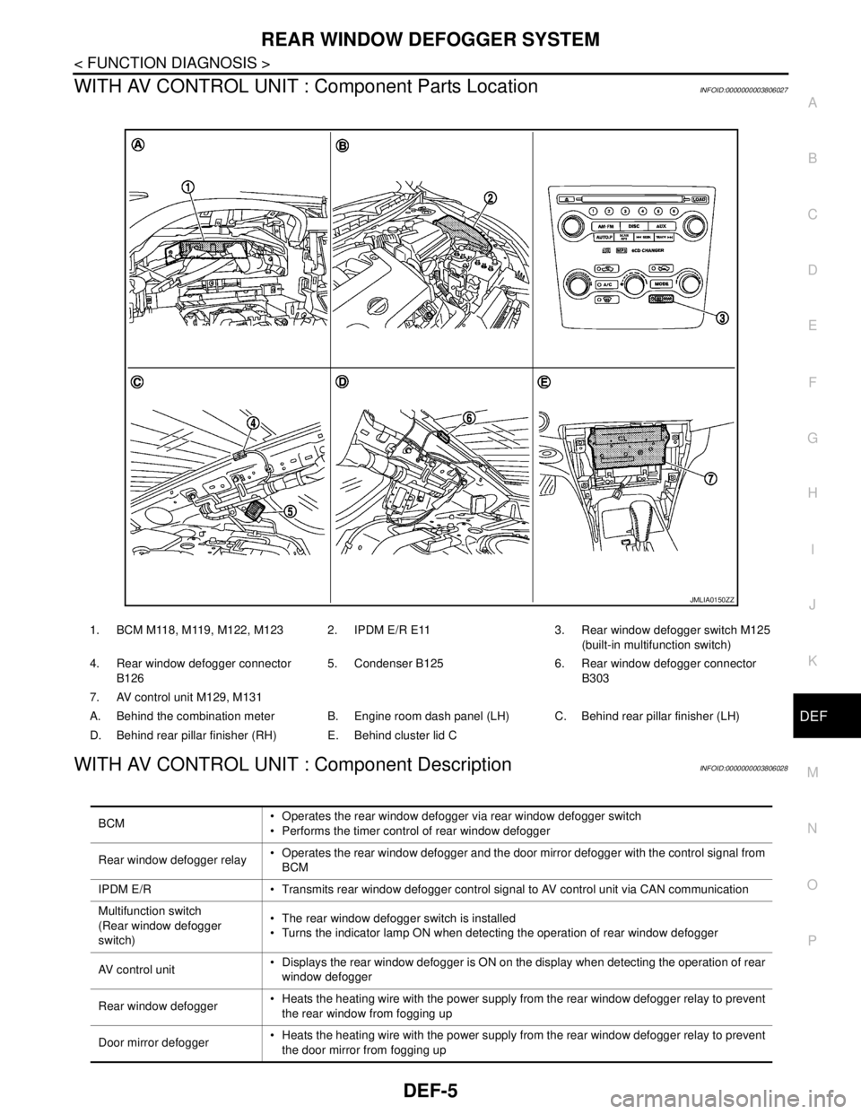
WITH AV CONTROL UNIT : Component Parts LocationINFOID:0000000003806027
WITH AV CONTROL UNIT : Component DescriptionINFOID:0000000003806028
1. BCM M118, M119, M122, M123 2. IPDM E/R E11 3. Rear window defogger switch M125
(built-in multifunction switch)
4. Rear window defogger connector
B1265. Condenser B125 6. Rear window defogger connector
B303
7. AV control unit M129, M131
A. Behind the combination meter B. Engine room dash panel (LH) C. Behind rear pillar finisher (LH)
D. Behind rear pillar finisher (RH) E. Behind cluster lid C
JMLIA0150ZZ
BCM Operates the rear window defogger via rear window defogger switch
Performs the timer control of rear window defogger
Rear window defogger relay Operates the rear window defogger and the door mirror defogger with the control signal from
BCM
IPDM E/R Transmits rear window defogger control signal to AV control unit via CAN communication
Multifunction switch
(Rear window defogger
switch) The rear window defogger switch is installed
Turns the indicator lamp ON when detecting the operation of rear window defogger
AV control unit Displays the rear window defogger is ON on the display when detecting the operation of rear
window defogger
Rear window defogger Heats the heating wire with the power supply from the rear window defogger relay to prevent
the rear window from fogging up
Door mirror defogger Heats the heating wire with the power supply from the rear window defogger relay to prevent
the door mirror from fogging up
Page 1156 of 5121
DEF-6
< FUNCTION DIAGNOSIS >
REAR WINDOW DEFOGGER SYSTEM
WITHOUT AV CONTROL UNIT
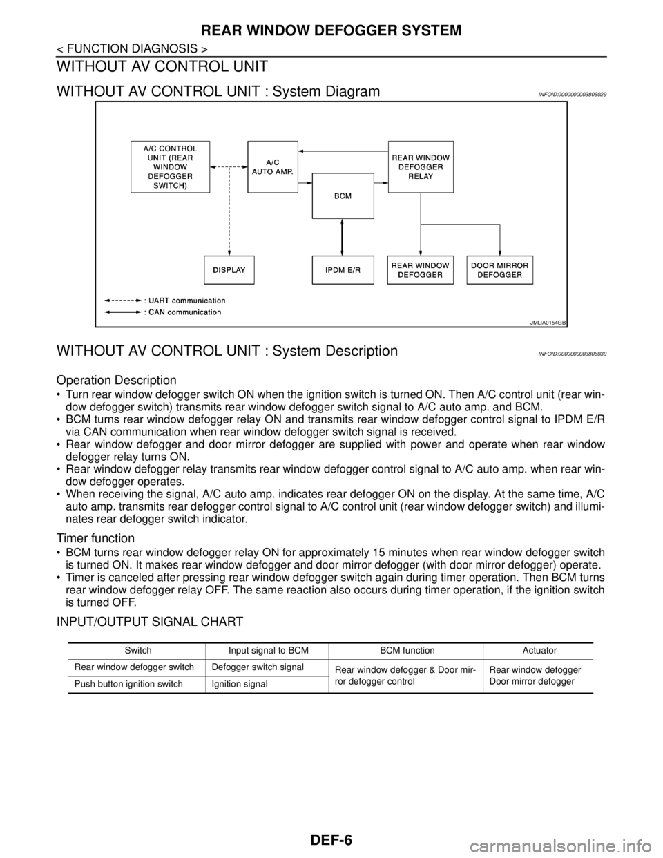
WITHOUT AV CONTROL UNIT : System DiagramINFOID:0000000003806029
WITHOUT AV CONTROL UNIT : System DescriptionINFOID:0000000003806030
Operation Description
Turn rear window defogger switch ON when the ignition switch is turned ON. Then A/C control unit (rear win-
dow defogger switch) transmits rear window defogger switch signal to A/C auto amp. and BCM.
BCM turns rear window defogger relay ON and transmits rear window defogger control signal to IPDM E/R
via CAN communication when rear window defogger switch signal is received.
Rear window defogger and door mirror defogger are supplied with power and operate when rear window
defogger relay turns ON.
Rear window defogger relay transmits rear window defogger control signal to A/C auto amp. when rear win-
dow defogger operates.
When receiving the signal, A/C auto amp. indicates rear defogger ON on the display. At the same time, A/C
auto amp. transmits rear defogger control signal to A/C control unit (rear window defogger switch) and illumi-
nates rear defogger switch indicator.
Timer function
BCM turns rear window defogger relay ON for approximately 15 minutes when rear window defogger switch
is turned ON. It makes rear window defogger and door mirror defogger (with door mirror defogger) operate.
Timer is canceled after pressing rear window defogger switch again during timer operation. Then BCM turns
rear window defogger relay OFF. The same reaction also occurs during timer operation, if the ignition switch
is turned OFF.
INPUT/OUTPUT SIGNAL CHART
JMLIA0154GB
Switch Input signal to BCM BCM function Actuator
Rear window defogger switch Defogger switch signal
Rear window defogger & Door mir-
ror defogger controlRear window defogger
Door mirror defogger
Push button ignition switch Ignition signal
Page 1157 of 5121
REAR WINDOW DEFOGGER SYSTEM
DEF-7
< FUNCTION DIAGNOSIS >
C
D
E
F
G
H
I
J
K
MA
B
DEF
N
O
P
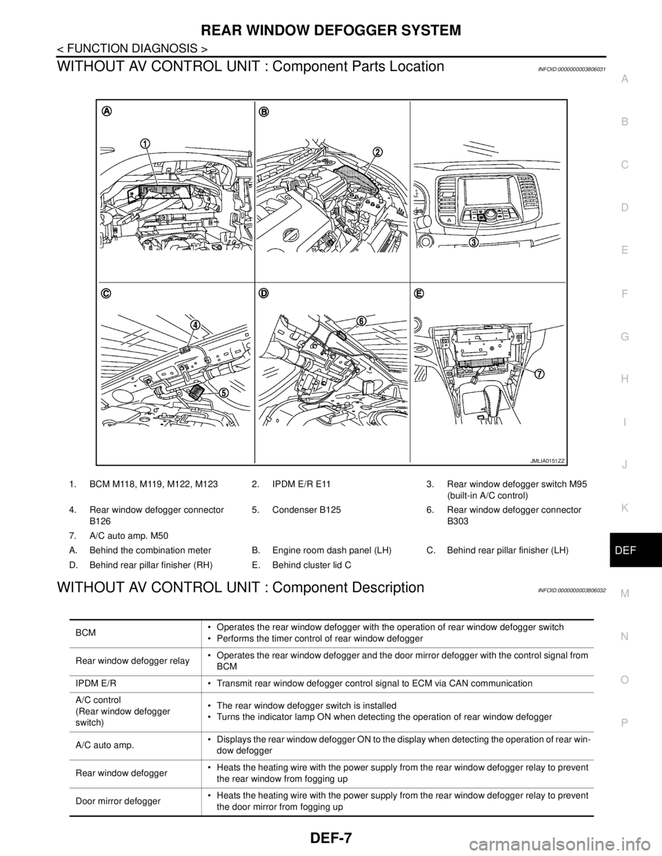
WITHOUT AV CONTROL UNIT : Component Parts LocationINFOID:0000000003806031
WITHOUT AV CONTROL UNIT : Component DescriptionINFOID:0000000003806032
1. BCM M118, M119, M122, M123 2. IPDM E/R E11 3. Rear window defogger switch M95
(built-in A/C control)
4. Rear window defogger connector
B1265. Condenser B125 6. Rear window defogger connector
B303
7. A/C auto amp. M50
A. Behind the combination meter B. Engine room dash panel (LH) C. Behind rear pillar finisher (LH)
D. Behind rear pillar finisher (RH) E. Behind cluster lid C
JMLIA0151ZZ
BCM Operates the rear window defogger with the operation of rear window defogger switch
Performs the timer control of rear window defogger
Rear window defogger relay Operates the rear window defogger and the door mirror defogger with the control signal from
BCM
IPDM E/R Transmit rear window defogger control signal to ECM via CAN communication
A/C control
(Rear window defogger
switch) The rear window defogger switch is installed
Turns the indicator lamp ON when detecting the operation of rear window defogger
A/C auto amp. Displays the rear window defogger ON to the display when detecting the operation of rear win-
dow defogger
Rear window defogger Heats the heating wire with the power supply from the rear window defogger relay to prevent
the rear window from fogging up
Door mirror defogger Heats the heating wire with the power supply from the rear window defogger relay to prevent
the door mirror from fogging up