Page 1196 of 5121

DEF-46
< ECU DIAGNOSIS >
BCM (BODY CONTROL MODULE)
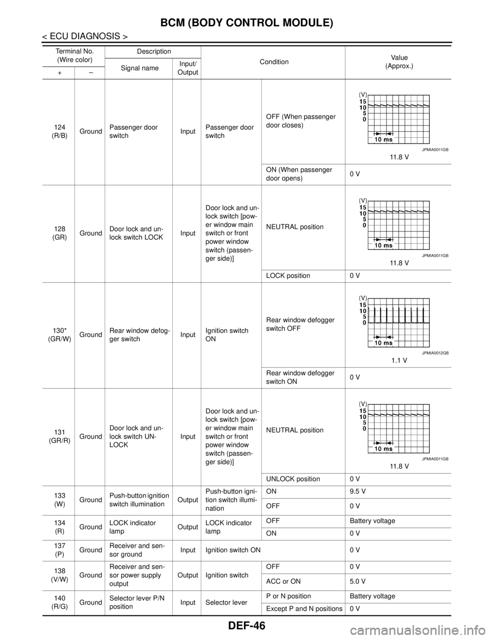
124
(R/B)GroundPassenger door
switchInputPassenger door
switchOFF (When passenger
door closes)
11 . 8 V
ON (When passenger
door opens)0 V
128
(GR)GroundDoor lock and un-
lock switch LOCKInputDoor lock and un-
lock switch [pow-
er window main
switch or front
power window
switch (passen-
ger side)]NEUTRAL position
11 . 8 V
LOCK position 0 V
130*
(GR/W)GroundRear window defog-
ger switchInputIgnition switch
ONRear window defogger
switch OFF
1.1 V
Rear window defogger
switch ON0 V
131
(GR/R)GroundDoor lock and un-
lock switch UN-
LOCKInputDoor lock and un-
lock switch [pow-
er window main
switch or front
power window
switch (passen-
ger side)]NEUTRAL position
11 . 8 V
UNLOCK position 0 V
133
(W)GroundPush-button ignition
switch illuminationOutputPush-button igni-
tion switch illumi-
nationON 9.5 V
OFF 0 V
134
(R)GroundLOCK indicator
lampOutputLOCK indicator
lampOFF Battery voltage
ON 0 V
137
(P)GroundReceiver and sen-
sor groundInput Ignition switch ON 0 V
138
(V/W)GroundReceiver and sen-
sor power supply
outputOutput Ignition switchOFF 0 V
ACC or ON 5.0 V
140
(R/G)GroundSelector lever P/N
positionInput Selector leverP or N position Battery voltage
Except P and N positions 0 V Te r m i n a l N o .
(Wire color)Description
ConditionVa l u e
(Approx.)
Signal nameInput/
Output +–
JPMIA0011GB
JPMIA0011GB
JPMIA0012GB
JPMIA0011GB
Page 1198 of 5121
DEF-48
< ECU DIAGNOSIS >
BCM (BODY CONTROL MODULE)
NOTE:
*: Without BOSE audio system145
(LG/R)GroundCombination switch
OUTPUT 3OutputCombination
switch
(Wiper intermit-
tent dial 4)All switch OFF 0 V
Front wiper switch INT
10.7 V Front wiper switch LO
Lighting switch AUTO
Rear fog lamp switch ON
146
(G/Y)GroundCombination switch
OUTPUT 4OutputCombination
switch
(Wiper intermit-
tent dial 4)All switch OFF 0 V
Front fog lamp switch ON
10.7 V Lighting switch 2ND
Lighting switch PASS
Turn signal switch LH
150
(SB)Ground Driver door switch Input Driver door switchOFF (When driver door
closes)
11 . 8 V
ON (When driver door
opens)0 V
151
(G/R)GroundRear window defog-
ger relayOutputRear window de-
foggerActive 0 V
Not activated Battery voltage Te r m i n a l N o .
(Wire color)Description
ConditionVa l u e
(Approx.)
Signal nameInput/
Output +–
JPMIA0034GB
JPMIA0035GB
JPMIA0011GB
Page 1208 of 5121

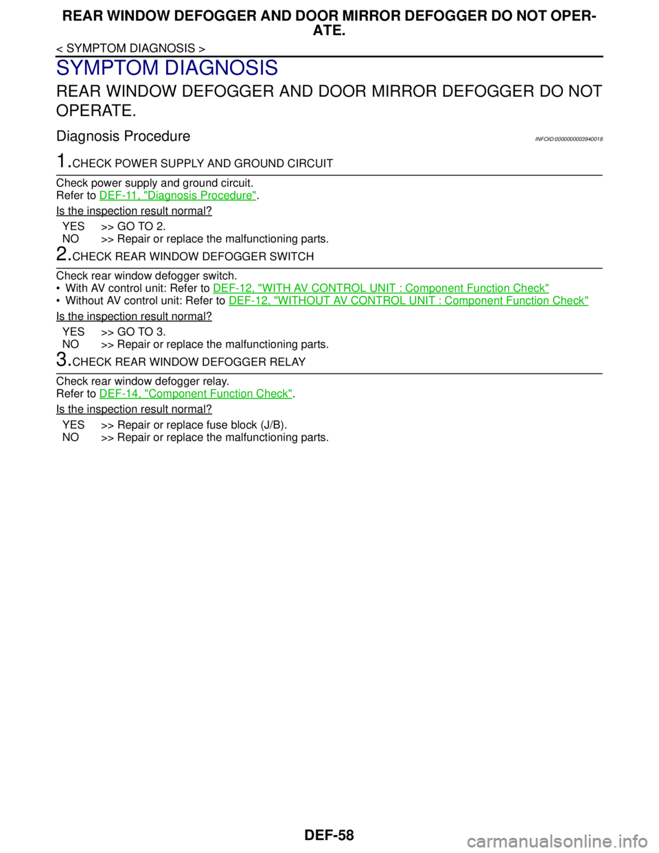
DEF-58
< SYMPTOM DIAGNOSIS >
REAR WINDOW DEFOGGER AND DOOR MIRROR DEFOGGER DO NOT OPER-
ATE.
SYMPTOM DIAGNOSIS
REAR WINDOW DEFOGGER AND DOOR MIRROR DEFOGGER DO NOT
OPERATE.
Diagnosis ProcedureINFOID:0000000003940018
1.CHECK POWER SUPPLY AND GROUND CIRCUIT
Check power supply and ground circuit.
Refer to DEF-11, "
Diagnosis Procedure".
Is the inspection result normal?
YES >> GO TO 2.
NO >> Repair or replace the malfunctioning parts.
2.CHECK REAR WINDOW DEFOGGER SWITCH
Check rear window defogger switch.
With AV control unit: Refer to DEF-12, "
WITH AV CONTROL UNIT : Component Function Check"
Without AV control unit: Refer to DEF-12, "WITHOUT AV CONTROL UNIT : Component Function Check"
Is the inspection result normal?
YES >> GO TO 3.
NO >> Repair or replace the malfunctioning parts.
3.CHECK REAR WINDOW DEFOGGER RELAY
Check rear window defogger relay.
Refer to DEF-14, "
Component Function Check".
Is the inspection result normal?
YES >> Repair or replace fuse block (J/B).
NO >> Repair or replace the malfunctioning parts.
Page 1209 of 5121
REAR WINDOW DEFOGGER DOES NOT OPERATE BUT BOTH DOOR MIRROR
DEFOGGERS OPERATE.
DEF-59
< SYMPTOM DIAGNOSIS >
C
D
E
F
G
H
I
J
K
MA
B
DEF
N
O
P
REAR WINDOW DEFOGGER DOES NOT OPERATE BUT BOTH DOOR
MIRROR DEFOGGERS OPERATE.
Diagnosis ProcedureINFOID:0000000003806065
1.CHECK REAR WINDOW DEFOGGER
Check rear window defogger.
Refer to DEF-16, "
Component Function Check".
Is the inspection result normal?
YES >> GO TO 2.
NO >> Repair or replace the malfunctioning parts.
2.CONFIRM THE OPERATION
Confirm the operation again
Is the inspection result normal?
YES >> Check intermittent incident. Refer to GI-35, "Intermittent Incident".
NO >> GO TO 1.
Page 1211 of 5121

ON IS NOT DISPLAYED WHEN PRESSING REAR WINDOW DEFOGGER
SWITCH BUT IT OPERATES
DEF-61
< SYMPTOM DIAGNOSIS >
C
D
E
F
G
H
I
J
K
MA
B
DEF
N
O
P
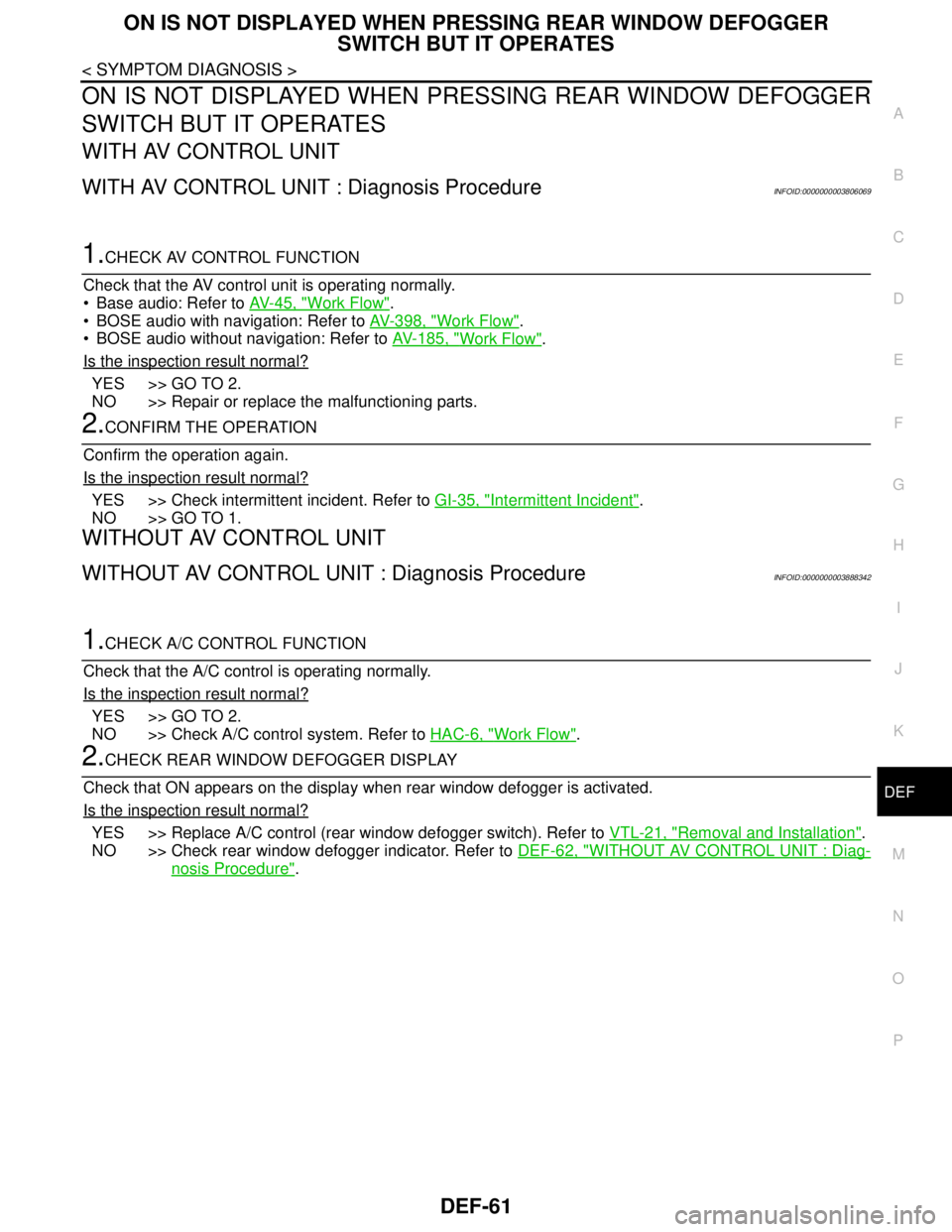
ON IS NOT DISPLAYED WHEN PRESSING REAR WINDOW DEFOGGER
SWITCH BUT IT OPERATES
WITH AV CONTROL UNIT
WITH AV CONTROL UNIT : Diagnosis ProcedureINFOID:0000000003806069
1.CHECK AV CONTROL FUNCTION
Check that the AV control unit is operating normally.
Base audio: Refer to AV-45, "
Work Flow".
BOSE audio with navigation: Refer to AV-398, "
Work Flow".
BOSE audio without navigation: Refer to AV-185, "
Work Flow".
Is the inspection result normal?
YES >> GO TO 2.
NO >> Repair or replace the malfunctioning parts.
2.CONFIRM THE OPERATION
Confirm the operation again.
Is the inspection result normal?
YES >> Check intermittent incident. Refer to GI-35, "Intermittent Incident".
NO >> GO TO 1.
WITHOUT AV CONTROL UNIT
WITHOUT AV CONTROL UNIT : Diagnosis ProcedureINFOID:0000000003888342
1.CHECK A/C CONTROL FUNCTION
Check that the A/C control is operating normally.
Is the inspection result normal?
YES >> GO TO 2.
NO >> Check A/C control system. Refer to HAC-6, "
Work Flow".
2.CHECK REAR WINDOW DEFOGGER DISPLAY
Check that ON appears on the display when rear window defogger is activated.
Is the inspection result normal?
YES >> Replace A/C control (rear window defogger switch). Refer to VTL-21, "Removal and Installation".
NO >> Check rear window defogger indicator. Refer to DEF-62, "
WITHOUT AV CONTROL UNIT : Diag-
nosis Procedure".
Page 1212 of 5121

DEF-62
< SYMPTOM DIAGNOSIS >
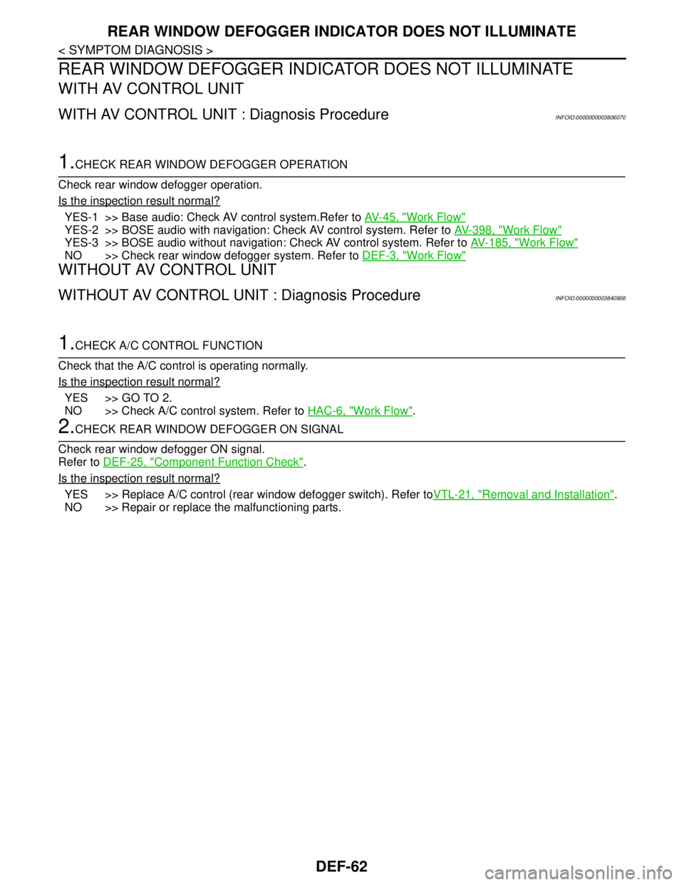
REAR WINDOW DEFOGGER INDICATOR DOES NOT ILLUMINATE
REAR WINDOW DEFOGGER INDICATOR DOES NOT ILLUMINATE
WITH AV CONTROL UNIT
WITH AV CONTROL UNIT : Diagnosis ProcedureINFOID:0000000003806070
1.CHECK REAR WINDOW DEFOGGER OPERATION
Check rear window defogger operation.
Is the inspection result normal?
YES-1 >> Base audio: Check AV control system.Refer to AV-45, "Work Flow"
YES-2 >> BOSE audio with navigation: Check AV control system. Refer to AV-398, "Work Flow"
YES-3 >> BOSE audio without navigation: Check AV control system. Refer to AV-185, "Work Flow"
NO >> Check rear window defogger system. Refer to DEF-3, "Work Flow"
WITHOUT AV CONTROL UNIT
WITHOUT AV CONTROL UNIT : Diagnosis ProcedureINFOID:0000000003840906
1.CHECK A/C CONTROL FUNCTION
Check that the A/C control is operating normally.
Is the inspection result normal?
YES >> GO TO 2.
NO >> Check A/C control system. Refer to HAC-6, "
Work Flow".
2.CHECK REAR WINDOW DEFOGGER ON SIGNAL
Check rear window defogger ON signal.
Refer to DEF-25, "
Component Function Check".
Is the inspection result normal?
YES >> Replace A/C control (rear window defogger switch). Refer toVTL-21, "Removal and Installation".
NO >> Repair or replace the malfunctioning parts.
Page 1227 of 5121
![NISSAN TEANA 2008 Service Manual POWER DOOR LOCK SYSTEM
DLK-11
< FUNCTION DIAGNOSIS >[WITH INTELLIGENT KEY SYSTEM]
C
D
E
F
G
H
I
J
L
MA
B
DLK
N
O
P
FUNCTION DIAGNOSIS
POWER DOOR LOCK SYSTEM
System DiagramINFOID:0000000003794734
Syste NISSAN TEANA 2008 Service Manual POWER DOOR LOCK SYSTEM
DLK-11
< FUNCTION DIAGNOSIS >[WITH INTELLIGENT KEY SYSTEM]
C
D
E
F
G
H
I
J
L
MA
B
DLK
N
O
P
FUNCTION DIAGNOSIS
POWER DOOR LOCK SYSTEM
System DiagramINFOID:0000000003794734
Syste](/manual-img/5/57391/w960_57391-1226.png)
POWER DOOR LOCK SYSTEM
DLK-11
< FUNCTION DIAGNOSIS >[WITH INTELLIGENT KEY SYSTEM]
C
D
E
F
G
H
I
J
L
MA
B
DLK
N
O
P
FUNCTION DIAGNOSIS
POWER DOOR LOCK SYSTEM
System DiagramINFOID:0000000003794734
System DescriptionINFOID:0000000003794735
DOOR LOCK FUNCTION
The door lock and unlock switch (driver side) are build into power window main switch.
Interlocked with the locking operation of door lock and unlock switch, door lock actuators of all doors are
locked.
Interlocked with the unlocking operation of door lock and unlock switch, door lock actuators of all doors and
are unlocked.
When ignition switch is ON and BCM receives air bag deployment signal, it operates automatically to unlock
all doors. Air bag diagnosis sensor unit sends the air bag deployment signal to BCM.
Door Key Cylinder
With the door key inserted in the door key cylinder on driver side, turning the door key cylinder to “LOCK”,
locks door lock actuator of driver side door.
With the door key inserted in the door key cylinder on driver side, turning the door key cylinder to “UNLOCK”,
unlocks door lock actuator of driver side door.
JMKIA2372GB
Page 1228 of 5121
DLK-12
< FUNCTION DIAGNOSIS >[WITH INTELLIGENT KEY SYSTEM]
POWER DOOR LOCK SYSTEM
Component Parts Location
INFOID:0000000003794736
Component DescriptionINFOID:0000000003794737
1. BCM M118, M119, M121, M122, M123 2. TCM F23 3. Combination meter M34
4. Key slot M99 5. Power window main switch
(door lock and unlock switch) D5, D66. Front door switch (driver side) B34
7. Front door lock assembly (driver side) D9
A. Behind the combination meter B. Engine room LH C. View with front door finisher re-
moved
JMKIA2373ZZ
Item Function
BCM Controls the door lock function and room lamp function.
Door lock and unlock switch Inputs lock or unlock signal to BCM.
Front door lock assembly (door lock actu-
ator)Outputs lock/unlock signal from BCM and locks/unlocks each door.