2008 NISSAN TEANA Ccu
[x] Cancel search: CcuPage 3140 of 5121
![NISSAN TEANA 2008 Service Manual LAN
CAN COMMUNICATION CIRCUIT
LAN-73
< COMPONENT DIAGNOSIS >[CAN SYSTEM (TYPE 4)]
C
D
E
F
G
H
I
J
K
L B A
O
P N
Inspection result
Reproduced>>GO TO 6.
Non-reproduced>>Start the diagnosis again. Follow NISSAN TEANA 2008 Service Manual LAN
CAN COMMUNICATION CIRCUIT
LAN-73
< COMPONENT DIAGNOSIS >[CAN SYSTEM (TYPE 4)]
C
D
E
F
G
H
I
J
K
L B A
O
P N
Inspection result
Reproduced>>GO TO 6.
Non-reproduced>>Start the diagnosis again. Follow](/manual-img/5/57391/w960_57391-3139.png)
LAN
CAN COMMUNICATION CIRCUIT
LAN-73
< COMPONENT DIAGNOSIS >[CAN SYSTEM (TYPE 4)]
C
D
E
F
G
H
I
J
K
L B A
O
P N
Inspection result
Reproduced>>GO TO 6.
Non-reproduced>>Start the diagnosis again. Follow the trouble diagnosis procedure when past error is
detected.
6.CHECK UNIT REPRODUCTION
Perform the reproduction test as per the following procedure for each unit.
1. Turn the ignition switch OFF.
2. Disconnect the battery cable from the negative terminal.
3. Disconnect one of the unit connectors of CAN communication system.
NOTE:
ECM and IPDM E/R have a termination circuit. Check other units first.
4. Connect the battery cable to the negative terminal. Check if the symptoms described in the “Symptom
(Results from interview with customer)” are reproduced.
NOTE:
Although unit-related error symptoms occur, do not confuse them with other symptoms.
Inspection result
Reproduced>>Connect the connector. Check other units as per the above procedure.
Non-reproduced>>Replace the unit whose connector was disconnected.
Page 3156 of 5121
![NISSAN TEANA 2008 Service Manual LAN
CAN COMMUNICATION CIRCUIT
LAN-89
< COMPONENT DIAGNOSIS >[CAN SYSTEM (TYPE 6)]
C
D
E
F
G
H
I
J
K
L B A
O
P N
Inspection result
Reproduced>>GO TO 6.
Non-reproduced>>Start the diagnosis again. Follow NISSAN TEANA 2008 Service Manual LAN
CAN COMMUNICATION CIRCUIT
LAN-89
< COMPONENT DIAGNOSIS >[CAN SYSTEM (TYPE 6)]
C
D
E
F
G
H
I
J
K
L B A
O
P N
Inspection result
Reproduced>>GO TO 6.
Non-reproduced>>Start the diagnosis again. Follow](/manual-img/5/57391/w960_57391-3155.png)
LAN
CAN COMMUNICATION CIRCUIT
LAN-89
< COMPONENT DIAGNOSIS >[CAN SYSTEM (TYPE 6)]
C
D
E
F
G
H
I
J
K
L B A
O
P N
Inspection result
Reproduced>>GO TO 6.
Non-reproduced>>Start the diagnosis again. Follow the trouble diagnosis procedure when past error is
detected.
6.CHECK UNIT REPRODUCTION
Perform the reproduction test as per the following procedure for each unit.
1. Turn the ignition switch OFF.
2. Disconnect the battery cable from the negative terminal.
3. Disconnect one of the unit connectors of CAN communication system.
NOTE:
ECM and IPDM E/R have a termination circuit. Check other units first.
4. Connect the battery cable to the negative terminal. Check if the symptoms described in the “Symptom
(Results from interview with customer)” are reproduced.
NOTE:
Although unit-related error symptoms occur, do not confuse them with other symptoms.
Inspection result
Reproduced>>Connect the connector. Check other units as per the above procedure.
Non-reproduced>>Replace the unit whose connector was disconnected.
Page 3172 of 5121
![NISSAN TEANA 2008 Service Manual LAN
CAN COMMUNICATION CIRCUIT
LAN-105
< COMPONENT DIAGNOSIS >[CAN SYSTEM (TYPE 9)]
C
D
E
F
G
H
I
J
K
L B A
O
P N
Inspection result
Reproduced>>GO TO 6.
Non-reproduced>>Start the diagnosis again. Follo NISSAN TEANA 2008 Service Manual LAN
CAN COMMUNICATION CIRCUIT
LAN-105
< COMPONENT DIAGNOSIS >[CAN SYSTEM (TYPE 9)]
C
D
E
F
G
H
I
J
K
L B A
O
P N
Inspection result
Reproduced>>GO TO 6.
Non-reproduced>>Start the diagnosis again. Follo](/manual-img/5/57391/w960_57391-3171.png)
LAN
CAN COMMUNICATION CIRCUIT
LAN-105
< COMPONENT DIAGNOSIS >[CAN SYSTEM (TYPE 9)]
C
D
E
F
G
H
I
J
K
L B A
O
P N
Inspection result
Reproduced>>GO TO 6.
Non-reproduced>>Start the diagnosis again. Follow the trouble diagnosis procedure when past error is
detected.
6.CHECK UNIT REPRODUCTION
Perform the reproduction test as per the following procedure for each unit.
1. Turn the ignition switch OFF.
2. Disconnect the battery cable from the negative terminal.
3. Disconnect one of the unit connectors of CAN communication system.
NOTE:
ECM and IPDM E/R have a termination circuit. Check other units first.
4. Connect the battery cable to the negative terminal. Check if the symptoms described in the “Symptom
(Results from interview with customer)” are reproduced.
NOTE:
Although unit-related error symptoms occur, do not confuse them with other symptoms.
Inspection result
Reproduced>>Connect the connector. Check other units as per the above procedure.
Non-reproduced>>Replace the unit whose connector was disconnected.
Page 3199 of 5121

RECOMMENDED FLUIDS AND LUBRICANTS
MA-11
< ON-VEHICLE MAINTENANCE >
C
D
E
F
G
H
I
J
K
L
MB
MAN
OA
RECOMMENDED FLUIDS AND LUBRICANTS
Fluids and LubricantsINFOID:0000000003858223
*1: For further details, see “SAE Viscosity Number”.
*2: Use Genuine NISSAN Engine Coolant or equivalent in its quality, in order to avoid possible aluminum corrosion within the engine
cooling system caused by the use of non-genuine engine coolant.
Note that any repairs for the incidents within the engine cooling system while using non-genuine engine coolant may not be
covered by the warranty even if such incidents occurred during the warranty period.
*3: Using transmission fluid other than Genuine NISSAN CVT fluid NS-2 will damage the CVT, which is not covered by the war-
ranty.
*4: DEXRON
™ VI type ATF can be used.
*5: Never mix different types of fluids (DOT3 and DOT4).
SAE Viscosity NumberINFOID:0000000003858224
GASOLINE ENGINE
5W-30 is preferable.
Capacity (Approximate)
Recommended Fluids/Lubricants
LiterImp mea-
sure
Engine oil
Drain and refillWith oil filter change 4.6 4 qt
Genuine NISSAN engine oil
*1
API grade SL or SM*1
ILSAC grade GF-3 or GF-4*1
ACEA A1/B1, A3/B3, A3/B4, A5/B5, C2 or C3*1
Without oil filter
change4.3 3-3/4 qt
Dry engine (engine overhaul) 5.3 4-5/8 qt
Cooling system (with reservoir) 9.1 8 qt
Genuine NISSAN Engine Coolant or equivalent
in its quality
*2Reservoir tank 0.8 3/4 qt
CVT fluidRE0F10A 8.3 7-1/4 qt
Genuine NISSAN CVT Fluid NS-2
*3
RE0F09B 10.2 9 qt
Power steering fluid 1.0 7/8 qt
Genuine NISSAN PSF or equivalent
*4
Brake fluid — —Genuine NISSAN brake fluid, or equivalent DOT
3 or DOT4 (US FMVSS No. 116)*5
Multi-purpose grease — — NLGI No. 2 (Lithium soap base)
Page 3202 of 5121

MA-14
< ON-VEHICLE MAINTENANCE >
ENGINE MAINTENANCE
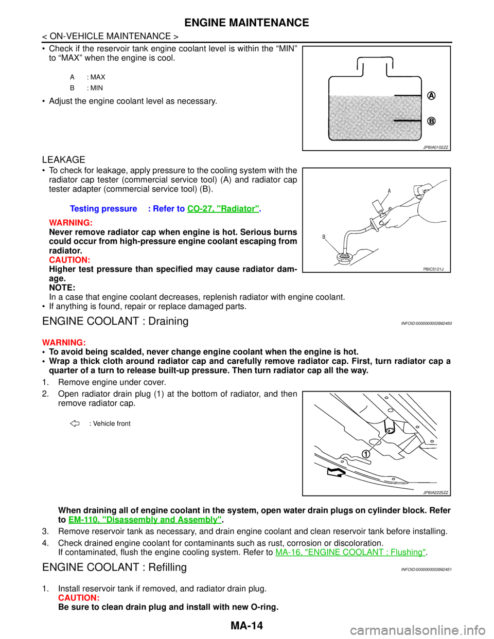
Check if the reservoir tank engine coolant level is within the “MIN”
to “MAX” when the engine is cool.
Adjust the engine coolant level as necessary.
LEAKAGE
To check for leakage, apply pressure to the cooling system with the
radiator cap tester (commercial service tool) (A) and radiator cap
tester adapter (commercial service tool) (B).
WARNING:
Never remove radiator cap when engine is hot. Serious burns
could occur from high-pressure engine coolant escaping from
radiator.
CAUTION:
Higher test pressure than specified may cause radiator dam-
age.
NOTE:
In a case that engine coolant decreases, replenish radiator with engine coolant.
If anything is found, repair or replace damaged parts.
ENGINE COOLANT : DrainingINFOID:0000000003862450
WARNING:
To avoid being scalded, never change engine coolant when the engine is hot.
Wrap a thick cloth around radiator cap and carefully remove radiator cap. First, turn radiator cap a
quarter of a turn to release built-up pressure. Then turn radiator cap all the way.
1. Remove engine under cover.
2. Open radiator drain plug (1) at the bottom of radiator, and then
remove radiator cap.
When draining all of engine coolant in the system, open water drain plugs on cylinder block. Refer
to EM-110, "
Disassembly and Assembly".
3. Remove reservoir tank as necessary, and drain engine coolant and clean reservoir tank before installing.
4. Check drained engine coolant for contaminants such as rust, corrosion or discoloration.
If contaminated, flush the engine cooling system. Refer to MA-16, "
ENGINE COOLANT : Flushing".
ENGINE COOLANT : RefillingINFOID:0000000003862451
1. Install reservoir tank if removed, and radiator drain plug.
CAUTION:
Be sure to clean drain plug and install with new O-ring.
A: MAX
B: MIN
JPBIA0102ZZ
Testing pressure : Refer to CO-27, "Radiator".
PBIC5121J
: Vehicle front
JPBIA2225ZZ
Page 3228 of 5121

MA-40
< ON-VEHICLE MAINTENANCE >
CHASSIS MAINTENANCE
POWER STEERING FLUID AND LINES : Inspection
INFOID:0000000003862441
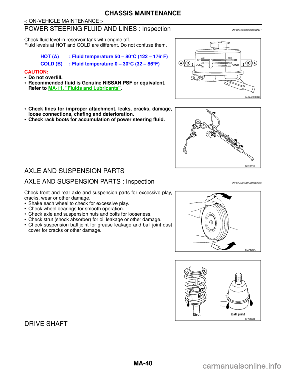
Check fluid level in reservoir tank with engine off.
Fluid levels at HOT and COLD are different. Do not confuse them.
CAUTION:
Do not overfill.
Recommended fluid is Genuine NISSAN PSF or equivalent.
Refer to MA-11, "
Fluids and Lubricants".
Check lines for improper attachment, leaks, cracks, damage,
loose connections, chafing and deterioration.
Check rack boots for accumulation of power steering fluid.
AXLE AND SUSPENSION PARTS
AXLE AND SUSPENSION PARTS : InspectionINFOID:0000000003858316
Check front and rear axle and suspension parts for excessive play,
cracks, wear or other damage.
Shake each wheel to check for excessive play.
Check wheel bearings for smooth operation.
Check axle and suspension nuts and bolts for looseness.
Check strut (shock absorber) for oil leakage or other damage.
Check suspension ball joint for grease leakage and ball joint dust
cover for cracks or other damage.
DRIVE SHAFT
HOT (A) : Fluid temperature 50 – 80°C (122 – 176°F)
COLD (B) : Fluid temperature 0 – 30°C (32 – 86°F)
ALGIA0002GB
SST851C
SMA525A
SFA392B
Page 3239 of 5121

MIR-6
< SYMPTOM DIAGNOSIS >
SQUEAK AND RATTLE TROUBLE DIAGNOSES
SYMPTOM DIAGNOSIS
SQUEAK AND RATTLE TROUBLE DIAGNOSES
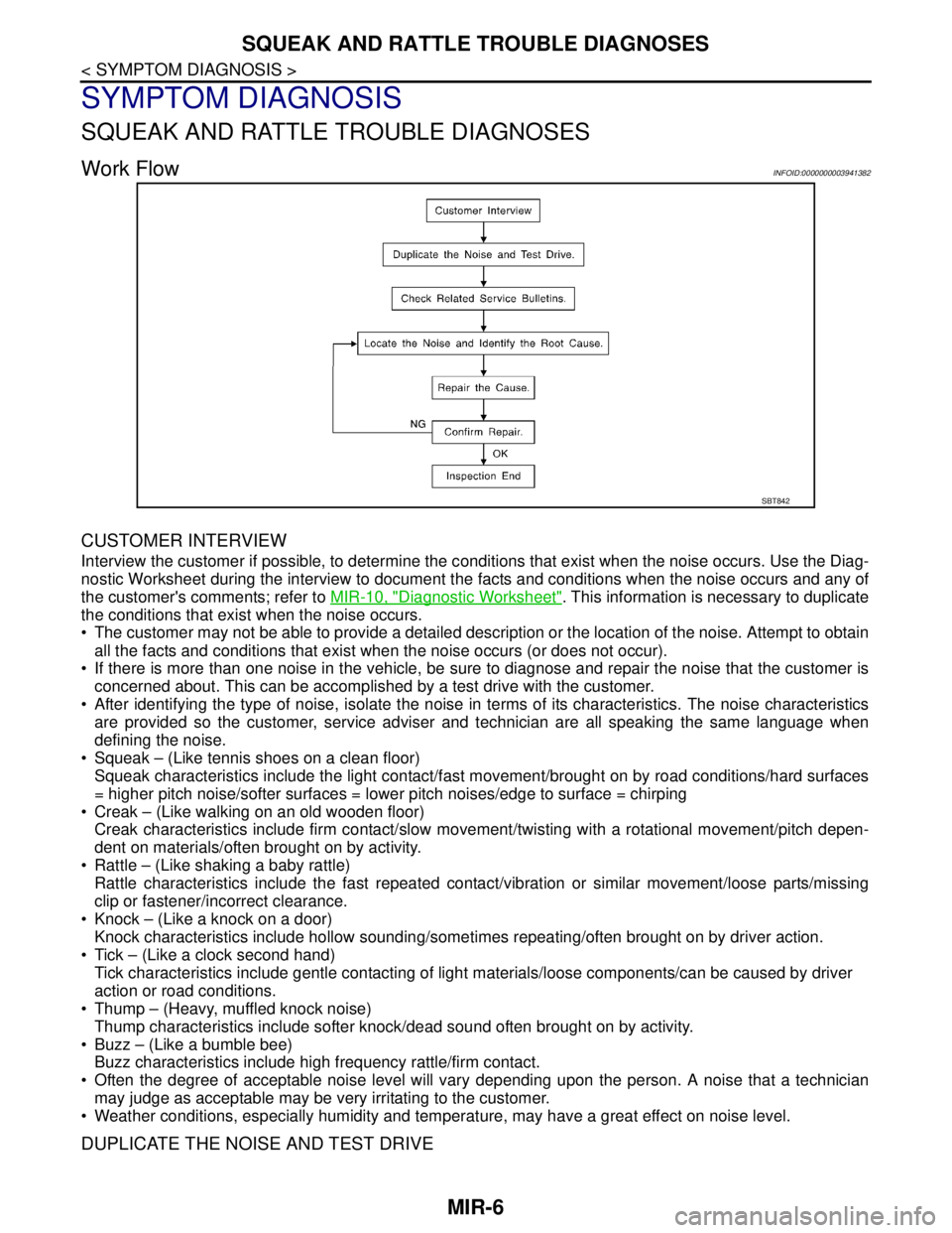
Work FlowINFOID:0000000003941382
CUSTOMER INTERVIEW
Interview the customer if possible, to determine the conditions that exist when the noise occurs. Use the Diag-
nostic Worksheet during the interview to document the facts and conditions when the noise occurs and any of
the customer's comments; refer to MIR-10, "
Diagnostic Worksheet". This information is necessary to duplicate
the conditions that exist when the noise occurs.
• The customer may not be able to provide a detailed description or the location of the noise. Attempt to obtain
all the facts and conditions that exist when the noise occurs (or does not occur).
If there is more than one noise in the vehicle, be sure to diagnose and repair the noise that the customer is
concerned about. This can be accomplished by a test drive with the customer.
After identifying the type of noise, isolate the noise in terms of its characteristics. The noise characteristics
are provided so the customer, service adviser and technician are all speaking the same language when
defining the noise.
Squeak – (Like tennis shoes on a clean floor)
Squeak characteristics include the light contact/fast movement/brought on by road conditions/hard surfaces
= higher pitch noise/softer surfaces = lower pitch noises/edge to surface = chirping
Creak – (Like walking on an old wooden floor)
Creak characteristics include firm contact/slow movement/twisting with a rotational movement/pitch depen-
dent on materials/often brought on by activity.
Rattle – (Like shaking a baby rattle)
Rattle characteristics include the fast repeated contact/vibration or similar movement/loose parts/missing
clip or fastener/incorrect clearance.
Knock – (Like a knock on a door)
Knock characteristics include hollow sounding/sometimes repeating/often brought on by driver action.
Tick – (Like a clock second hand)
Tick characteristics include gentle contacting of light materials/loose components/can be caused by driver
action or road conditions.
Thump – (Heavy, muffled knock noise)
Thump characteristics include softer knock/dead sound often brought on by activity.
Buzz – (Like a bumble bee)
Buzz characteristics include high frequency rattle/firm contact.
Often the degree of acceptable noise level will vary depending upon the person. A noise that a technician
may judge as acceptable may be very irritating to the customer.
Weather conditions, especially humidity and temperature, may have a great effect on noise level.
DUPLICATE THE NOISE AND TEST DRIVE
SBT842
Page 3240 of 5121

SQUEAK AND RATTLE TROUBLE DIAGNOSES
MIR-7
< SYMPTOM DIAGNOSIS >
C
D
E
F
G
H
I
J
K
MA
B
MIR
N
O
P
If possible, drive the vehicle with the customer until the noise is duplicated. Note any additional information on
the Diagnostic Worksheet regarding the conditions or location of the noise. This information can be used to
duplicate the same conditions when the repair is reconfirmed.
If the noise can be duplicated easily during the test drive, to help identify the source of the noise, try to dupli-
cate the noise with the vehicle stopped by doing one or all of the following:
1) Close a door.
2) Tap or push/pull around the area where the noise appears to be coming from.
3) Rev the engine.
4) Use a floor jack to recreate vehicle “twist”.
5) At idle, apply engine load (electrical load, half-clutch on M/T model, drive position on A/T model).
6) Raise the vehicle on a hoist and hit a tire with a rubber hammer.
Drive the vehicle and attempt to duplicate the conditions the customer states exist when the noise occurs.
If it is difficult to duplicate the noise, drive the vehicle slowly on an undulating or rough road to stress the
vehicle body.
LOCATE THE NOISE AND IDENTIFY THE ROOT CAUSE
1. Narrow down the noise to a general area. To help pinpoint the source of the noise, use a listening tool
(Engine Ear or mechanics stethoscope).
2. Narrow down the noise to a more specific area and identify the cause of the noise by:
Removing the components in the area that is are suspected to be the cause of the noise.
Do not use too much force when removing clips and fasteners, otherwise clips and fastener can be broken
or lost during the repair, resulting in the creation of new noise.
Tapping or pushing/pulling the component that is are suspected to be the cause of the noise.
Do not tap or push/pull the component with excessive force, otherwise the noise will be eliminated only tem-
porarily.
Feeling for a vibration by hand by touching the component(s) that is are suspected to be the cause of the
noise.
Placing a piece of paper between components that is are suspected to be the cause of the noise.
Looking for loose components and contact marks.
Refer to MIR-8, "
Inspection Procedure".
REPAIR THE CAUSE
If the cause is a loose component, tighten the component securely.
If the cause is insufficient clearance between components:
- Separate components by repositioning or loosening and retightening the component, if possible.
- Insulate components with a suitable insulator such as urethane pads, foam blocks, felt cloth tape or ure-
thane tape. These insulators are available through the authorized Nissan Parts Department.
CAUTION:
Never use excessive force as many components are constructed of plastic and may be damaged.
NOTE:
URETHANE PADS
Insulates connectors, harness, etc.
INSULATOR (Foam blocks)
Insulates components from contact. Can be used to fill space behind a panel.
INSULATOR (Light foam block)
FELT CLOTHTAPE
Used to insulate where movement does not occur. Ideal for instrument panel applications.
The following materials, not available through NISSAN Parts Department, can also be used to repair
squeaks and rattles.
UHMW(TEFLON) TAPE
Insulates where slight movement is present. Ideal for instrument panel applications.
SILICONE GREASE
Used in place of UHMW tape that is be visible or does not fit.
Note: Will only last a few months.
SILICONE SPRAY
Used when grease cannot be applied.
DUCT TAPE
Used to eliminate movement.
CONFIRM THE REPAIR