Page 4886 of 5121
![NISSAN TEANA 2008 Service Manual PREPARATION
VTL-75
< PREPARATION >[WITH 7 INCH DISPLAY]
C
D
E
F
G
H
J
K
L
MA
B
VTL
N
O
PCommercial Service ToolINFOID:0000000003894468
Sealant or/and LubricantINFOID:0000000003894469
HFC-134a (R-134a) NISSAN TEANA 2008 Service Manual PREPARATION
VTL-75
< PREPARATION >[WITH 7 INCH DISPLAY]
C
D
E
F
G
H
J
K
L
MA
B
VTL
N
O
PCommercial Service ToolINFOID:0000000003894468
Sealant or/and LubricantINFOID:0000000003894469
HFC-134a (R-134a)](/manual-img/5/57391/w960_57391-4885.png)
PREPARATION
VTL-75
< PREPARATION >[WITH 7 INCH DISPLAY]
C
D
E
F
G
H
J
K
L
MA
B
VTL
N
O
PCommercial Service ToolINFOID:0000000003894468
Sealant or/and LubricantINFOID:0000000003894469
HFC-134a (R-134a) Service Tool and Equipment Never mix HFC-134a (R-134a) refrigerant and/or its specified lubricant with CFC-12 (R-12) refrigerant and/
or its lubricant.
Separate and non-interchangeable service equipment must be used for handling each type of refrigerant/
lubricant.
Refrigerant container fittings, service hose fittings and service equipment fittings (equipment which handles
refrigerant and/or lubricant) are different between CFC-12 (R-12) and HFC-134a (R-134a). This is to avoid
mixed use of the refrigerants/lubricant.
Never use adapters that convert one size fitting to another: refrigerant/lubricant contamination occurs and
compressor malfunction may result.
Service couplers
High-pressure side coupler
Low-pressure side couplerHose fitting to service hose:
M14 x 1.5 fitting is optional or permanently
attached.
Refrigerant weight scaleFor measuring of refrigerant
Fitting size: Thread size
1/2
″-16 ACME
Va c u u m p u m p
(Including the isolator valve)Capacity:
Air displacement: 4 CFM
Micron rating: 20 microns
Oil capacity: 482 g (17 oz.)
Fitting size: Thread size
1/2
″-16 ACME Tool number
(SPX-North America No.)
Tool nameDescription
S-NT202
S-NT200
S-NT203
Tool name Description
Remover toolsRemove clips, pawls, metal clips
PIIB7923J
Page 4933 of 5121
WCS
DIAGNOSIS AND REPAIR WORKFLOW
WCS-3
< BASIC INSPECTION >
C
D
E
F
G
H
I
J
K
L
MB A
O
P
BASIC INSPECTION
DIAGNOSIS AND REPAIR WORKFLOW
Work FlowINFOID:0000000003838690
OVERALL SEQUENCE
DETAILED FLOW
1.OBTAIN INFORMATION ABOUT SYMPTOM
Interview the customer to obtain as much information as possible about the conditions and environment under
which the malfunction occurred.
>> GO TO 2.
2.CHECK SYMPTOM
• Check the symptom based on the information obtained from the customer.
Check if any other malfunctions are present.
>> GO TO 3.
3.CHECK CONSULT-III SELF-DIAGNOSIS RESULTS
Connect CONSULT-III and perform self-diagnosis. Refer to WCS-12, "
CONSULT-III Function (METER/M&A)".
JSNIA0456GB
Page 5016 of 5121

WW-4
< BASIC INSPECTION >
DIAGNOSIS AND REPAIR WORKFLOW
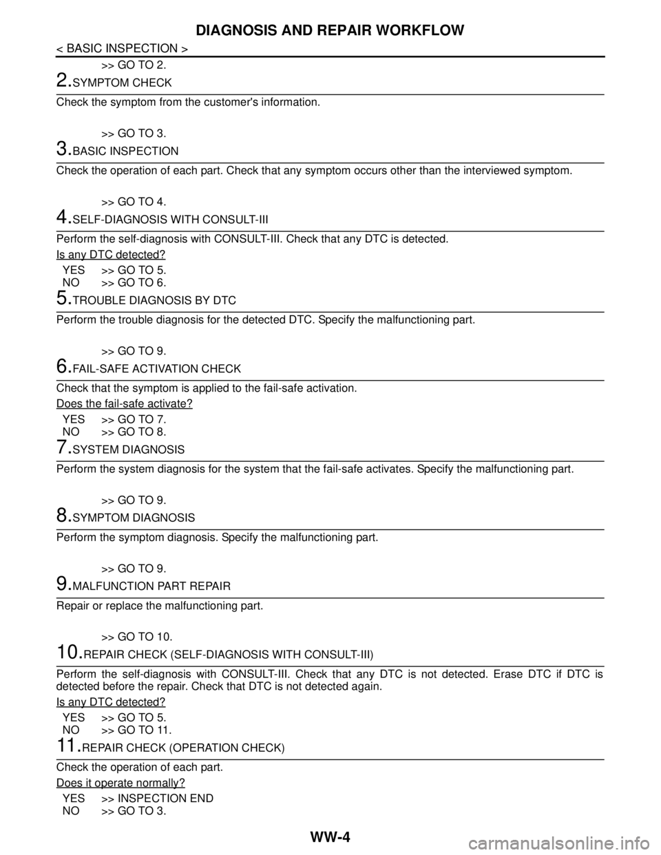
>> GO TO 2.
2.SYMPTOM CHECK
Check the symptom from the customer's information.
>> GO TO 3.
3.BASIC INSPECTION
Check the operation of each part. Check that any symptom occurs other than the interviewed symptom.
>> GO TO 4.
4.SELF-DIAGNOSIS WITH CONSULT-III
Perform the self-diagnosis with CONSULT-III. Check that any DTC is detected.
Is any DTC detected?
YES >> GO TO 5.
NO >> GO TO 6.
5.TROUBLE DIAGNOSIS BY DTC
Perform the trouble diagnosis for the detected DTC. Specify the malfunctioning part.
>> GO TO 9.
6.FAIL-SAFE ACTIVATION CHECK
Check that the symptom is applied to the fail-safe activation.
Does the fail-safe activate?
YES >> GO TO 7.
NO >> GO TO 8.
7.SYSTEM DIAGNOSIS
Perform the system diagnosis for the system that the fail-safe activates. Specify the malfunctioning part.
>> GO TO 9.
8.SYMPTOM DIAGNOSIS
Perform the symptom diagnosis. Specify the malfunctioning part.
>> GO TO 9.
9.MALFUNCTION PART REPAIR
Repair or replace the malfunctioning part.
>> GO TO 10.
10.REPAIR CHECK (SELF-DIAGNOSIS WITH CONSULT-III)
Perform the self-diagnosis with CONSULT-III. Check that any DTC is not detected. Erase DTC if DTC is
detected before the repair. Check that DTC is not detected again.
Is any DTC detected?
YES >> GO TO 5.
NO >> GO TO 11.
11 .REPAIR CHECK (OPERATION CHECK)
Check the operation of each part.
Does it operate normally?
YES >> INSPECTION END
NO >> GO TO 3.
Page 5108 of 5121

WW-96
< PRECAUTION >
PRECAUTIONS
PRECAUTION
PRECAUTIONS
Precaution for Supplemental Restraint System (SRS) "AIR BAG" and "SEAT BELT
PRE-TENSIONER"
INFOID:0000000003761618
The Supplemental Restraint System such as “AIR BAG” and “SEAT BELT PRE-TENSIONER”, used along
with a front seat belt, helps to reduce the risk or severity of injury to the driver and front passenger for certain
types of collision. This system includes seat belt switch inputs and dual stage front air bag modules. The SRS
system uses the seat belt switches to determine the front air bag deployment, and may only deploy one front
air bag, depending on the severity of a collision and whether the front occupants are belted or unbelted.
Information necessary to service the system safely is included in the “SRS AIRBAG” and “SEAT BELT” of this
Service Manual.
WARNING:
To avoid rendering the SRS inoperative, which could increase the risk of personal injury or death in
the event of a collision which would result in air bag inflation, all maintenance must be performed by
an authorized NISSAN/INFINITI dealer.
Improper maintenance, including incorrect removal and installation of the SRS, can lead to personal
injury caused by unintentional activation of the system. For removal of Spiral Cable and Air Bag
Module, see the “SRS AIRBAG”.
Never use electrical test equipment on any circuit related to the SRS unless instructed to in this Ser-
vice Manual. SRS wiring harnesses can be identified by yellow and/or orange harnesses or harness
connectors.
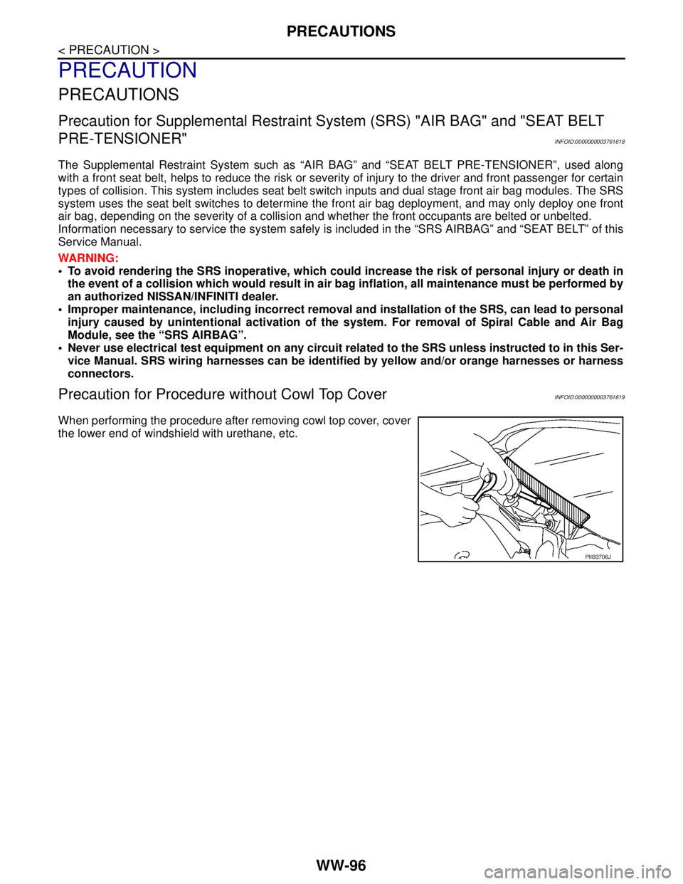
Precaution for Procedure without Cowl Top CoverINFOID:0000000003761619
When performing the procedure after removing cowl top cover, cover
the lower end of windshield with urethane, etc.
PIIB3706J