Page 3644 of 5121
PWC-14
< COMPONENT DIAGNOSIS >
POWER SUPPLY AND GROUND CIRCUIT
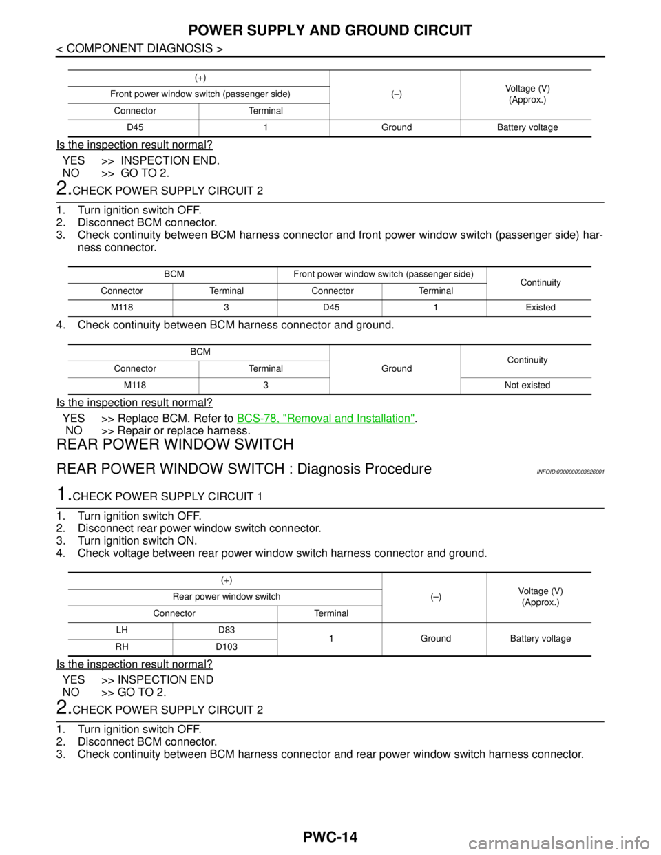
Is the inspection result normal?
YES >> INSPECTION END.
NO >> GO TO 2.
2.CHECK POWER SUPPLY CIRCUIT 2
1. Turn ignition switch OFF.
2. Disconnect BCM connector.
3. Check continuity between BCM harness connector and front power window switch (passenger side) har-
ness connector.
4. Check continuity between BCM harness connector and ground.
Is the inspection result normal?
YES >> Replace BCM. Refer to BCS-78, "Removal and Installation".
NO >> Repair or replace harness.
REAR POWER WINDOW SWITCH
REAR POWER WINDOW SWITCH : Diagnosis ProcedureINFOID:0000000003826001
1.CHECK POWER SUPPLY CIRCUIT 1
1. Turn ignition switch OFF.
2. Disconnect rear power window switch connector.
3. Turn ignition switch ON.
4. Check voltage between rear power window switch harness connector and ground.
Is the inspection result normal?
YES >> INSPECTION END
NO >> GO TO 2.
2.CHECK POWER SUPPLY CIRCUIT 2
1. Turn ignition switch OFF.
2. Disconnect BCM connector.
3. Check continuity between BCM harness connector and rear power window switch harness connector.
(+)
(–)Voltage (V)
(Approx.) Front power window switch (passenger side)
Connector Terminal
D45 1 Ground Battery voltage
BCM Front power window switch (passenger side)
Continuity
Connector Terminal Connector Terminal
M118 3 D45 1 Existed
BCM
GroundContinuity
Connector Terminal
M118 3 Not existed
(+)
(–)Voltage (V)
(Approx.) Rear power window switch
Connector Terminal
LH D83
1 Ground Battery voltage
RH D103
Page 3645 of 5121
POWER SUPPLY AND GROUND CIRCUIT
PWC-15
< COMPONENT DIAGNOSIS >
C
D
E
F
G
H
I
J
L
MA
B
PWC
N
O
P
4. Check continuity between BCM harness connector and ground.
Is the inspection result normal?
YES >> Replace BCM. Refer to BCS-78, "Removal and Installation".
NO >> Repair or replace harness.
BCM Rear power window switch
Continuity
Connector Terminal Connector Terminal
M118 3LH D83
1 Existed
RH D103
BCM
GroundContinuity
Connector Terminal
M118 3 Not existed
Page 3646 of 5121
PWC-16
< COMPONENT DIAGNOSIS >
FRONT POWER WINDOW SWITCH (PASSENGER SIDE)
FRONT POWER WINDOW SWITCH (PASSENGER SIDE)
DescriptionINFOID:0000000003826002
Front power window motor (passenger side) will be operated if front power window switch (passenger side) is
operated.
Component Function CheckINFOID:0000000003826003
1. CHECK FRONT POWER WINDOW SWITCH (PASSENGER SIDE) FUNCTION
Check front power window motor (passenger side) operation with front power window switch (passenger side).
Is the inspection result normal?
YES >> Front power window switch (passenger side) is OK.
NO >> Refer to PWC-16, "
Diagnosis Procedure".
Diagnosis ProcedureINFOID:0000000003826004
1.CHECK FRONT POWER WINDOW SWITCH (PASSENGER SIDE) INPUT SIGNAL
1. Turn ignition switch OFF.
2. Disconnect front power window switch (passenger side) connector.
3. Turn ignition switch ON.
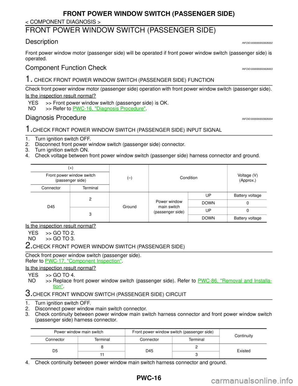
4. Check voltage between front power window switch (passenger side) harness connector and ground.
Is the inspection result normal?
YES >> GO TO 2.
NO >> GO TO 3.
2.CHECK FRONT POWER WINDOW SWITCH (PASSENGER SIDE)
Check front power window switch (passenger side).
Refer to PWC-17, "
Component Inspection".
Is the inspection result normal?
YES >> GO TO 4.
NO >> Replace front power window switch (passenger side). Refer to PWC-86, "
Removal and Installa-
tion".
3.CHECK FRONT WINDOW SWITCH (PASSENGER SIDE) CIRCUIT
1. Turn ignition switch OFF.
2. Disconnect power window main switch connector.
3. Check continuity between power window main switch harness connector and front power window switch
(passenger side) harness connector.
4. Check continuity between power window main switch harness connector and ground.
(+)
(–) ConditionVoltage (V)
(Approx.) Front power window switch
(passenger side)
Connector Terminal
D452
GroundPower window
main switch
(passenger side)UP Battery voltage
DOWN 0
3UP 0
DOWN Battery voltage
Power window main switch Front power window switch (passenger side)
Continuity
Connector Terminal Connector Terminal
D58
D452
Existed
11 3
Page 3647 of 5121
FRONT POWER WINDOW SWITCH (PASSENGER SIDE)
PWC-17
< COMPONENT DIAGNOSIS >
C
D
E
F
G
H
I
J
L
MA
B
PWC
N
O
P
Is the inspection result normal?
YES >> Replace power window main switch. Refer to PWC-85, "Removal and Installation".
NO >> Repair or replace harness.
4.CHECK INTERMITTENT INCIDENT
Refer to GI-35, "
Intermittent Incident".
>> INSPECTION END
Component InspectionINFOID:0000000003826005
1.CHECK FRONT POWER WINDOW SWITCH (PASSENGER SIDE)
1. Turn ignition OFF.
2. Disconnect front power window switch (passenger side) connector.
3. Check front power window switch (passenger side).
Is the inspection result normal?
YES >> INSPECTION END
NO >> Replace front power window switch (passenger side). Refer to PWC-86, "
Removal and Installa-
tion".
Power window main switch
GroundContinuity
Connector Terminal
D58
Not existed
11
Front power window
switch (passenger side)Te r m i n a lFront power window
switch conditionContinuity
D4515
UP
Existed 34
34
NEUTRAL
25
14
DOWN
25
Page 3648 of 5121
PWC-18
< COMPONENT DIAGNOSIS >
REAR POWER WINDOW SWITCH
REAR POWER WINDOW SWITCH
DescriptionINFOID:0000000003826006
Rear power window motor will be operated if rear power window switch is operated.
Component Function CheckINFOID:0000000003826007
1. CHECK REAR POWER WINDOW SWITCH FUNCTION
Check rear power window motor operation with rear power window switch.
Is the inspection result normal?
YES >> Rear power window switch is OK.
NO >> Refer to PWC-18, "
Diagnosis Procedure".
Diagnosis ProcedureINFOID:0000000003826008
1.CHECK REAR POWER WINDOW SWITCH INPUT SIGNAL
1. Turn ignition switch OFF.
2. Disconnect rear power window switch connector.
3. Turn ignition switch ON.
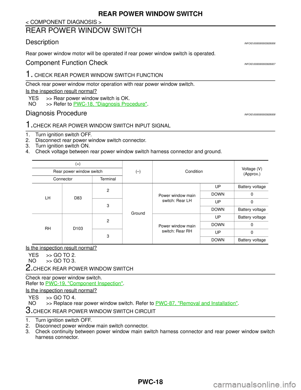
4. Check voltage between rear power window switch harness connector and ground.
Is the inspection result normal?
YES >> GO TO 2.
NO >> GO TO 3.
2.CHECK REAR POWER WINDOW SWITCH
Check rear power window switch.
Refer to PWC-19, "
Component Inspection".
Is the inspection result normal?
YES >> GO TO 4.
NO >> Replace rear power window switch. Refer to PWC-87, "
Removal and Installation".
3.CHECK REAR POWER WINDOW SWITCH CIRCUIT
1. Turn ignition switch OFF.
2. Disconnect power window main switch connector.
3. Check continuity between power window main switch harness connector and rear power window switch
harness connector.
(+)
(–) ConditionVoltage (V)
(Approx.) Rear power window switch
Connector Terminal
LH D832
GroundPower window main
switch: Rear LHUP Battery voltage
DOWN 0
3UP 0
DOWN Battery voltage
RH D1032
Power window main
switch: Rear RHUP Battery voltage
DOWN 0
3UP 0
DOWN Battery voltage
Page 3649 of 5121
REAR POWER WINDOW SWITCH
PWC-19
< COMPONENT DIAGNOSIS >
C
D
E
F
G
H
I
J
L
MA
B
PWC
N
O
P
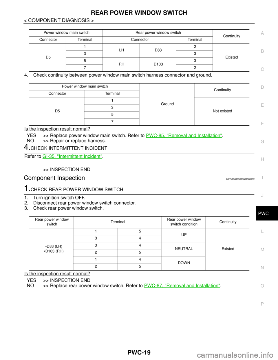
4. Check continuity between power window main switch harness connector and ground.
Is the inspection result normal?
YES >> Replace power window main switch. Refer to PWC-85, "Removal and Installation".
NO >> Repair or replace harness.
4.CHECK INTERMITTENT INCIDENT
Refer to GI-35, "
Intermittent Incident".
>> INSPECTION END
Component InspectionINFOID:0000000003826009
1.CHECK REAR POWER WINDOW SWITCH
1. Turn ignition switch OFF.
2. Disconnect rear power window switch connector.
3. Check rear power window switch.
Is the inspection result normal?
YES >> INSPECTION END
NO >> Replace rear power window switch. Refer to PWC-87, "
Removal and Installation".
Power window main switchRear power window switch
Continuity
Connector Terminal Connector Terminal
D51
LH D832
Existed 33
5
RH D1033
72
Power window main switch
GroundContinuity
Connector Terminal
D51
Not existed 3
5
7
Rear power window
switchTe r m i n a lRear power window
switch conditionContinuity
D83 (LH)
D103 (RH)15
UP
Existed 34
34
NEUTRAL
25
14
DOWN
25
Page 3650 of 5121
PWC-20
< COMPONENT DIAGNOSIS >
POWER WINDOW MOTOR
POWER WINDOW MOTOR
DRIVER SIDE
DRIVER SIDE : DescriptionINFOID:0000000003826010
Door glass moves UP/DOWN by receiving the signal from power window main switch.
DRIVER SIDE : Component Function CheckINFOID:0000000003826011
1. CHECK FRONT POWER WINDOW MOTOR (DRIVER SIDE) OPERATION
Check front power window motor (driver side) operation with power window main switch.
Is the inspection result normal?
YES >> Front power window motor (driver side) is OK.
NO >> Refer to PWC-20, "
DRIVER SIDE : Diagnosis Procedure".
DRIVER SIDE : Diagnosis ProcedureINFOID:0000000003826012
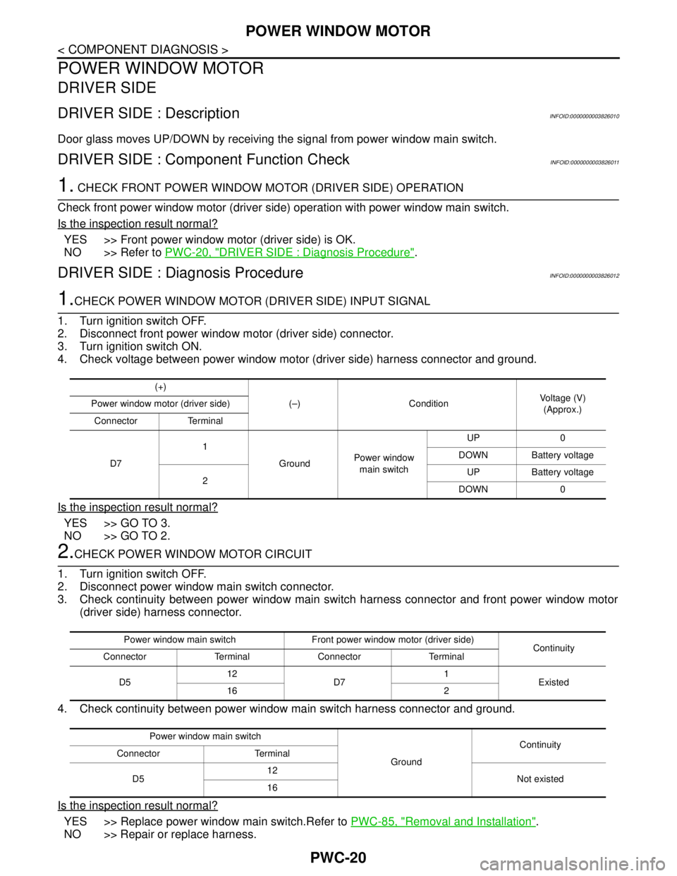
1.CHECK POWER WINDOW MOTOR (DRIVER SIDE) INPUT SIGNAL
1. Turn ignition switch OFF.
2. Disconnect front power window motor (driver side) connector.
3. Turn ignition switch ON.
4. Check voltage between power window motor (driver side) harness connector and ground.
Is the inspection result normal?
YES >> GO TO 3.
NO >> GO TO 2.
2.CHECK POWER WINDOW MOTOR CIRCUIT
1. Turn ignition switch OFF.
2. Disconnect power window main switch connector.
3. Check continuity between power window main switch harness connector and front power window motor
(driver side) harness connector.
4. Check continuity between power window main switch harness connector and ground.
Is the inspection result normal?
YES >> Replace power window main switch.Refer to PWC-85, "Removal and Installation".
NO >> Repair or replace harness.
(+)
(–) ConditionVoltage (V)
(Approx.) Power window motor (driver side)
Connector Terminal
D71
GroundPower window
main switchUP 0
DOWN Battery voltage
2UP Battery voltage
DOWN 0
Power window main switch Front power window motor (driver side)
Continuity
Connector Terminal Connector Terminal
D512
D71
Existed
16 2
Power window main switch
GroundContinuity
Connector Terminal
D512
Not existed
16
Page 3651 of 5121
POWER WINDOW MOTOR
PWC-21
< COMPONENT DIAGNOSIS >
C
D
E
F
G
H
I
J
L
MA
B
PWC
N
O
P
3.CHECK FRONT POWER WINDOW MOTOR (DRIVER SIDE)
Check front power window motor (driver side).
Refer to PWC-21, "
DRIVER SIDE : Component Inspection".
Is the inspection result normal?
YES >> GO TO 4.
NO >> Replace power window motor (driver side). Refer to GW-20, "
Removal and Installation".
4.CHECK INTERMITTENT INCIDENT
Refer to GI-35, "
Intermittent Incident".
>> INSPECTION END
DRIVER SIDE : Component InspectionINFOID:0000000003826013
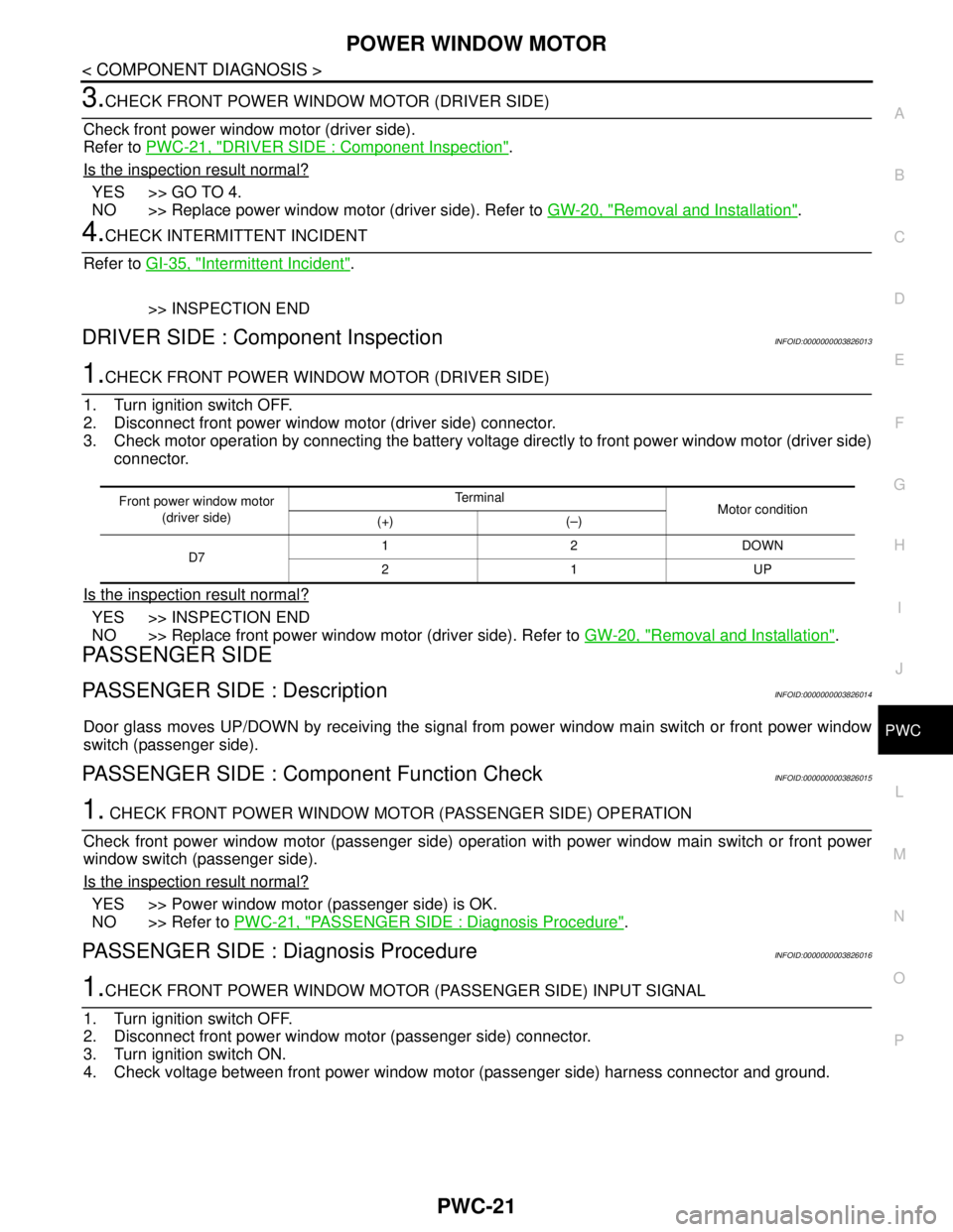
1.CHECK FRONT POWER WINDOW MOTOR (DRIVER SIDE)
1. Turn ignition switch OFF.
2. Disconnect front power window motor (driver side) connector.
3. Check motor operation by connecting the battery voltage directly to front power window motor (driver side)
connector.
Is the inspection result normal?
YES >> INSPECTION END
NO >> Replace front power window motor (driver side). Refer to GW-20, "
Removal and Installation".
PASSENGER SIDE
PASSENGER SIDE : DescriptionINFOID:0000000003826014
Door glass moves UP/DOWN by receiving the signal from power window main switch or front power window
switch (passenger side).
PASSENGER SIDE : Component Function CheckINFOID:0000000003826015
1. CHECK FRONT POWER WINDOW MOTOR (PASSENGER SIDE) OPERATION
Check front power window motor (passenger side) operation with power window main switch or front power
window switch (passenger side).
Is the inspection result normal?
YES >> Power window motor (passenger side) is OK.
NO >> Refer to PWC-21, "
PASSENGER SIDE : Diagnosis Procedure".
PASSENGER SIDE : Diagnosis ProcedureINFOID:0000000003826016
1.CHECK FRONT POWER WINDOW MOTOR (PASSENGER SIDE) INPUT SIGNAL
1. Turn ignition switch OFF.
2. Disconnect front power window motor (passenger side) connector.
3. Turn ignition switch ON.
4. Check voltage between front power window motor (passenger side) harness connector and ground.
Front power window motor
(driver side)Te r m i n a l
Motor condition
(+) (–)
D712DOWN
21UP