Page 2952 of 5121

BCM (BODY CONTROL MODULE)
INL-73
< ECU DIAGNOSIS >
C
D
E
F
G
H
I
J
K
MA
B
INL
N
O
P
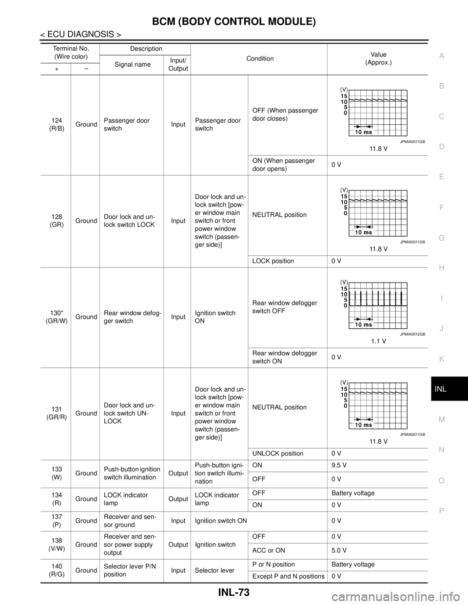
124
(R/B)GroundPassenger door
switchInputPassenger door
switchOFF (When passenger
door closes)
11.8 V
ON (When passenger
door opens)0 V
128
(GR)GroundDoor lock and un-
lock switch LOCKInputDoor lock and un-
lock switch [pow-
er window main
switch or front
power window
switch (passen-
ger side)]NEUTRAL position
11.8 V
LOCK position 0 V
130*
(GR/W)GroundRear window defog-
ger switchInputIgnition switch
ONRear window defogger
switch OFF
1.1 V
Rear window defogger
switch ON0 V
131
(GR/R)GroundDoor lock and un-
lock switch UN-
LOCKInputDoor lock and un-
lock switch [pow-
er window main
switch or front
power window
switch (passen-
ger side)]NEUTRAL position
11.8 V
UNLOCK position 0 V
133
(W)GroundPush-button ignition
switch illuminationOutputPush-button igni-
tion switch illumi-
nationON 9.5 V
OFF 0 V
134
(R)GroundLOCK indicator
lampOutputLOCK indicator
lampOFF Battery voltage
ON 0 V
137
(P)GroundReceiver and sen-
sor groundInput Ignition switch ON 0 V
138
(V/W)GroundReceiver and sen-
sor power supply
outputOutput Ignition switchOFF 0 V
ACC or ON 5.0 V
140
(R/G)GroundSelector lever P/N
positionInput Selector leverP or N position Battery voltage
Except P and N positions 0 V Te r m i n a l N o .
(Wire color)Description
ConditionVa l u e
(Approx.)
Signal nameInput/
Output +–
JPMIA0011GB
JPMIA0011GB
JPMIA0012GB
JPMIA0011GB
Page 2954 of 5121
BCM (BODY CONTROL MODULE)
INL-75
< ECU DIAGNOSIS >
C
D
E
F
G
H
I
J
K
MA
B
INL
N
O
PNOTE:
*: Without BOSE audio system145
(LG/R)GroundCombination switch
OUTPUT 3OutputCombination
switch
(Wiper intermit-
tent dial 4)All switch OFF 0 V
Front wiper switch INT
10.7 V Front wiper switch LO
Lighting switch AUTO
Rear fog lamp switch ON
146
(G/Y)GroundCombination switch
OUTPUT 4OutputCombination
switch
(Wiper intermit-
tent dial 4)All switch OFF 0 V
Front fog lamp switch ON
10.7 V Lighting switch 2ND
Lighting switch PASS
Turn signal switch LH
150
(SB)Ground Driver door switch Input Driver door switchOFF (When driver door
closes)
11.8 V
ON (When driver door
opens)0 V
151
(G/R)GroundRear window defog-
ger relayOutputRear window de-
foggerActive 0 V
Not activated Battery voltage Te r m i n a l N o .
(Wire color)Description
ConditionVa l u e
(Approx.)
Signal nameInput/
Output +–
JPMIA0034GB
JPMIA0035GB
JPMIA0011GB
Page 3007 of 5121
INT-30
< ON-VEHICLE REPAIR >
FRONT DOOR FINISHER
ON-VEHICLE REPAIR
FRONT DOOR FINISHER
DRIVER SIDE
DRIVER SIDE : Exploded ViewINFOID:0000000003819216
DRIVER SIDE : Removal and InstallationINFOID:0000000003819217
CAUTION:
Wrap the tip of flat-bladed screwdriver with a cloth before remove.
REMOVAL
1. Front door panel 2. Front door inside handle 3. Power window switch finisher
4. Front door finisher 5. Inside handle escutcheon 6. Step lamp
7. Cap 8. Seat memory switch finisher 9. Power window switch
10. Door mirror remote control switch
: Clip
: Pawl
: Metal clip
JMJIA1798ZZ
Page 3008 of 5121
FRONT DOOR FINISHER
INT-31
< ON-VEHICLE REPAIR >
C
D
E
F
G
H
I
K
L
MA
B
INT
N
O
P
1. Fully open door window.
2. Remove inside handle escutcheon (1) with a flat-bladed screw-
driver (A) wrapped in a tape as shown in the figure.
3. Remove screw (A) located on the back side of inside handle
escutcheon.
4. Remove the cap and front door finisher fixing bolt as shown in
the figure with tool (A).
5. Remove step lamp and then disconnect the harness connector. Refer to INL-95, "
Removal and Installa-
tion".
6. Insert a remover tool (A) between the door finisher and door
panel to disengage the clips and pawl.
CAUTION:
Insert a remover tool (A) into the part shown in the figure.
(Between the clips and the door panel)
: Pawl
JMJIA1755ZZ
JMJIA1757ZZ
JMJIA1759ZZ
: Clip
: Metal clip
JMJIA1760ZZ
Page 3009 of 5121
INT-32
< ON-VEHICLE REPAIR >
FRONT DOOR FINISHER
7. Disconnect lock knob cable (1), inside handle cable (2), power
window switch finisher harness connectors (B) and seat memory
switch harness connector (A).
8. Remove front door finisher.
9. Remove the following parts after removing front door finisher.
Front door inside handle. Refer to DLK-223, "
INSIDE HANDLE : Removal and Installation".
Seat memory switch. Refer to ADP-137, "
Removal and Installation".
Disengage power window switch finisher (1) pawls as shown by the figure by pressing them toward the
arrow, then remove the power window switch finisher (1) from the door finisher (2).
INSTALLATION
Install in the reverse order of removal.
CAUTION:
When installing door finisher, check that clips are securely fitted in panel holes on body, and then
press them in.
PASSENGER SIDE
JMJIA1761ZZ
JMJIA1954ZZ
Page 3010 of 5121
FRONT DOOR FINISHER
INT-33
< ON-VEHICLE REPAIR >
C
D
E
F
G
H
I
K
L
MA
B
INT
N
O
P
PASSENGER SIDE : Exploded ViewINFOID:0000000003819218
PASSENGER SIDE : Removal and InstallationINFOID:0000000003819219
CAUTION:
Wrap the tip of flat-bladed screwdriver with a cloth before remove.
REMOVAL
1. Fully open door window.
1. Front door panel 2. Front door inside handle 3. Front door finisher
4. Cap 5. Step lamp 6. Front door grip
7. Front door grip cover 8. Inside handle escutcheon 9. Power window switch finisher
10. Power window switch
: Clip
: Pawl
: Metal clip
JMJIA1799ZZ
Page 3012 of 5121

FRONT DOOR FINISHER
INT-35
< ON-VEHICLE REPAIR >
C
D
E
F
G
H
I
K
L
MA
B
INT
N
O
P
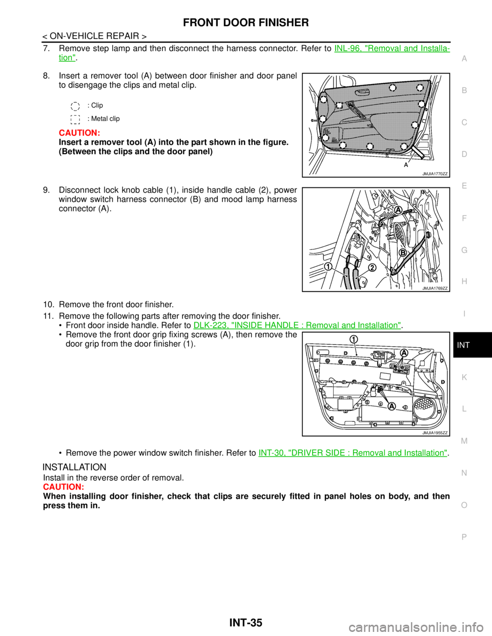
7. Remove step lamp and then disconnect the harness connector. Refer to INL-96, "Removal and Installa-
tion".
8. Insert a remover tool (A) between door finisher and door panel
to disengage the clips and metal clip.
CAUTION:
Insert a remover tool (A) into the part shown in the figure.
(Between the clips and the door panel)
9. Disconnect lock knob cable (1), inside handle cable (2), power
window switch harness connector (B) and mood lamp harness
connector (A).
10. Remove the front door finisher.
11. Remove the following parts after removing the door finisher.
Front door inside handle. Refer to DLK-223, "
INSIDE HANDLE : Removal and Installation".
Remove the front door grip fixing screws (A), then remove the
door grip from the door finisher (1).
Remove the power window switch finisher. Refer to INT-30, "
DRIVER SIDE : Removal and Installation".
INSTALLATION
Install in the reverse order of removal.
CAUTION:
When installing door finisher, check that clips are securely fitted in panel holes on body, and then
press them in.
: Clip
: Metal clip
JMJIA1770ZZ
JMJIA1769ZZ
JMJIA1955ZZ
Page 3013 of 5121
INT-36
< ON-VEHICLE REPAIR >
REAR DOOR FINISHER
REAR DOOR FINISHER
Exploded ViewINFOID:0000000003819220
Removal and InstallationINFOID:0000000003819221
CAUTION:
Wrap the tip of flat-bladed screwdriver with a cloth before remove.
REMOVAL
1. Fully open door window.
1. Rear door panel 2. Rear door inside handle 3. Rear door power window switch fin-
isher
4. Rear door finisher 5. Rear door grip cover 6. Rear door grip
7. Inside handle escutcheon 8. Cap 9. Rear door power window switch
: Clip
: Pawl
JMJIA1800ZZ