Page 3015 of 5121

INT-38
< ON-VEHICLE REPAIR >
REAR DOOR FINISHER
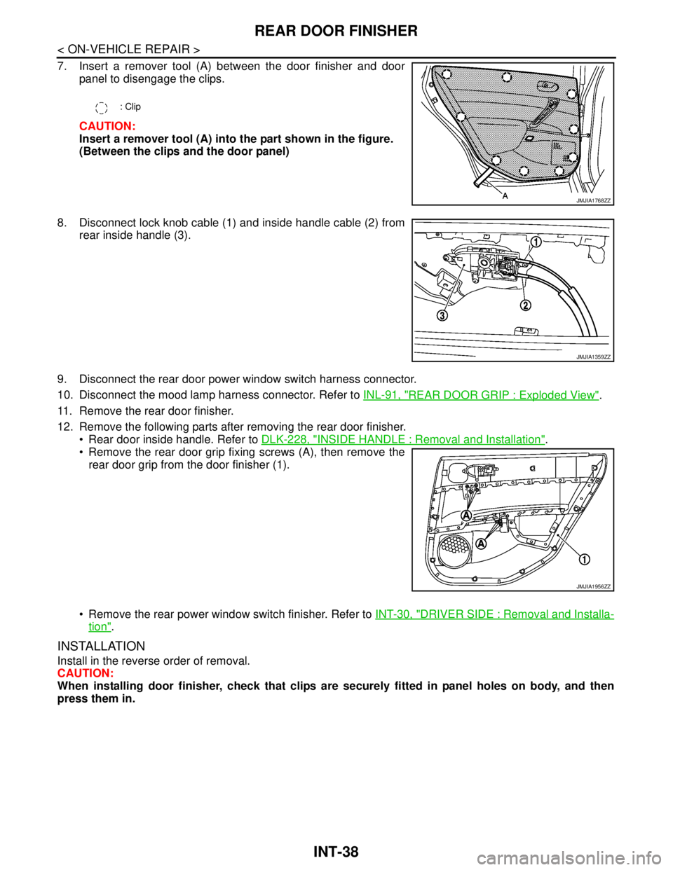
7. Insert a remover tool (A) between the door finisher and door
panel to disengage the clips.
CAUTION:
Insert a remover tool (A) into the part shown in the figure.
(Between the clips and the door panel)
8. Disconnect lock knob cable (1) and inside handle cable (2) from
rear inside handle (3).
9. Disconnect the rear door power window switch harness connector.
10. Disconnect the mood lamp harness connector. Refer to INL-91, "
REAR DOOR GRIP : Exploded View".
11. Remove the rear door finisher.
12. Remove the following parts after removing the rear door finisher.
Rear door inside handle. Refer to DLK-228, "
INSIDE HANDLE : Removal and Installation".
Remove the rear door grip fixing screws (A), then remove the
rear door grip from the door finisher (1).
Remove the rear power window switch finisher. Refer to INT-30, "
DRIVER SIDE : Removal and Installa-
tion".
INSTALLATION
Install in the reverse order of removal.
CAUTION:
When installing door finisher, check that clips are securely fitted in panel holes on body, and then
press them in.
: Clip
JMJIA1768ZZ
JMJIA1359ZZ
JMJIA1956ZZ
Page 3090 of 5121
![NISSAN TEANA 2008 Service Manual LAN
CAN COMMUNICATION SYSTEM
LAN-23
< FUNCTION DIAGNOSIS >[CAN]
C
D
E
F
G
H
I
J
K
L B A
O
P N
NOTE:
Refer to LAN-19, "
Abbreviation List" for the abbreviations of the connecting units.
T: Transmit R: NISSAN TEANA 2008 Service Manual LAN
CAN COMMUNICATION SYSTEM
LAN-23
< FUNCTION DIAGNOSIS >[CAN]
C
D
E
F
G
H
I
J
K
L B A
O
P N
NOTE:
Refer to LAN-19, "
Abbreviation List" for the abbreviations of the connecting units.
T: Transmit R:](/manual-img/5/57391/w960_57391-3089.png)
LAN
CAN COMMUNICATION SYSTEM
LAN-23
< FUNCTION DIAGNOSIS >[CAN]
C
D
E
F
G
H
I
J
K
L B A
O
P N
NOTE:
Refer to LAN-19, "
Abbreviation List" for the abbreviations of the connecting units.
T: Transmit R: Receive
Signal name/Connecting unitECM
ADP
AV
HVAC
M&A
STRG
BCM
ABS
TCM
IPDM-E
A/C compressor request signal TR
Accelerator pedal position signal T R R
ASCD CRUISE indicator signal T R
ASCD operation signal T R
ASCD SET indicator signal T R
Closed throttle position signal T R
Cooling fan speed request signal TR
Engine and CVT integrated control signalTR
RT
Engine coolant temperature signal T R
Engine speed signal T R R R
Engine status signal T R R
Fuel consumption monitor signal T R
Malfunctioning indicator lamp signal T R
Power generation command value signal TR
System setting signalTR
RT R
RT
Rear window defogger switch signal T R
A/C switch signal R T T
Blower fan motor switch signal R T T
Distance to empty signal R T
Fuel level low warning signal R T
Sleep-ready signalTR
RT
Sport mode switch signal T R
Vehicle speed signalRR T R RR
RR R R T
Wake up signal T R
Steering angle sensor signal T R
Buzzer output signal R T
Door switch signal R R R T R
Door unlock signal R T
Front fog light request signal R T R
Front wiper request signalTR
Headlamp washer request signal T R
High beam request signal R T R
Hood switch signalTR
Horn reminder signalTR
Ignition switch ON signalTR
RT
Page 3091 of 5121
![NISSAN TEANA 2008 Service Manual LAN-24
< FUNCTION DIAGNOSIS >[CAN]
CAN COMMUNICATION SYSTEM
Ignition switch signal R T
Interlock/PNP switch signalTR
RT
Key ID signal R T
Key switch signal R T
Key warning lamp signal R T
Low beam req NISSAN TEANA 2008 Service Manual LAN-24
< FUNCTION DIAGNOSIS >[CAN]
CAN COMMUNICATION SYSTEM
Ignition switch signal R T
Interlock/PNP switch signalTR
RT
Key ID signal R T
Key switch signal R T
Key warning lamp signal R T
Low beam req](/manual-img/5/57391/w960_57391-3090.png)
LAN-24
< FUNCTION DIAGNOSIS >[CAN]
CAN COMMUNICATION SYSTEM
Ignition switch signal R T
Interlock/PNP switch signalTR
RT
Key ID signal R T
Key switch signal R T
Key warning lamp signal R T
Low beam request signalTR
Meter display signal R T
Oil pressure switch signalRT
RT
Position light request signal R T R
Rear fog lamp status signal R T
Rear window defogger control signalTR
RR R T
Sleep wake up signal R R T R
Starter control relay signalTR
Starter relay status signalRT
TR
Starting mode signal R T
Steering lock relay signalTR
RT
Stop lamp switch signalTR
Theft warning horn request signal T R
Trunk switch signal R R T
ABS operation signal TR
ABS warning lamp signal R T
Brake warning lamp signal R T
SLIP indicator lamp signal R T
VDC OFF indicator lamp signal R T
CVT position indicator signal R R R T
CVT self-diagnosis signal R T
Input shaft revolution signal R T
N range signalRT
Output shaft revolution signal R T
P range signal R R R T
Shift position signal R R T
Sport mode indicator signal R T
A/C compressor feedback signal R T
Control device (detention switch) signal R R T
Front wiper stop position signal R T
High beam status signal RT
Low beam status signal RT Signal name/Connecting unit
ECM
ADP
AV
HVAC
M&A
STRG
BCM
ABS
TCM
IPDM-E
Page 3254 of 5121
DOOR MIRROR REMOTE CONTROL SWITCH
MIR-21
< ON-VEHICLE REPAIR >
C
D
E
F
G
H
I
J
K
MA
B
MIR
N
O
P
DOOR MIRROR REMOTE CONTROL SWITCH
Exploded ViewINFOID:0000000003815752
Refer to INT-30, "DRIVER SIDE : Exploded View".
Removal and InstallationINFOID:0000000003815753
REMOVAL
1. Remove the power window main switch finisher. Refer to PWC-85, "Exploded View".
2. Remove door mirror remote control switch (1) from power win-
dow main switch finisher (2) using screwdriver (A).
INSTALLATION
Install in the reverse order of removal.
: Pawl
JMLIA0130ZZ
Page 3323 of 5121

MWI
BCM (BODY CONTROL MODULE)
MWI-69
< ECU DIAGNOSIS >
C
D
E
F
G
H
I
J
K
L
MB A
O
P
DOOR SW-BKNOTE:
The item is indicated, but not monitored. Off
CDL LOCK SWOther than power door lock switch LOCK Off
Power door lock switch LOCK On
CDL UNLOCK SWOther than power door lock switch UNLOCK Off
Power door lock switch UNLOCK On
KEY CYL LK-SWNOTE:
The item is indicated, but not monitored. Off
KEY CYL UN-SWNOTE:
The item is indicated, but not monitored. Off
KEY CYL SW-TRNOTE:
The item is indicated, but not monitored. Off
HAZARD SWHazard switch is OFF Off
Hazard switch is ON On
REAR DEF SW
NOTE:
At model with BOSE au-
dio system this item is in-
dicated, but is not
monitored.Rear window defogger switch is OFF Off
Rear window defogger switch is ON On
TR CANCEL SWNOTE:
The item is indicated, but not monitored. Off
TR/BD OPEN SWTrunk lid opener switch OFF Off
While the trunk lid opener switch is turned ON On
TRNK/HAT MNTRTrunk lid closed Off
Trunk lid opened On
RKE-LOCKLOCK button of the key is not pressed Off
LOCK button of the key is pressed On
RKE-UNLOCKUNLOCK button of the key is not pressed Off
UNLOCK button of the key is pressed On
RKE-TR/BDTRUNK OPEN button of the key is not pressed Off
TRUNK OPEN button of the key is pressed On
RKE-PANICNOTE:
The item is indicated, but not monitored. Off
RKE-P/W OPENNOTE:
The item is indicated, but not monitored. Off
RKE-MODE CHGLOCK/UNLOCK button of the key is not pressed and held simulta-
neouslyOff
LOCK/UNLOCK button of the key is pressed and held simulta-
neouslyOn
OPTICAL SENSORBright outside of the vehicle Close to 5 V
Dark outside of the vehicle Close to 0 V
REQ SW -DRDriver door request switch is not pressed Off
Driver door request switch is pressed On
REQ SW -ASPassenger door request switch is not pressed Off
Passenger door request switch is pressed On
REQ SW -RRNOTE:
The item is indicated, but not monitored. Off Monitor Item Condition Value/Status
Page 3342 of 5121

MWI-88
< ECU DIAGNOSIS >
BCM (BODY CONTROL MODULE)
124
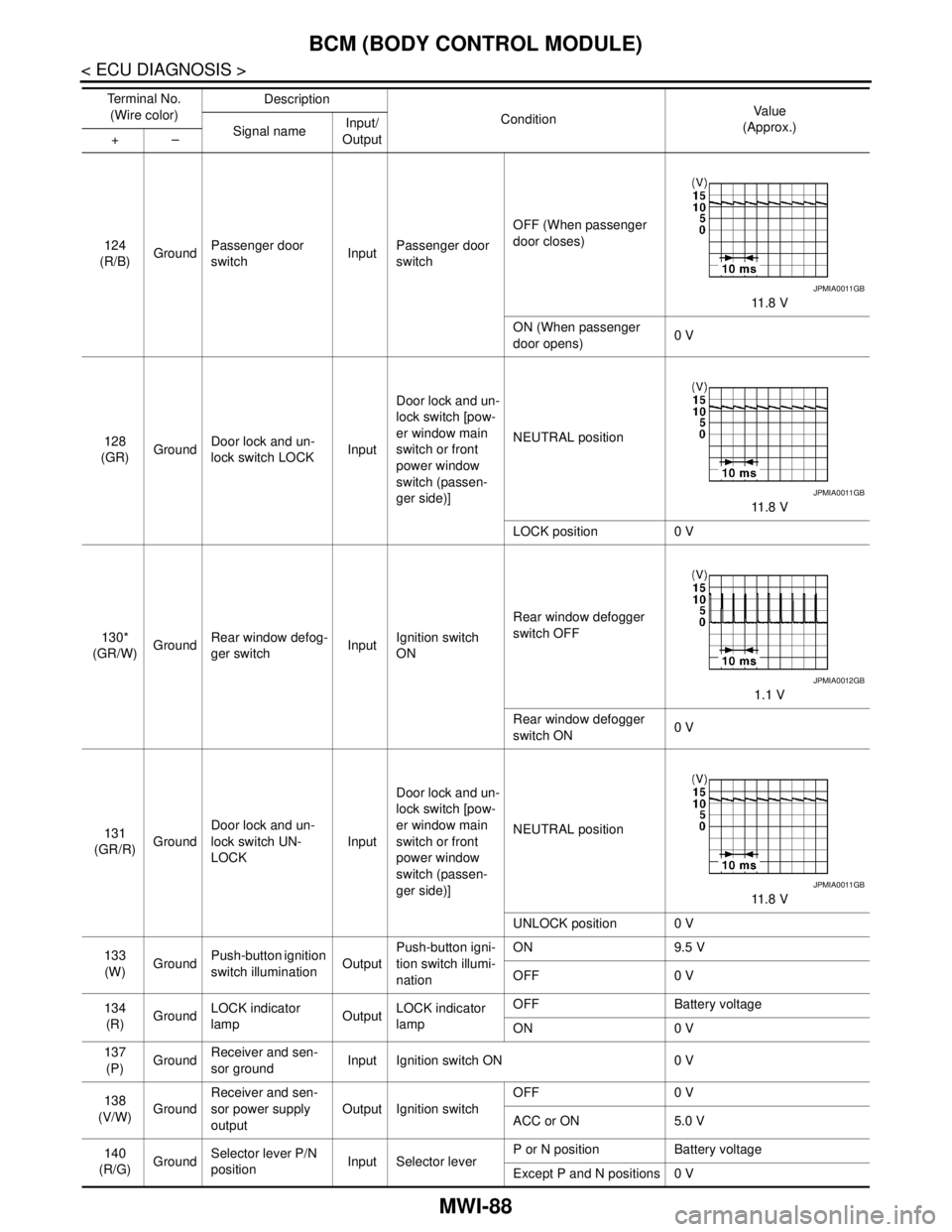
(R/B)GroundPassenger door
switchInputPassenger door
switchOFF (When passenger
door closes)
11 . 8 V
ON (When passenger
door opens)0 V
128
(GR)GroundDoor lock and un-
lock switch LOCKInputDoor lock and un-
lock switch [pow-
er window main
switch or front
power window
switch (passen-
ger side)]NEUTRAL position
11 . 8 V
LOCK position 0 V
130*
(GR/W)GroundRear window defog-
ger switchInputIgnition switch
ONRear window defogger
switch OFF
1.1 V
Rear window defogger
switch ON0 V
131
(GR/R)GroundDoor lock and un-
lock switch UN-
LOCKInputDoor lock and un-
lock switch [pow-
er window main
switch or front
power window
switch (passen-
ger side)]NEUTRAL position
11 . 8 V
UNLOCK position 0 V
133
(W)GroundPush-button ignition
switch illuminationOutputPush-button igni-
tion switch illumi-
nationON 9.5 V
OFF 0 V
134
(R)GroundLOCK indicator
lampOutputLOCK indicator
lampOFF Battery voltage
ON 0 V
137
(P)GroundReceiver and sen-
sor groundInput Ignition switch ON 0 V
138
(V/W)GroundReceiver and sen-
sor power supply
outputOutput Ignition switchOFF 0 V
ACC or ON 5.0 V
140
(R/G)GroundSelector lever P/N
positionInput Selector leverP or N position Battery voltage
Except P and N positions 0 V Te r m i n a l N o .
(Wire color)Description
ConditionVa l u e
(Approx.)
Signal nameInput/
Output +–
JPMIA0011GB
JPMIA0011GB
JPMIA0012GB
JPMIA0011GB
Page 3344 of 5121
MWI-90
< ECU DIAGNOSIS >
BCM (BODY CONTROL MODULE)
NOTE:
*: Without BOSE audio system145
(LG/R)GroundCombination switch
OUTPUT 3OutputCombination
switch
(Wiper intermit-
tent dial 4)All switch OFF 0 V
Front wiper switch INT
10.7 V Front wiper switch LO
Lighting switch AUTO
Rear fog lamp switch ON
146
(G/Y)GroundCombination switch
OUTPUT 4OutputCombination
switch
(Wiper intermit-
tent dial 4)All switch OFF 0 V
Front fog lamp switch ON
10.7 V Lighting switch 2ND
Lighting switch PASS
Turn signal switch LH
150
(SB)Ground Driver door switch Input Driver door switchOFF (When driver door
closes)
11 . 8 V
ON (When driver door
opens)0 V
151
(G/R)GroundRear window defog-
ger relayOutputRear window de-
foggerActive 0 V
Not activated Battery voltage Te r m i n a l N o .
(Wire color)Description
ConditionVa l u e
(Approx.)
Signal nameInput/
Output +–
JPMIA0034GB
JPMIA0035GB
JPMIA0011GB
Page 3399 of 5121
PCS-8
< FUNCTION DIAGNOSIS >[IPDM E/R]
SIGNAL BUFFER SYSTEM
SIGNAL BUFFER SYSTEM
System DiagramINFOID:0000000003773261
NOTE:
*: With BOSE audio system
System DescriptionINFOID:0000000003773262
IPDM E/R reads the status of the oil pressure switch and transmits the oil pressure switch signal to BCM via
CAN communication. Refer to MWI-22, "
WARNING LAMPS/INDICATOR LAMPS : System Diagram".
IPDM E/R reads the status of the hood switch and transmits the hood switch signal to BCM via CAN commu-
nication. Refer to SEC-17, "
System Diagram".
IPDM E/R receives the rear window defogger control signal from BCM via CAN communication and trans-
mits it to ECM and AV control unit
* via CAN communication. Refer to DEF-4, "WITH AV CONTROL UNIT :
System Diagram" or DEF-6, "WITHOUT AV CONTROL UNIT : System Diagram".
NOTE:
*: With BOSE audio system
Component Parts LocationINFOID:0000000003773263
JPMIA1043GB
1. IPDM E/R
A. Engine room (LH)
JPMIA1037ZZ