Page 3663 of 5121

BCM (BODY CONTROL MODULE)
PWC-33
< ECU DIAGNOSIS >
C
D
E
F
G
H
I
J
L
MA
B
PWC
N
O
P
DOOR SW-RLRear LH door closed Off
Rear LH door opened On
DOOR SW-BKNOTE:
The item is indicated, but not monitored. Off
CDL LOCK SWOther than power door lock switch LOCK Off
Power door lock switch LOCK On
CDL UNLOCK SWOther than power door lock switch UNLOCK Off
Power door lock switch UNLOCK On
KEY CYL LK-SWNOTE:
The item is indicated, but not monitored. Off
KEY CYL UN-SWNOTE:
The item is indicated, but not monitored. Off
KEY CYL SW-TRNOTE:
The item is indicated, but not monitored. Off
HAZARD SWHazard switch is OFF Off
Hazard switch is ON On
REAR DEF SW
NOTE:
At model with BOSE au-
dio system this item is in-
dicated, but is not
monitored.Rear window defogger switch is OFF Off
Rear window defogger switch is ON On
TR CANCEL SWNOTE:
The item is indicated, but not monitored. Off
TR/BD OPEN SWTrunk lid opener switch OFF Off
While the trunk lid opener switch is turned ON On
TRNK/HAT MNTRTrunk lid closed Off
Trunk lid opened On
RKE-LOCKLOCK button of the key is not pressed Off
LOCK button of the key is pressed On
RKE-UNLOCKUNLOCK button of the key is not pressed Off
UNLOCK button of the key is pressed On
RKE-TR/BDTRUNK OPEN button of the key is not pressed Off
TRUNK OPEN button of the key is pressed On
RKE-PANICNOTE:
The item is indicated, but not monitored. Off
RKE-P/W OPENNOTE:
The item is indicated, but not monitored. Off
RKE-MODE CHGLOCK/UNLOCK button of the key is not pressed and held simulta-
neouslyOff
LOCK/UNLOCK button of the key is pressed and held simulta-
neouslyOn
OPTICAL SENSORBright outside of the vehicle Close to 5 V
Dark outside of the vehicle Close to 0 V
REQ SW -DRDriver door request switch is not pressed Off
Driver door request switch is pressed On
REQ SW -ASPassenger door request switch is not pressed Off
Passenger door request switch is pressed On Monitor Item Condition Value/Status
Page 3682 of 5121

PWC-52
< ECU DIAGNOSIS >
BCM (BODY CONTROL MODULE)
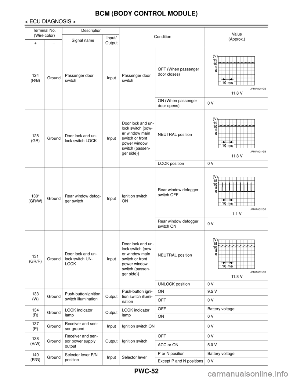
124
(R/B)GroundPassenger door
switchInputPassenger door
switchOFF (When passenger
door closes)
11 . 8 V
ON (When passenger
door opens)0 V
128
(GR)GroundDoor lock and un-
lock switch LOCKInputDoor lock and un-
lock switch [pow-
er window main
switch or front
power window
switch (passen-
ger side)]NEUTRAL position
11 . 8 V
LOCK position 0 V
130*
(GR/W)GroundRear window defog-
ger switchInputIgnition switch
ONRear window defogger
switch OFF
1.1 V
Rear window defogger
switch ON0 V
131
(GR/R)GroundDoor lock and un-
lock switch UN-
LOCKInputDoor lock and un-
lock switch [pow-
er window main
switch or front
power window
switch (passen-
ger side)]NEUTRAL position
11 . 8 V
UNLOCK position 0 V
133
(W)GroundPush-button ignition
switch illuminationOutputPush-button igni-
tion switch illumi-
nationON 9.5 V
OFF 0 V
134
(R)GroundLOCK indicator
lampOutputLOCK indicator
lampOFF Battery voltage
ON 0 V
137
(P)GroundReceiver and sen-
sor groundInput Ignition switch ON 0 V
138
(V/W)GroundReceiver and sen-
sor power supply
outputOutput Ignition switchOFF 0 V
ACC or ON 5.0 V
140
(R/G)GroundSelector lever P/N
positionInput Selector leverP or N position Battery voltage
Except P and N positions 0 V Te r m i n a l N o .
(Wire color)Description
ConditionVa l u e
(Approx.)
Signal nameInput/
Output +–
JPMIA0011GB
JPMIA0011GB
JPMIA0012GB
JPMIA0011GB
Page 3684 of 5121
PWC-54
< ECU DIAGNOSIS >
BCM (BODY CONTROL MODULE)
NOTE:
*: Without BOSE audio system145
(LG/R)GroundCombination switch
OUTPUT 3OutputCombination
switch
(Wiper intermit-
tent dial 4)All switch OFF 0 V
Front wiper switch INT
10.7 V Front wiper switch LO
Lighting switch AUTO
Rear fog lamp switch ON
146
(G/Y)GroundCombination switch
OUTPUT 4OutputCombination
switch
(Wiper intermit-
tent dial 4)All switch OFF 0 V
Front fog lamp switch ON
10.7 V Lighting switch 2ND
Lighting switch PASS
Turn signal switch LH
150
(SB)Ground Driver door switch Input Driver door switchOFF (When driver door
closes)
11 . 8 V
ON (When driver door
opens)0 V
151
(G/R)GroundRear window defog-
ger relayOutputRear window de-
foggerActive 0 V
Not activated Battery voltage Te r m i n a l N o .
(Wire color)Description
ConditionVa l u e
(Approx.)
Signal nameInput/
Output +–
JPMIA0034GB
JPMIA0035GB
JPMIA0011GB
Page 3696 of 5121

PWC-66
< ECU DIAGNOSIS >
POWER WINDOW MAIN SWITCH
POWER WINDOW MAIN SWITCH
Reference Value INFOID:0000000003826034
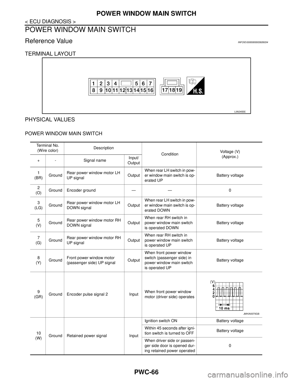
TERMINAL LAYOUT
PHYSICAL VALUES
POWER WINDOW MAIN SWITCH
LIIA2455E
Te r m i n a l N o .
(Wire color)Description
ConditionVoltage (V)
(Approx.)
+ - Signal name Input/
Output
1
(BR)GroundRear power window motor LH
UP signalOutputWhen rear LH switch in pow-
er window main switch is op-
erated UP Battery voltage
2
(O)Ground Encoder ground — — 0
3
(LG)GroundRear power window motor LH
DOWN signalOutputWhen rear LH switch in pow-
er window main switch is op-
erated DOWN Battery voltage
5
(V)GroundRear power window motor RH
DOWN signalOutputWhen rear RH switch in
power window main switch
is operated DOWN Battery voltage
7
(G)GroundRear power window motor RH
UP signalOutputWhen rear RH switch in
power window main switch
is operated UP Battery voltage
8
(Y)GroundFront power window motor
(passenger side) UP signalOutputWhen front power window
switch (passenger side) in
power window main switch
is operated UP Battery voltage
9
(GR)Ground Encoder pulse signal 2 InputWhen front power window
motor (driver side) operates
10
(W)Ground Retained power signal InputIgnition switch ON Battery voltage
Within 45 seconds after igni-
tion switch is turned to OFFBattery voltage
When driver side or passen-
ger side door is opened dur-
ing retained power operated0
JMKIA0070GB
Page 3697 of 5121
POWER WINDOW MAIN SWITCH
PWC-67
< ECU DIAGNOSIS >
C
D
E
F
G
H
I
J
L
MA
B
PWC
N
O
P
11
(B)GroundFront power window motor
(passenger side) DOWN signalOutputWhen front power window
switch (passenger side) in
power window main switch
is operated DOWN Battery voltage
12
(L)GroundFront power window motor
(driver side) DOWN signalOutputWhen power window main
switch is operated DOWN Battery voltage
13
(SB)Ground Encoder pulse signal 1 InputWhen front power window
motor (driver side) operates.
15
(W)Ground Encoder power supply Output Ignition switch ON Battery voltage
16
(R)GroundFront power window motor
(driver side) UP signalOutputWhen power window main
switch is operated UP Battery voltage
17
(B)Ground Ground — — 0
19
(P)Ground Battery power supply Input Ignition switch OFF Battery voltage Te r m i n a l N o .
(Wire color)Description
ConditionVoltage (V)
(Approx.)
+ - Signal name Input/
Output
JMKIA0070GB
Page 3698 of 5121
PWC-68
< ECU DIAGNOSIS >
POWER WINDOW MAIN SWITCH
Wiring Diagram - POWER WINDOW SYSTEM -
INFOID:0000000003940981
JCKWM1227GB
Page 3699 of 5121
POWER WINDOW MAIN SWITCH
PWC-69
< ECU DIAGNOSIS >
C
D
E
F
G
H
I
J
L
MA
B
PWC
N
O
P
JCKWM1228GB
Page 3700 of 5121
PWC-70
< ECU DIAGNOSIS >
POWER WINDOW MAIN SWITCH
JCKWM1229GB