Page 4438 of 5121
STC-10
< COMPONENT DIAGNOSIS >
ENGINE SPEED SIGNAL CIRCUIT
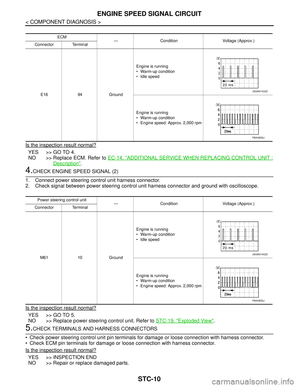
Is the inspection result normal?
YES >> GO TO 4.
NO >> Replace ECM. Refer to EC-14, "
ADDITIONAL SERVICE WHEN REPLACING CONTROL UNIT :
Description".
4.CHECK ENGINE SPEED SIGNAL (2)
1. Connect power steering control unit harness connector.
2. Check signal between power steering control unit harness connector and ground with oscilloscope.
Is the inspection result normal?
YES >> GO TO 5.
NO >> Replace power steering control unit. Refer to STC-19, "
Exploded View".
5.CHECK TERMINALS AND HARNESS CONNECTORS
Check power steering control unit pin terminals for damage or loose connection with harness connector.
Check ECM pin terminals for damage or loose connection with harness connector.
Is the inspection result normal?
YES >> INSPECTION END
NO >> Repair or replace damaged parts.
ECM
— Condition Voltage (Approx.)
Connector Terminal
E16 94 GroundEngine is running
Warm-up condition
Idle speed
Engine is running
Warm-up condition
Engine speed: Approx. 2,000 rpm
JSGIA0143ZZ
PBIA3655J
Power steering control unit
— Condition Voltage (Approx.)
Connector Terminal
M61 10 GroundEngine is running
Warm-up condition
Idle speed
Engine is running
Warm-up condition
Engine speed: Approx. 2,000 rpm
JSGIA0143ZZ
PBIA3655J
Page 4441 of 5121
POWER STEERING CONTROL UNIT
STC-13
< ECU DIAGNOSIS >
C
D
E
F
H
I
J
K
L
MA
B
STC
N
O
P
ECU DIAGNOSIS
POWER STEERING CONTROL UNIT
Reference ValueINFOID:0000000003893535
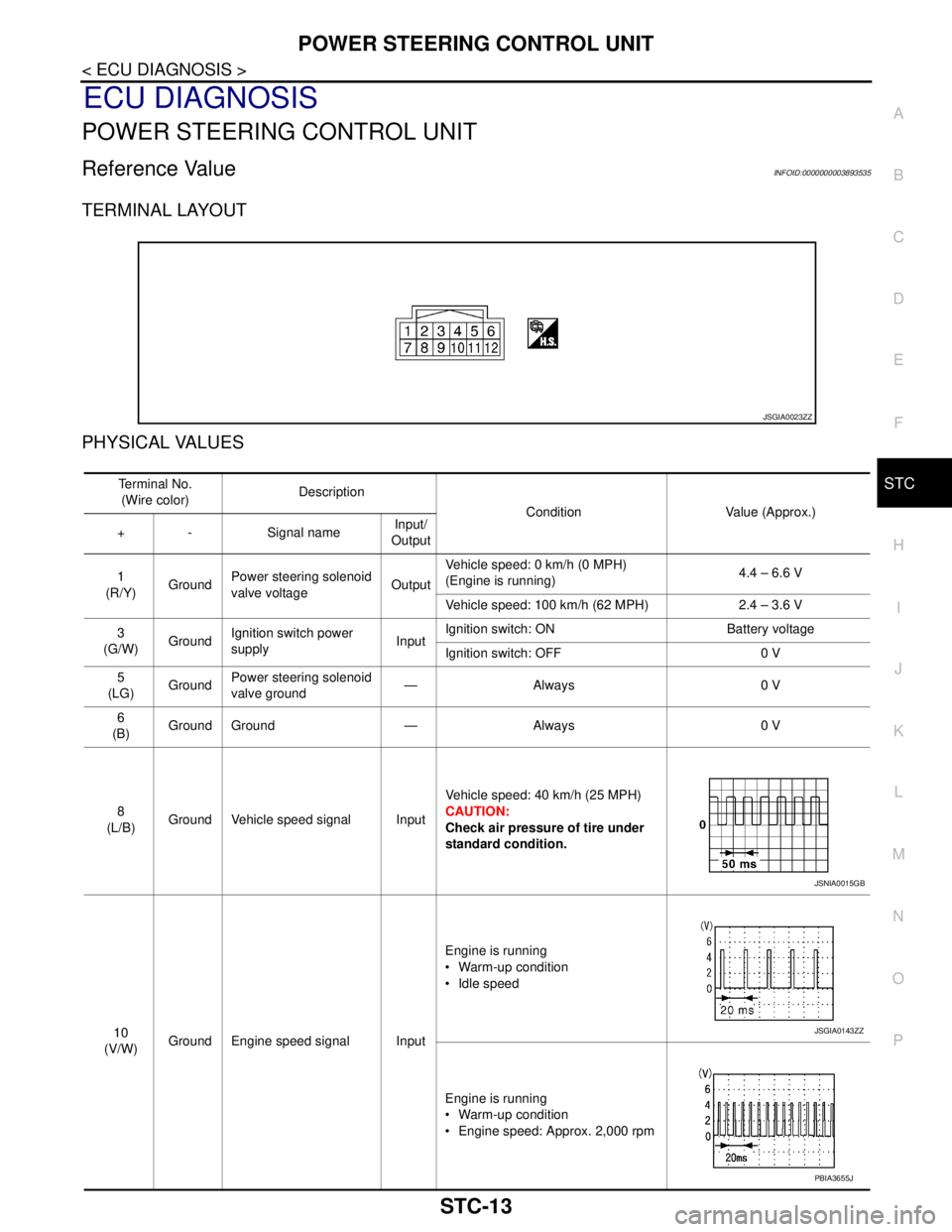
TERMINAL LAYOUT
PHYSICAL VALUES
JSGIA0023ZZ
Te r m i n a l N o .
(Wire color)Description
Condition Value (Approx.)
+ - Signal nameInput/
Output
1
(R/Y)GroundPower steering solenoid
valve voltageOutputVehicle speed: 0 km/h (0 MPH)
(Engine is running)4.4 – 6.6 V
Vehicle speed: 100 km/h (62 MPH) 2.4 – 3.6 V
3
(G/W)GroundIgnition switch power
supplyInputIgnition switch: ON Battery voltage
Ignition switch: OFF 0 V
5
(LG)GroundPower steering solenoid
valve ground—Always 0 V
6
(B)Ground Ground — Always 0 V
8
(L/B)Ground Vehicle speed signal InputVehicle speed: 40 km/h (25 MPH)
CAUTION:
Check air pressure of tire under
standard condition.
10
(V/W)Ground Engine speed signal InputEngine is running
Warm-up condition
Idle speed
Engine is running
Warm-up condition
Engine speed: Approx. 2,000 rpm
JSNIA0015GB
JSGIA0143ZZ
PBIA3655J
Page 4444 of 5121
STC-16
< ECU DIAGNOSIS >
POWER STEERING CONTROL UNIT
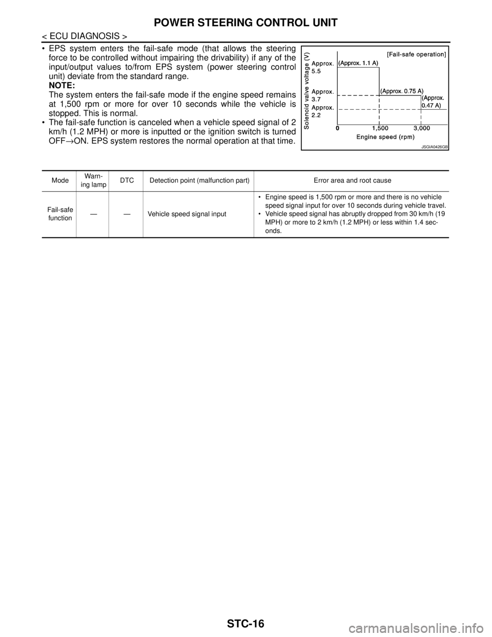
EPS system enters the fail-safe mode (that allows the steering
force to be controlled without impairing the drivability) if any of the
input/output values to/from EPS system (power steering control
unit) deviate from the standard range.
NOTE:
The system enters the fail-safe mode if the engine speed remains
at 1,500 rpm or more for over 10 seconds while the vehicle is
stopped. This is normal.
The fail-safe function is canceled when a vehicle speed signal of 2
km/h (1.2 MPH) or more is inputted or the ignition switch is turned
OFF→ON. EPS system restores the normal operation at that time.
JSGIA0426GB
ModeWarn-
ing lampDTC Detection point (malfunction part) Error area and root cause
Fail-safe
function— — Vehicle speed signal input Engine speed is 1,500 rpm or more and there is no vehicle
speed signal input for over 10 seconds during vehicle travel.
Vehicle speed signal has abruptly dropped from 30 km/h (19
MPH) or more to 2 km/h (1.2 MPH) or less within 1.4 sec-
onds.
Page 4445 of 5121
UNBALANCE STEERING WHEEL TURNING FORCE (TORQUE VARIATION)
STC-17
< SYMPTOM DIAGNOSIS >
C
D
E
F
H
I
J
K
L
MA
B
STC
N
O
P
SYMPTOM DIAGNOSIS
UNBALANCE STEERING WHEEL TURNING FORCE (TORQUE VARIA-
TION)
DescriptionINFOID:0000000003893538
Hard steering when fully turning the steering wheel.
Light steering when driving at a high speed.
Diagnosis ProcedureINFOID:0000000003893539
1.CHECK SYSTEM FOR POWER SUPPLY AND GROUND
Perform trouble diagnosis for power supply and ground. Refer to STC-6, "
Diagnosis Procedure".
Is the inspection result normal?
YES >> GO TO 2.
NO >> Repair or replace damaged parts.
2.CHECK SYSTEM FOR VEHICLE SPEED SIGNAL
Perform trouble diagnosis for vehicle speed signal. Refer to STC-11, "
Diagnosis Procedure".
Is the inspection result normal?
YES >> GO TO 3.
NO >> Repair or replace damaged parts.
3.CHECK SYSTEM FOR ENGINE SPEED SIGNAL
Perform trouble diagnosis for engine speed signal. Refer to STC-9, "
Diagnosis Procedure".
Is the inspection result normal?
YES >> GO TO 4.
NO >> Repair or replace damaged parts.
4.CHECK SYSTEM FOR POWER STEERING SOLENOID VALVE
Perform trouble diagnosis for power steering solenoid valve. Refer to STC-7, "
Diagnosis Procedure".
Is the inspection result normal?
YES >> Perform the symptom diagnosis for the steering system. Refer to ST-2, "NVH Troubleshooting
Chart".
NO >> Repair or replace damaged parts.
Page 4448 of 5121

STR-1
ENGINE
C
DE
F
G H
I
J
K L
M
SECTION STR
A
STR
N
O P
CONTENTS
STARTING SYSTEM
BASIC INSPECTION ....... .............................2
DIAGNOSIS AND REPAIR WORKFLOW ..... .....2
Work Flow ........................................................... ......2
FUNCTION DIAGNOSIS ...............................5
STARTING SYSTEM ...................................... .....5
VQ25DE ................................................................. ......5
VQ25DE : System Diagram ......................................5
VQ25DE : System Description ..................................5
VQ25DE : Component Parts Location ......................5
VQ25DE : Component Description ...........................6
VQ35DE ................................................................. ......6
VQ35DE : System Diagram ......................................6
VQ35DE : System Description ..................................6
VQ35DE : Component Parts Location ......................7
VQ35DE : Component Description ...........................7
COMPONENT DIAGNOSIS ..........................8
B TERMINAL CIRCUIT .................................. .....8
Description .......................................................... ......8
Diagnosis Procedure .................................................8
S TERMINAL CIRCUIT .......................................9
Description .......................................................... ......9
Diagnosis Procedure .................................................9
STARTING SYSTEM ..........................................10
Wiring Diagram - STARTING SYSTEM - ............ ....10
SYMPTOM DIAGNOSIS ..............................13
STARTING SYSTEM .........................................13
Symptom Table ................................................... ....13
PRECAUTION ..............................................14
PRECAUTIONS .................................................14
Precaution for Supplemental Restraint System
(SRS) "AIR BAG" and "SEAT BELT PRE-TEN-
SIONER" ............................................................. ....
14
ON-VEHICLE REPAIR .................................15
STARTER MOTOR ...........................................15
VQ25DE ................................................................. ....15
VQ25DE : Exploded View ........................................15
VQ25DE : Removal and Installation ........................16
VQ25DE : Inspection ...............................................16
VQ35DE ................................................................. ....20
VQ35DE : Exploded View ........................................20
VQ35DE : Removal and Installation ........................21
VQ35DE : Inspection ...............................................22
SERVICE DATA AND SPECIFICATIONS
(SDS) ............... .............................................
26
SERVICE DATA AND SPECIFICATIONS
(SDS) .................................................................
26
Starter Motor ....................................................... ....26
Page 4450 of 5121
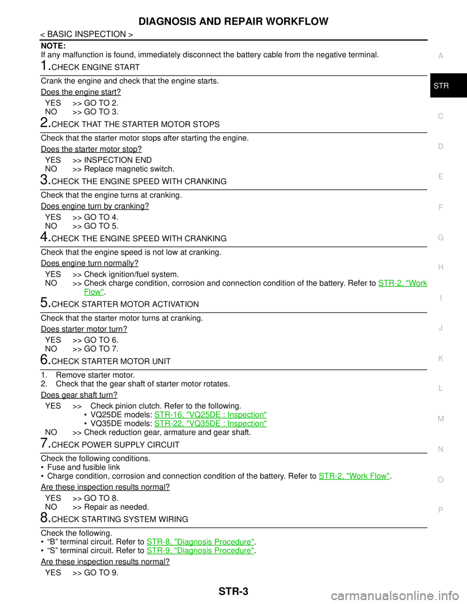
DIAGNOSIS AND REPAIR WORKFLOW
STR-3
< BASIC INSPECTION >
C
D
E
F
G
H
I
J
K
L
MA
STR
N
P O
NOTE:
If any malfunction is found, immediately disconnect the battery cable from the negative terminal.
1.CHECK ENGINE START
Crank the engine and check that the engine starts.
Does the engine start?
YES >> GO TO 2.
NO >> GO TO 3.
2.CHECK THAT THE STARTER MOTOR STOPS
Check that the starter motor stops after starting the engine.
Does the starter motor stop?
YES >> INSPECTION END
NO >> Replace magnetic switch.
3.CHECK THE ENGINE SPEED WITH CRANKING
Check that the engine turns at cranking.
Does engine turn by cranking?
YES >> GO TO 4.
NO >> GO TO 5.
4.CHECK THE ENGINE SPEED WITH CRANKING
Check that the engine speed is not low at cranking.
Does engine turn normally?
YES >> Check ignition/fuel system.
NO >> Check charge condition, corrosion and connection condition of the battery. Refer to STR-2, "
Work
Flow".
5.CHECK STARTER MOTOR ACTIVATION
Check that the starter motor turns at cranking.
Does starter motor turn?
YES >> GO TO 6.
NO >> GO TO 7.
6.CHECK STARTER MOTOR UNIT
1. Remove starter motor.
2. Check that the gear shaft of starter motor rotates.
Does gear shaft turn?
YES >> Check pinion clutch. Refer to the following.
• VQ25DE models: STR-16, "
VQ25DE : Inspection"
VQ35DE models: STR-22, "VQ35DE : Inspection"
NO >> Check reduction gear, armature and gear shaft.
7.CHECK POWER SUPPLY CIRCUIT
Check the following conditions.
Fuse and fusible link
Charge condition, corrosion and connection condition of the battery. Refer to STR-2, "
Work Flow".
Are these inspection results normal?
YES >> GO TO 8.
NO >> Repair as needed.
8.CHECK STARTING SYSTEM WIRING
Check the following.
“B” terminal circuit. Refer to STR-8, "
Diagnosis Procedure".
“S” terminal circuit. Refer to STR-9, "
Diagnosis Procedure".
Are these inspection results normal?
YES >> GO TO 9.
Page 4452 of 5121
STARTING SYSTEM
STR-5
< FUNCTION DIAGNOSIS >
C
D
E
F
G
H
I
J
K
L
MA
STR
N
P O
FUNCTION DIAGNOSIS
STARTING SYSTEM
VQ25DE
VQ25DE : System DiagramINFOID:0000000003860417
VQ25DE : System DescriptionINFOID:0000000003860418
The starter motor plunger closes and provides a closed circuit between the battery and starter motor. The
starter motor is grounded to the engine block. With power and ground supplied, cranking occurs and the
engine starts.
VQ25DE : Component Parts LocationINFOID:0000000003860419
JPBIA1991GB
JPBIA2353ZZ
Page 4453 of 5121
STR-6
< FUNCTION DIAGNOSIS >
STARTING SYSTEM
VQ25DE : Component Description
INFOID:0000000003860420
VQ35DE
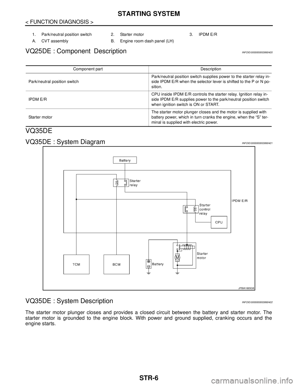
VQ35DE : System DiagramINFOID:0000000003860421
VQ35DE : System DescriptionINFOID:0000000003860422
The starter motor plunger closes and provides a closed circuit between the battery and starter motor. The
starter motor is grounded to the engine block. With power and ground supplied, cranking occurs and the
engine starts.
1. Park/neutral position switch 2. Starter motor 3. IPDM E/R
A. CVT assembly B. Engine room dash panel (LH)
Component part Description
Park/neutral position switchPark/neutral position switch supplies power to the starter relay in-
side IPDM E/R when the selector lever is shifted to the P or N po-
sition.
IPDM E/RCPU inside IPDM E/R controls the starter relay. Ignition relay in-
side IPDM E/R supplies power to the park/neutral position switch
when ignition switch is ON or START.
Starter motorThe starter motor plunger closes and the motor is supplied with
battery power, which in turn cranks the engine, when the “S” ter-
minal is supplied with electric power.
JPBIA1665GB