2008 NISSAN TEANA engine
[x] Cancel search: enginePage 4454 of 5121
STARTING SYSTEM
STR-7
< FUNCTION DIAGNOSIS >
C
D
E
F
G
H
I
J
K
L
MA
STR
N
P O
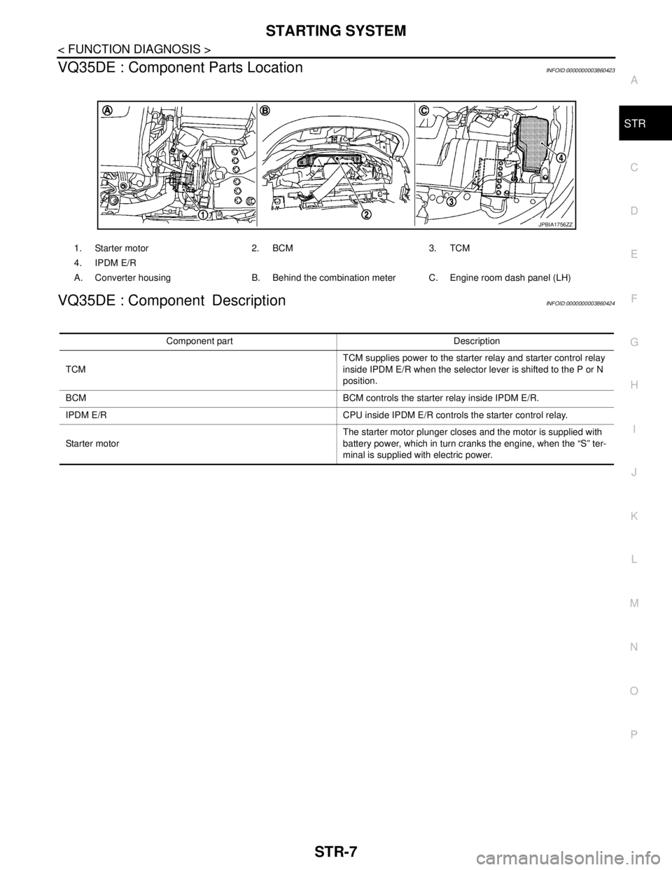
VQ35DE : Component Parts LocationINFOID:0000000003860423
VQ35DE : Component DescriptionINFOID:0000000003860424
1. Starter motor 2. BCM 3. TCM
4. IPDM E/R
A. Converter housing B. Behind the combination meter C. Engine room dash panel (LH)
JPBIA1756ZZ
Component part Description
TCMTCM supplies power to the starter relay and starter control relay
inside IPDM E/R when the selector lever is shifted to the P or N
position.
BCM BCM controls the starter relay inside IPDM E/R.
IPDM E/R CPU inside IPDM E/R controls the starter control relay.
Starter motorThe starter motor plunger closes and the motor is supplied with
battery power, which in turn cranks the engine, when the “S” ter-
minal is supplied with electric power.
Page 4455 of 5121
STR-8
< COMPONENT DIAGNOSIS >
B TERMINAL CIRCUIT
COMPONENT DIAGNOSIS
B TERMINAL CIRCUIT
DescriptionINFOID:0000000003860425
The “B” terminal is constantly supplied with battery power.
Diagnosis ProcedureINFOID:0000000003860426
CAUTION:
Perform diagnosis under the condition that engine cannot start by the following procedure.
1. Remove fuel pump fuse.
2. Crank or start the engine (where possible) until the fuel pressure is released.
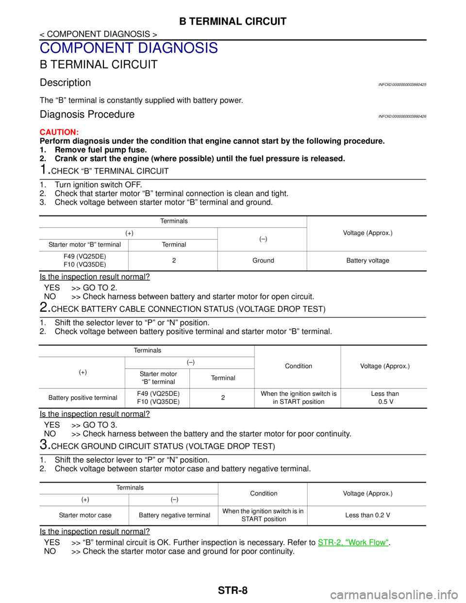
1.CHECK “B” TERMINAL CIRCUIT
1. Turn ignition switch OFF.
2. Check that starter motor “B” terminal connection is clean and tight.
3. Check voltage between starter motor “B” terminal and ground.
Is the inspection result normal?
YES >> GO TO 2.
NO >> Check harness between battery and starter motor for open circuit.
2.CHECK BATTERY CABLE CONNECTION STATUS (VOLTAGE DROP TEST)
1. Shift the selector lever to “P” or “N” position.
2. Check voltage between battery positive terminal and starter motor “B” terminal.
Is the inspection result normal?
YES >> GO TO 3.
NO >> Check harness between the battery and the starter motor for poor continuity.
3.CHECK GROUND CIRCUIT STATUS (VOLTAGE DROP TEST)
1. Shift the selector lever to “P” or “N” position.
2. Check voltage between starter motor case and battery negative terminal.
Is the inspection result normal?
YES >> “B” terminal circuit is OK. Further inspection is necessary. Refer to STR-2, "Work Flow".
NO >> Check the starter motor case and ground for poor continuity.
Te r m i n a l s
Voltage (Approx.) (+)
(–)
Starter motor “B” terminal Terminal
F49 (VQ25DE)
F10 (VQ35DE)2 Ground Battery voltage
Te r m i n a l s
Condition Voltage (Approx.)
(+)(–)
Starter motor
“B” terminalTerminal
Battery positive terminalF49 (VQ25DE)
F10 (VQ35DE)2 When the ignition switch is
in START positionLess than
0.5 V
Te r m i n a l s
Condition Voltage (Approx.)
(+) (–)
Starter motor case Battery negative terminalWhen the ignition switch is in
START positionLess than 0.2 V
Page 4456 of 5121
S TERMINAL CIRCUIT
STR-9
< COMPONENT DIAGNOSIS >
C
D
E
F
G
H
I
J
K
L
MA
STR
N
P O
S TERMINAL CIRCUIT
DescriptionINFOID:0000000003860427
The starter motor magnetic switch is supplied with power when the ignition switch is turned to START with the
selector lever “P” or “N”.
Diagnosis ProcedureINFOID:0000000003860428
CAUTION:
Perform diagnosis under the condition that engine cannot start by the following procedure.
1. Remove fuel pump fuse.
2. Crank or start the engine (where possible) until the fuel pressure is released.
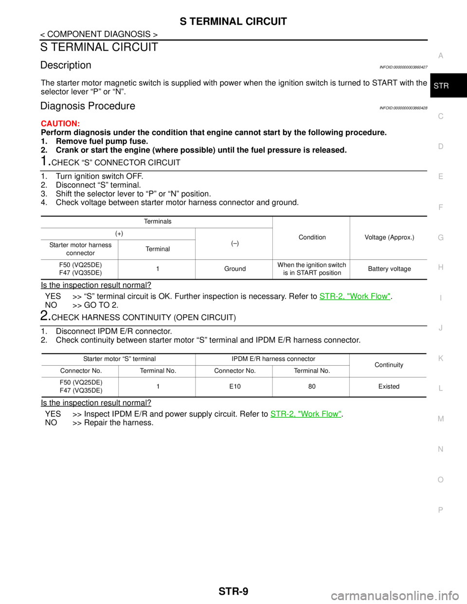
1.CHECK “S” CONNECTOR CIRCUIT
1. Turn ignition switch OFF.
2. Disconnect “S” terminal.
3. Shift the selector lever to “P” or “N” position.
4. Check voltage between starter motor harness connector and ground.
Is the inspection result normal?
YES >> “S” terminal circuit is OK. Further inspection is necessary. Refer to STR-2, "Work Flow".
NO >> GO TO 2.
2.CHECK HARNESS CONTINUITY (OPEN CIRCUIT)
1. Disconnect IPDM E/R connector.
2. Check continuity between starter motor “S” terminal and IPDM E/R harness connector.
Is the inspection result normal?
YES >> Inspect IPDM E/R and power supply circuit. Refer to STR-2, "Work Flow".
NO >> Repair the harness.
Te r m i n a l s
Condition Voltage (Approx.) (+)
(–)
Starter motor harness
connectorTe r m i n a l
F50 (VQ25DE)
F47 (VQ35DE)1 GroundWhen the ignition switch
is in START positionBattery voltage
Starter motor “S” terminal IPDM E/R harness connector
Continuity
Connector No. Terminal No. Connector No. Terminal No.
F50 (VQ25DE)
F47 (VQ35DE)1E1080Existed
Page 4475 of 5121

TM-2
DTC Logic ...............................................................47
Diagnosis Procedure ..............................................47
Component Inspection ............................................48
P0710 CVT FLUID TEMPERATURE SENSOR
...
50
Description ..............................................................50
DTC Logic ...............................................................50
Diagnosis Procedure ..............................................50
Component Inspection (CVT Fluid Temperature
Sensor) ...................................................................
51
P0715 INPUT SPEED SENSOR (PRI SPEED
SENSOR) ...........................................................
52
Description ..............................................................52
DTC Logic ...............................................................52
Diagnosis Procedure ..............................................52
P0720 VEHICLE SPEED SENSOR CVT (SEC-
ONDARY SPEED SENSOR) .............................
55
Description ..............................................................55
DTC Logic ...............................................................55
Diagnosis Procedure ..............................................55
P0725 ENGINE SPEED SIGNAL ......................59
Description ..............................................................59
DTC Logic ...............................................................59
Diagnosis Procedure ..............................................59
P0730 BELT DAMAGE ......................................60
Description ..............................................................60
DTC Logic ...............................................................60
Diagnosis Procedure ..............................................60
P0740 TORQUE CONVERTER CLUTCH SO-
LENOID VALVE .................................................
62
Description ..............................................................62
DTC Logic ...............................................................62
Diagnosis Procedure ..............................................62
Component Inspection (Torque Converter Clutch
Solenoid Valve) ......................................................
63
P0744 A/T TCC S/V FUNCTION (LOCK -UP) ...64
Description ..............................................................64
DTC Logic ...............................................................64
Diagnosis Procedure ..............................................64
Component Inspection (Torque Converter Clutch
Solenoid Valve) ......................................................
65
Component Inspection (Lock-up Select Solenoid
Valve) .....................................................................
65
P0745 LINE PRESSURE SOLENOID VALVE ...66
Description ..............................................................66
DTC Logic ...............................................................66
Diagnosis Procedure ..............................................66
Component Inspection [Pressure Control Sole-
noid Valve A (Line Pressure Solenoid Valve)] ........
67
P0746 PRESSURE CONTROL SOLENOID A
PERFORMANCE (LINE PRESSURE SOLE-
NOID VALVE) ....................................................
68
Description ..............................................................68
DTC Logic ...............................................................68
Diagnosis Procedure ...............................................68
Component Inspection [Pressure Control Sole-
noid Valve A (Line Pressure Solenoid Valve)] ........
69
P0776 PRESSURE CONTROL SOLENOID B
PERFORMANCE (SEC PRESSURE SOLE-
NOID VALVE) ....................................................
70
Description ..............................................................70
DTC Logic ...............................................................70
Diagnosis Procedure ...............................................70
Component Inspection [Pressure Control Sole-
noid Valve A (Line Pressure Solenoid Valve)] ........
71
Component Inspection [Pressure Control Sole-
noid Valve B (Secondary Pressure Solenoid
Valve)] .....................................................................
71
P0778 PRESSURE CONTROL SOLENOID B
ELECTRICAL (SEC PRESSURE SOLENOID
VALVE) ..............................................................
72
Description ..............................................................72
DTC Logic ...............................................................72
Diagnosis Procedure ...............................................72
Component Inspection [Pressure Control Sole-
noid Valve B (Secondary Pressure Solenoid
Valve)] .....................................................................
73
P0840 TRANSMISSION FLUID PRESSURE
SENSOR A (SEC PRESSURE SENSOR) .........
74
Description ..............................................................74
DTC Logic ...............................................................74
Diagnosis Procedure ...............................................74
P0841 PRESSURE SENSOR FUNCTION ........77
Description ..............................................................77
DTC Logic ...............................................................77
Diagnosis Procedure ...............................................77
Component Inspection [Pressure Control Sole-
noid Valve A (Line Pressure Solenoid Valve)] ........
78
Component Inspection [Pressure Control Sole-
noid Valve B (Secondary Pressure Solenoid
Valve)] .....................................................................
78
P0845 TRANSMISSION FLUID PRESSURE
SENSOR B (PRI PRESSURE SENSOR) ..........
80
Description ..............................................................80
DTC Logic ...............................................................80
Diagnosis Procedure ...............................................80
P0868 SECONDARY PRESSURE DOWN ........83
Description ..............................................................83
DTC Logic ...............................................................83
Diagnosis Procedure ...............................................83
Component Inspection [Pressure Control Sole-
noid Valve A (Line Pressure Solenoid Valve)] ........
84
Page 4476 of 5121
![NISSAN TEANA 2008 Service Manual TM-3
C
E
F
G
H
I
J
K
L
MA
B
TM
N
O
P Component Inspection [Pressure Control Sole-
noid Valve B (Secondary Pressure Solenoid
Valve)] ................................................................... NISSAN TEANA 2008 Service Manual TM-3
C
E
F
G
H
I
J
K
L
MA
B
TM
N
O
P Component Inspection [Pressure Control Sole-
noid Valve B (Secondary Pressure Solenoid
Valve)] ...................................................................](/manual-img/5/57391/w960_57391-4475.png)
TM-3
C
E
F
G
H
I
J
K
L
MA
B
TM
N
O
P Component Inspection [Pressure Control Sole-
noid Valve B (Secondary Pressure Solenoid
Valve)] .....................................................................
84
P1701 TRANSMISSION CONTROL MODULE
(POWER SUPPLY) .............................................
85
Description ..............................................................85
DTC Logic ...............................................................85
Diagnosis Procedure ...............................................85
P1705 THROTTLE POSITION SENSOR ...........88
Description ..............................................................88
DTC Logic ...............................................................88
Diagnosis Procedure ...............................................88
P1722 ESTM VEHICLE SPEED SIGNAL ..........89
Description ..............................................................89
DTC Logic ...............................................................89
Diagnosis Procedure ...............................................89
P1723 CVT SPEED SENSOR FUNCTION ........91
Description ..............................................................91
DTC Logic ...............................................................91
Diagnosis Procedure ...............................................91
P1726 ELECTRIC THROTTLE CONTROL
SYSTEM .............................................................
93
Description ..............................................................93
DTC Logic ...............................................................93
Diagnosis Procedure ...............................................93
P1740 LOCK-UP SELECT SOLENOID
VALVE ................................................................
94
Description ..............................................................94
DTC Logic ...............................................................94
Diagnosis Procedure ...............................................94
Component Inspection (Lock-up Select Solenoid
Valve) ......................................................................
95
P1745 LINE PRESSURE CONTROL .................96
Description ..............................................................96
DTC Logic ...............................................................96
Diagnosis Procedure ...............................................96
P1777 STEP MOTOR .........................................97
Description ..............................................................97
DTC Logic ...............................................................97
Diagnosis Procedure ...............................................97
Component Inspection (Step Motor) .......................98
P1778 STEP MOTOR - FUNCTION .................100
Description ............................................................100
DTC Logic .............................................................100
Diagnosis Procedure .............................................100
SHIFT POSITION INDICATOR CIRCUIT .........102
Description ............................................................102
Component Function Check ..................................102
Diagnosis Procedure .............................................102
SHIFT LOCK SYSTEM .....................................103
Description .............................................................103
Wiring Diagram - CVT SHIFT LOCK SYSTEM - ...103
Component Function Check ..................................105
Diagnosis Procedure .............................................106
Component Inspection (Stop Lamp Switch) ..........107
SPORT MODE SWITCH .................................108
Description .............................................................108
Component Function Check ..................................108
Diagnosis Procedure .............................................108
ECU DIAGNOSIS .......................................111
TCM .................................................................111
Reference Value ....................................................111
Wiring Diagram - CVT CONTROL SYSTEM - .......116
Fail-safe .................................................................120
DTC Inspection Priority Chart ................................121
DTC Index .............................................................121
SYMPTOM DIAGNOSIS ............................123
SYSTEM SYMPTOM .......................................123
Symptom Table .....................................................123
PRECAUTION ............................................135
PRECAUTIONS ...............................................135
Precaution for Supplemental Restraint System
(SRS) "AIR BAG" and "SEAT BELT PRE-TEN-
SIONER" ...............................................................
135
Precaution Necessary for Steering Wheel Rota-
tion after Battery Disconnect .................................
135
Precaution for Procedure without Cowl Top Cover ..136
Precaution for On Board Diagnosis (OBD) System
of CVT and Engine ................................................
136
Precaution for TCM and CVT Assembly Replace-
ment .......................................................................
136
Removal and Installation Procedure for CVT Unit
Connector ..............................................................
136
Precaution .............................................................138
Service Notice or Precaution .................................138
ATFTEMP COUNT Conversion Table ...................139
PREPARATION .........................................140
PREPARATION ...............................................140
Special Service Tools ............................................140
Commercial Service Tools .....................................140
ON-VEHICLE MAINTENANCE ..................142
CVT FLUID ......................................................142
Inspection ..............................................................142
Changing ...............................................................143
STALL TEST ...................................................144
Inspection and Judgment ......................................144
LINE PRESSURE TEST ..................................146
Inspection and Judgment ......................................146
Page 4477 of 5121

TM-4
ROAD TEST .....................................................148
Description .............................................................148
Check before Engine Is Started .............................148
Check at Idle ..........................................................149
Cruise Test ............................................................150
CVT POSITION ................................................152
Inspection and Adjustment ....................................152
ON-VEHICLE REPAIR ...............................153
TRANSMISSION CONTROL MODULE ..........153
Exploded View .......................................................153
Removal and Installation .......................................153
Adjustment .............................................................154
CONTROL DEVICE .........................................155
Exploded View .......................................................155
Removal and Installation .......................................155
Inspection and Adjustment ....................................156
CONTROL CABLE ..........................................157
Exploded View .......................................................157
Removal and Installation .......................................157
Inspection and Adjustment ....................................158
OIL PAN ...........................................................159
Exploded View .......................................................159
Removal and Installation .......................................159
Inspection ..............................................................160
SECONDARY SPEED SENSOR .....................161
Exploded View .......................................................161
Removal and Installation .......................................161
Inspection ..............................................................161
DIFFERENTIAL SIDE OIL SEAL ....................162
Exploded View .......................................................162
Removal and Installation .......................................162
Inspection ..............................................................163
AIR BREATHER HOSE ...................................164
Exploded View .......................................................164
Removal and Installation .......................................164
FLUID COOLER SYSTEM ...............................165
Exploded View .......................................................165
Removal and Installation .......................................165
Inspection ..............................................................167
REMOVAL AND INSTALLATION ..............168
TRANSAXLE ASSEMBLY ..............................168
Exploded View .......................................................168
Removal and Installation .......................................168
Inspection ..............................................................170
DISASSEMBLY AND ASSEMBLY ............172
TORQUE CONVERTER ..................................172
Exploded View .......................................................172
Disassembly ..........................................................172
Assembly ..............................................................172
Inspection ..............................................................173
SERVICE DATA AND SPECIFICATIONS
(SDS) .........................................................
174
SERVICE DATA AND SPECIFICATIONS
(SDS) ................................................................
174
General Specification ............................................174
Vehicle Speed When Shifting Gears .....................174
Stall Speed ............................................................174
Line Pressure ........................................................174
Solenoid Valves ....................................................175
CVT Fluid Temperature Sensor ............................175
Primary Speed Sensor ..........................................175
Secondary Speed Sensor .....................................175
Step Motor ............................................................175
Torque Converter ..................................................175
CVT: RE0F10A
BASIC INSPECTION .................................
176
DIAGNOSIS AND REPAIR WORK FLOW .......176
Work Flow .............................................................176
Diagnostic Work Sheet .........................................177
INSPECTION AND ADJUSTMENT ..................179
ADDITIONAL SERVICE WHEN REPLACING
CONTROL UNIT ......................................................
179
ADDITIONAL SERVICE WHEN REPLACING
CONTROL UNIT : Service After Replacing TCM
and Transaxle Assembly .......................................
179
FUNCTION DIAGNOSIS ...........................181
CVT SYSTEM ...................................................181
System Diagram ...................................................181
Component Parts Location ...................................182
MECHANICAL SYSTEM ..................................183
Cross-Sectional View ............................................183
System Diagram ...................................................184
System Description ...............................................184
Component Parts Location ...................................185
Component Description ........................................186
HYDRAULIC CONTROL SYSTEM ..................187
System Diagram ...................................................187
System Description ...............................................187
Component Parts Location ...................................188
Component Description ........................................189
CONTROL SYSTEM .........................................190
System Diagram ...................................................190
System Description ...............................................190
Component Parts Location ...................................192
Component Description ........................................193
LOCK-UP AND SELECT CONTROL SYSTEM
..
194
Page 4478 of 5121
TM-5
C
E
F
G
H
I
J
K
L
MA
B
TM
N
O
P System Diagram ....................................................
194
System Description ...............................................194
Component Parts Location ....................................195
Component Description .........................................196
SHIFT CONTROL SYSTEM .............................197
System Diagram ....................................................197
System Description ...............................................197
Component Parts Location ....................................198
Component Description .........................................199
SHIFT LOCK SYSTEM .....................................200
System Description ...............................................200
Component Parts Location ....................................201
Component Description .........................................201
ON BOARD DIAGNOSTIC (OBD) SYSTEM ....202
Diagnosis Description ...........................................202
DIAGNOSIS SYSTEM (TCM) ...........................204
CONSULT-III Function (TRANSMISSION) ...........204
Diagnostic Tool Function .......................................207
COMPONENT DIAGNOSIS .......................208
U1000 CAN COMM CIRCUIT ...........................208
Description ............................................................208
DTC Logic .............................................................208
Diagnosis Procedure .............................................208
U1010 CONTROL UNIT (CAN) ........................209
Description ............................................................209
DTC Logic .............................................................209
Diagnosis Procedure .............................................209
P0703 STOP LAMP SWITCH ..........................210
Description ............................................................210
DTC Logic .............................................................210
Diagnosis Procedure .............................................210
Component Inspection (Stop Lamp Switch) ..........211
P0705 PARK/NEUTRAL POSITION SWITCH ..213
Description ............................................................213
DTC Logic .............................................................213
Diagnosis Procedure .............................................213
Component Inspection (Park/Neutral Position
Switch) ..................................................................
214
P0710 CVT FLUID TEMPERATURE SENSOR
..
216
Description ............................................................216
DTC Logic .............................................................216
Diagnosis Procedure .............................................216
Component Inspection (CVT Fluid Temperature
Sensor) ..................................................................
217
P0715 INPUT SPEED SENSOR (PRI SPEED
SENSOR) ..........................................................
218
Description ............................................................218
DTC Logic .............................................................218
Diagnosis Procedure .............................................218
P0720 VEHICLE SPEED SENSOR CVT (SEC-
ONDARY SPEED SENSOR) ...........................
222
Description .............................................................222
DTC Logic ..............................................................222
Diagnosis Procedure .............................................222
P0725 ENGINE SPEED SIGNAL ....................226
Description .............................................................226
DTC Logic ..............................................................226
Diagnosis Procedure .............................................226
P0730 BELT DAMAGE ...................................228
Description .............................................................228
DTC Logic ..............................................................228
Diagnosis Procedure .............................................228
P0740 TORQUE CONVERTER CLUTCH SO-
LENOID VALVE ..............................................
230
Description .............................................................230
DTC Logic ..............................................................230
Diagnosis Procedure .............................................230
Component Inspection (Torque Converter Clutch
Solenoid Valve) .....................................................
231
P0744 A/T TCC S/V FUNCTION (LOCK -UP) .232
Description .............................................................232
DTC Logic ..............................................................232
Diagnosis Procedure .............................................232
Component Inspection (Torque Converter Clutch
Solenoid Valve) .....................................................
233
Component Inspection (Lock-up Select Solenoid
Valve) ....................................................................
233
P0745 LINE PRESSURE SOLENOID VALVE .234
Description .............................................................234
DTC Logic ..............................................................234
Diagnosis Procedure .............................................234
Component Inspection [Pressure Control Sole-
noid Valve A (Line Pressure Solenoid Valve)] .......
235
P0746 PRESSURE CONTROL SOLENOID A
PERFORMANCE (LINE PRESSURE SOLE-
NOID VALVE) ..................................................
236
Description .............................................................236
DTC Logic ..............................................................236
Diagnosis Procedure .............................................236
Component Inspection [Pressure Control Sole-
noid Valve A (Line Pressure Solenoid Valve)] .......
237
P0776 PRESSURE CONTROL SOLENOID B
PERFORMANCE (SEC PRESSURE SOLE-
NOID VALVE) ..................................................
238
Description .............................................................238
DTC Logic ..............................................................238
Diagnosis Procedure .............................................238
Component Inspection [Pressure Control Sole-
noid Valve A (Line Pressure Solenoid Valve)] .......
239
Component Inspection [Pressure Control Sole-
noid Valve B (Secondary Pressure Solenoid
Valve)] ...................................................................
239
Page 4480 of 5121
TM-7
C
E
F
G
H
I
J
K
L
MA
B
TM
N
O
P Precaution for Supplemental Restraint System
(SRS) "AIR BAG" and "SEAT BELT PRE-TEN-
SIONER" ...............................................................
297
Precaution Necessary for Steering Wheel Rota-
tion after Battery Disconnect .................................
297
Precaution for Procedure without Cowl Top Cover ..298
Precaution for On Board Diagnosis (OBD) System
of CVT and Engine ................................................
298
Precaution for TCM and CVT Assembly Replace-
ment ......................................................................
298
Removal and Installation Procedure for CVT Unit
Connector ..............................................................
298
Precaution .............................................................299
Service Notice or Precaution .................................300
ATFTEMP COUNT Conversion Table ..................301
PREPARATION .........................................302
PREPARATION ................................................302
Special Service Tools ............................................302
Commercial Service Tools ....................................302
ON-VEHICLE MAINTENANCE ..................304
CVT FLUID .......................................................304
Inspection ..............................................................304
Changing ...............................................................305
STALL TEST ....................................................306
Inspection and Judgment ......................................306
LINE PRESSURE TEST ...................................308
Inspection and Judgment ......................................308
ROAD TEST .....................................................310
Description ............................................................310
Check before Engine Is Started ............................310
Check at Idle .........................................................311
Cruise Test ............................................................312
CVT POSITION .................................................314
Inspection and Adjustment ....................................314
ON-VEHICLE REPAIR ...............................315
TRANSMISSION CONTROL MODULE ...........315
Exploded View ......................................................315
Removal and Installation .......................................315
CONTROL DEVICE ..........................................317
Exploded View ......................................................317
Removal and Installation .......................................317
Inspection and Adjustment ....................................318
CONTROL CABLE ...........................................319
Exploded View ......................................................319
Removal and Installation .......................................319
Inspection and Adjustment ....................................320
OIL PAN ...........................................................321
Exploded View ......................................................321
Removal and Installation .......................................321
Inspection ..............................................................322
PRIMARY SPEED SENSOR ...........................323
Exploded View .......................................................323
Removal and Installation .......................................323
Inspection ..............................................................323
SECONDARY SPEED SENSOR ....................324
Exploded View .......................................................324
Removal and Installation .......................................324
Inspection ..............................................................324
DIFFERENTIAL SIDE OIL SEAL ....................325
Exploded View .......................................................325
Removal and Installation .......................................325
Inspection ..............................................................326
OIL PUMP FITTING BOLT ..............................327
Description .............................................................327
Exploded View .......................................................327
Removal and Installation .......................................327
Inspection ..............................................................327
AIR BREATHER HOSE ..................................328
Exploded View .......................................................328
Removal and Installation .......................................328
FLUID COOLER SYSTEM ..............................329
Exploded View .......................................................329
Removal and Installation .......................................329
Inspection ..............................................................331
REMOVAL AND INSTALLATION .............332
TRANSAXLE ASSEMBLY ..............................332
Exploded View .......................................................332
Removal and Installation .......................................332
Inspection ..............................................................334
DISASSEMBLY AND ASSEMBLY ............335
TORQUE CONVERTER AND CONVERTER
HOUSING OIL SEAL ......................................
335
Exploded View .......................................................335
Disassembly ..........................................................335
Assembly ...............................................................335
Inspection ..............................................................336
SERVICE DATA AND SPECIFICATIONS
(SDS) ..........................................................
337
SERVICE DATA AND SPECIFICATIONS
(SDS) ...............................................................
337
General Specification ............................................337
Vehicle Speed When Shifting Gears .....................337
Stall Speed ............................................................337
Line Pressure ........................................................337
Solenoid Valves .....................................................338
CVT Fluid Temperature Sensor .............................338
Primary Speed Sensor ..........................................338
Secondary Speed Sensor ......................................338