2008 NISSAN LATIO window
[x] Cancel search: windowPage 536 of 2771

BL-102
< SERVICE INFORMATION >
INTELLIGENT KEY SYSTEM
* : Sedan
WORK SUPPORT
Te s t i t e m D e s c r i p t i o n
DOOR LOCK/UNLOCKThis test is able to check door lock/unlock operation.
• The all door lock actuators are unlocked when “ALL UNLK” on CONSULT-III screen is touched.
• The all door lock actuators are locked when “LOCK” on CONSULT-III screen is touched.
ANTENNAThis test is able to check Intelligent Key antenna operation.
When the following conditions are met, hazard warning lamps flash.
• Inside key antenna (front console) detects Intelligent Key, when “ROOM ANT1” on CONSULT-
III screen is touched.
• Inside key antenna (instrument panel and rear floor) detects Intelligent Key, when “ROOM
ANT2” on CONSULT-III screen is touched.
• Outside key antenna (driver side) detects Intelligent Key, when “DRIVER ANT” on CONSULT-III
screen is touched.
• Outside key antenna (passenger side) detects Intelligent Key, when “ASSIST ANT” on CON-
SULT-III screen is touched.
• Outside key antenna (rear bumper) detects Intelligent Key, when “BK DOOR ANT” on CON-
SULT-III screen is touched.
OUTSIDE BUZZER(S)
(DRIVER DOOR), (TRUNK)
*This test is able to check Intelligent Key warning buzzer operation.
Intelligent Key warning buzzer sounds when “ON” on CONSULT-III screen is touched.
INSIDE BUZZER
(CHIME)This test is able to check Intelligent Key warning chime (Instrument panel) operation.
• Take away warning chime sounds when “TAKE OUT” on CONSULT-III screen is touched.
• Ignition switch warning chime sounds when “KNOB” on CONSULT-III screen is touched.
• Ignition key warning chime sounds when “KEY” on CONSULT-III screen is touched.
INDICATORThis test is able to check warning lamp operation.
• “KEY” Warning lamp (Green) illuminates when “BLUE ON” on CONSULT-III screen is touched.
• “KEY” Warning lamp (Red) illuminates when “RED ON” on CONSULT-III screen is touched.
• “LOCK” Warning lamp illuminates when “KNOB ON” on CONSULT-III screen is touched.
• “KEY” Warning lamp (Green) flashes when “BLUE IND” on CONSULT-III screen is touched.
• “KEY” Warning lamp (RED) flashes when “BLUE IND” on CONSULT-III screen is touched.
• “P-SHIFT” Warning lamp flashes when “KNOB ON” on CONSULT-III screen is touched.
Monitor item Description
CONFIRM KEY FOB ID It can be checked whether Intelligent Key ID code is registered or not in this mode.
TAKE OUT FROM WINDOW
WARNTake away warning chime (from window) mode can be changed to operate (ON) or not operate
(OFF) with this mode. The operation mode will be changed when “CHANGE SETT” on CONSULT-
III screen is touched.
LOW BAT OF KEY FOB WARNIntelligent Key low battery warning mode can be changed to operate (ON) or not operate (OFF)
with this mode. The operation mode will be changed when “CHANGE SETT” on CONSULT-III
screen is touched.
ANSWER BACK FUNCTIONBuzzer reminder function mode by Intelligent button can be changed to operate (ON) or not oper-
ate (OFF) with this mode. The operation mode will be changed when “CHANGE SETT” on CON-
SULT-III screen is touched.
SELECTIVE UNLOCK FUNC-
TIONSelective unlock function mode can be changed to operate (ON) or not operate (OFF) with this
mode. The operation mode will be changed when “CHANGE SETT” on CONSULT-III screen is
touched.
ANTI KEY LOCK IN FUNCTIONKey reminder function mode can be changed to operate (ON) or not operate (OFF) with this mode.
The operation mode will be changed when “CHANGE SETT” on CONSULT-III screen is touched.
HORN WITH KEYLESS LOCKHorn reminder function mode by Intelligent Key remote control button can be changed to operate
(ON) or not operate (OFF) with this mode. The operation mode will be changed when “CHANGE
SETT” on CONSULT-III screen is touched.
HAZARD ANSWER BACKHazard reminder function mode can be selected from the following with this mode. The operation
mode will be changed when “CHANGE SETT” on CONSULT-III screen is touched.
• LOCK ONLY: Door lock operation only
• UNLOCK ONLY: Door unlock operation only
• LOCK/UNLOCK: Lock/Unlock operation
• OFF: Non-operation
Page 543 of 2771
INTELLIGENT KEY SYSTEM
BL-109
< SERVICE INFORMATION >
C
D
E
F
G
H
J
K
L
MA
B
BL
N
O
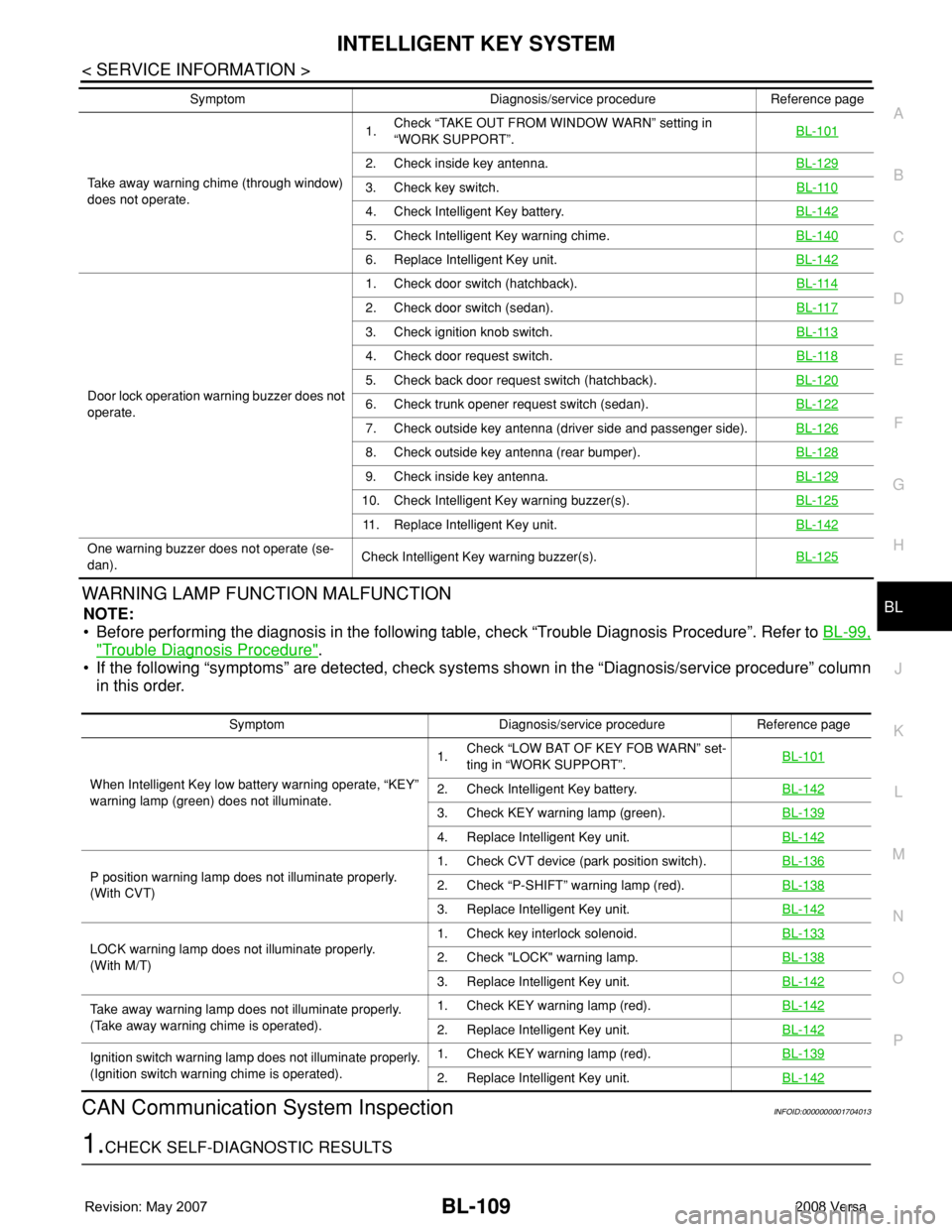
PWARNING LAMP FUNCTION MALFUNCTION
NOTE:
• Before performing the diagnosis in the following table, check “Trouble Diagnosis Procedure”. Refer to BL-99,
"Trouble Diagnosis Procedure".
• If the following “symptoms” are detected, check systems shown in the “Diagnosis/service procedure” column
in this order.
CAN Communication System InspectionINFOID:0000000001704013
1.CHECK SELF-DIAGNOSTIC RESULTS
Take away warning chime (through window)
does not operate.1.Check “TAKE OUT FROM WINDOW WARN” setting in
“WORK SUPPORT”.BL-101
2. Check inside key antenna.BL-129
3. Check key switch.BL-110
4. Check Intelligent Key battery.BL-142
5. Check Intelligent Key warning chime.BL-140
6. Replace Intelligent Key unit.BL-142
Door lock operation warning buzzer does not
operate.1. Check door switch (hatchback).BL-114
2. Check door switch (sedan).BL-117
3. Check ignition knob switch.BL-113
4. Check door request switch.BL-118
5. Check back door request switch (hatchback).BL-120
6. Check trunk opener request switch (sedan).BL-122
7. Check outside key antenna (driver side and passenger side).BL-126
8. Check outside key antenna (rear bumper).BL-128
9. Check inside key antenna.BL-129
10. Check Intelligent Key warning buzzer(s).BL-125
11. Replace Intelligent Key unit.BL-142
One warning buzzer does not operate (se-
dan).Check Intelligent Key warning buzzer(s).BL-125
Symptom Diagnosis/service procedure Reference page
Symptom Diagnosis/service procedure Reference page
When Intelligent Key low battery warning operate, “KEY”
warning lamp (green) does not illuminate.1.Check “LOW BAT OF KEY FOB WARN” set-
ting in “WORK SUPPORT”.BL-101
2. Check Intelligent Key battery.BL-142
3. Check KEY warning lamp (green).BL-139
4. Replace Intelligent Key unit.BL-142
P position warning lamp does not illuminate properly.
(With CVT)1. Check CVT device (park position switch).BL-1362. Check “P-SHIFT” warning lamp (red).BL-138
3. Replace Intelligent Key unit.BL-142
LOCK warning lamp does not illuminate properly.
(With M/T)1. Check key interlock solenoid.BL-1332. Check "LOCK" warning lamp.BL-138
3. Replace Intelligent Key unit.BL-142
Take away warning lamp does not illuminate properly.
(Take away warning chime is operated).1. Check KEY warning lamp (red).BL-142
2. Replace Intelligent Key unit.BL-142
Ignition switch warning lamp does not illuminate properly.
(Ignition switch warning chime is operated).1. Check KEY warning lamp (red).BL-139
2. Replace Intelligent Key unit.BL-142
Page 580 of 2771
BL-146
< SERVICE INFORMATION >
DOOR
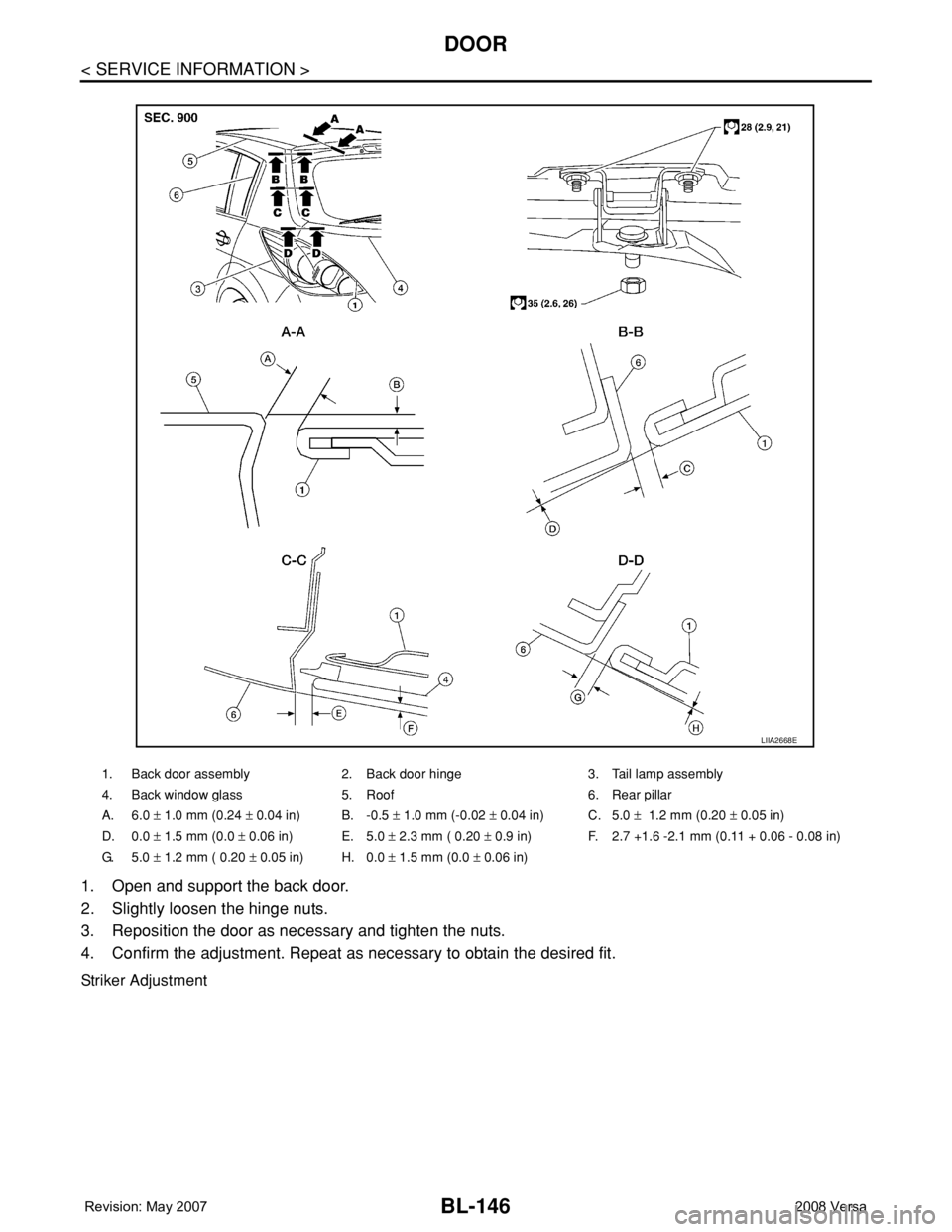
1. Open and support the back door.
2. Slightly loosen the hinge nuts.
3. Reposition the door as necessary and tighten the nuts.
4. Confirm the adjustment. Repeat as necessary to obtain the desired fit.
Striker Adjustment
1. Back door assembly 2. Back door hinge 3. Tail lamp assembly
4. Back window glass 5. Roof 6. Rear pillar
A. 6.0 ± 1.0 mm (0.24 ± 0.04 in) B. -0.5 ± 1.0 mm (-0.02 ± 0.04 in) C. 5.0 ± 1.2 mm (0.20 ± 0.05 in)
D. 0.0 ± 1.5 mm (0.0 ± 0.06 in) E. 5.0 ± 2.3 mm ( 0.20 ± 0.9 in) F. 2.7 +1.6 -2.1 mm (0.11 + 0.06 - 0.08 in)
G. 5.0 ± 1.2 mm ( 0.20 ± 0.05 in) H. 0.0 ± 1.5 mm (0.0 ± 0.06 in)
LIIA2668E
Page 584 of 2771
BL-150
< SERVICE INFORMATION >
FRONT DOOR LOCK
FRONT DOOR LOCK
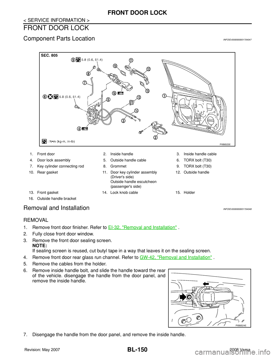
Component Parts LocationINFOID:0000000001704047
Removal and InstallationINFOID:0000000001704048
REMOVAL
1. Remove front door finisher. Refer to EI-32, "Removal and Installation" .
2. Fully close front door window.
3. Remove the front door sealing screen.
NOTE:
If sealing screen is reused, cut butyl tape in a way that leaves it on the sealing screen.
4. Remove front door rear glass run channel. Refer to GW-42, "
Removal and Installation" .
5. Remove the cables from the holder.
6. Remove inside handle bolt, and slide the handle toward the rear
of the vehicle. disengage the handle from the door panel, and
remove the inside handle.
7. Disengage the handle from the door panel, and remove the inside handle.
1. Front door 2. Inside handle 3. Inside handle cable
4. Door lock assembly 5. Outside handle cable 6. TORX bolt (T30)
7. Key cylinder connecting rod 8. Grommet 9. TORX bolt (T30)
10. Rear gasket 11. Door key cylinder assembly
(Driver's side)
Outside handle escutcheon
(passenger's side)12. Outside handle
13. Front gasket 14. Lock knob cable 15. Holder
16. Outside handle bracket
PIIB6523E
PIIB6524E
Page 587 of 2771
REAR DOOR LOCK
BL-153
< SERVICE INFORMATION >
C
D
E
F
G
H
J
K
L
MA
B
BL
N
O
P
REAR DOOR LOCK
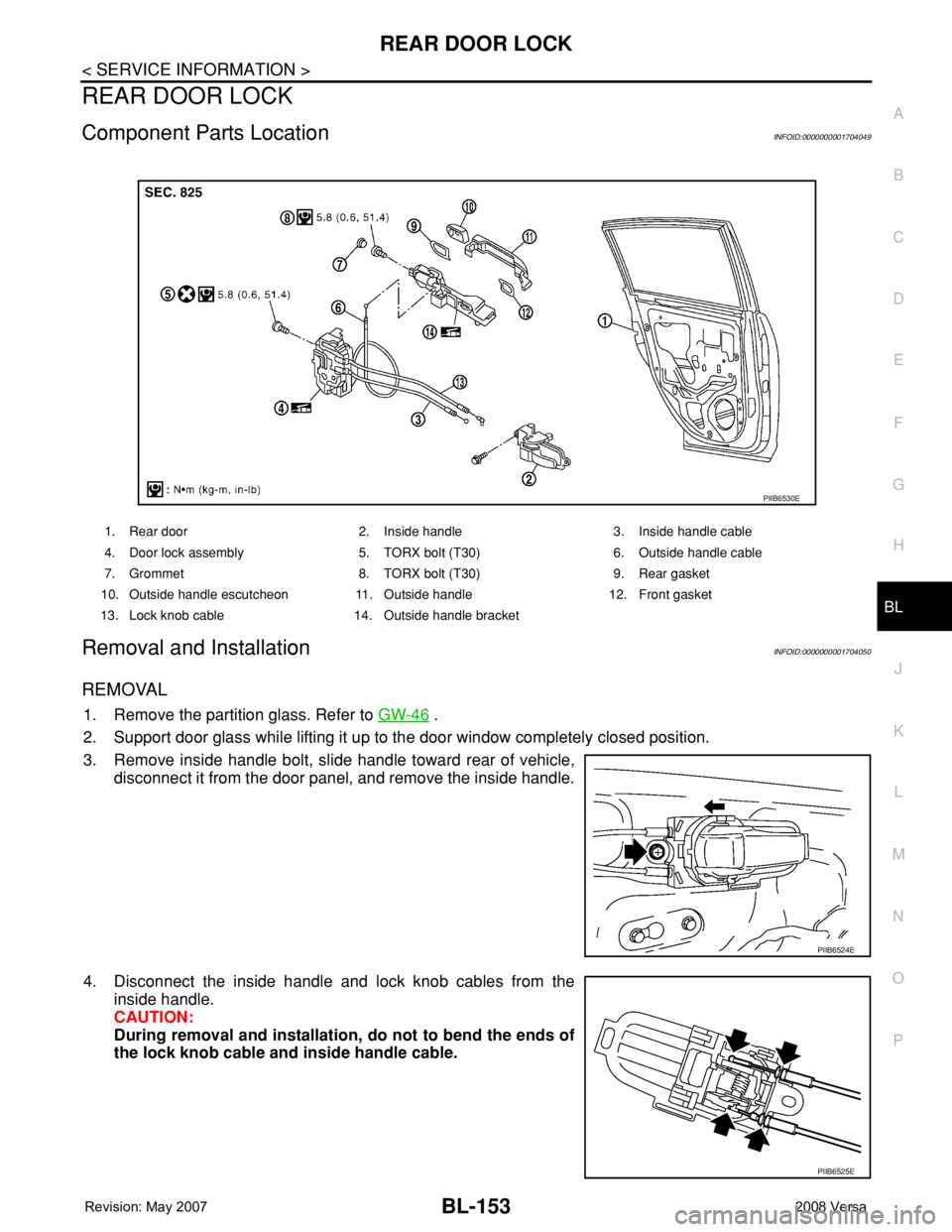
Component Parts LocationINFOID:0000000001704049
Removal and InstallationINFOID:0000000001704050
REMOVAL
1. Remove the partition glass. Refer to GW-46 .
2. Support door glass while lifting it up to the door window completely closed position.
3. Remove inside handle bolt, slide handle toward rear of vehicle,
disconnect it from the door panel, and remove the inside handle.
4. Disconnect the inside handle and lock knob cables from the
inside handle.
CAUTION:
During removal and installation, do not to bend the ends of
the lock knob cable and inside handle cable.
1. Rear door 2. Inside handle 3. Inside handle cable
4. Door lock assembly 5. TORX bolt (T30) 6. Outside handle cable
7. Grommet 8. TORX bolt (T30) 9. Rear gasket
10. Outside handle escutcheon 11. Outside handle 12. Front gasket
13. Lock knob cable 14. Outside handle bracket
PIIB6530E
PIIB6524E
PIIB6525E
Page 590 of 2771
BL-156
< SERVICE INFORMATION >
BACK DOOR LOCK
BACK DOOR LOCK
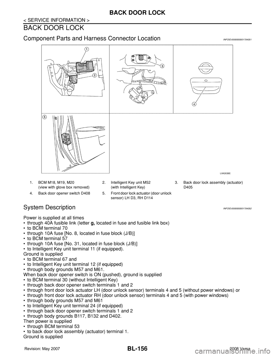
Component Parts and Harness Connector LocationINFOID:0000000001704051
System DescriptionINFOID:0000000001704052
Power is supplied at all times
• through 40A fusible link (letter g, located in fuse and fusible link box)
• to BCM terminal 70
• through 10A fuse [No. 8, located in fuse block (J/B)]
• to BCM terminal 57
• through 10A fuse [No. 31, located in fuse block (J/B)]
• to Intelligent Key unit terminal 11 (if equipped).
Ground is supplied
• to BCM terminal 67 and
• to Intelligent Key unit terminal 12 (if equipped)
• through body grounds M57 and M61.
When back door opener switch is ON (pushed), ground is supplied
• to BCM terminal 30 (without Intelligent Key)
• through back door opener switch terminals 1 and 2
• through front door lock actuator LH (door unlock sensor) terminals 4 and 5 (without power windows) or
• through front door lock actuator RH (door unlock sensor) terminals 4 and 5 (with power windows)
• through body grounds M57 and M61
• to Intelligent Key unit terminal 24 (if equipped)
• through back door opener switch terminals 1 and 2
• through body grounds B117, B132 and D402.
Then power is supplied
• through BCM terminal 53
• to back door lock assembly (actuator) terminal 1.
Ground is supplied
LIIA2638E
1. BCM M18, M19, M20
(view with glove box removed)2. Intelligent Key unit M52
(with Intelligent Key)3. Back door lock assembly (actuator)
D405
4. Back door opener switch D408 5. Front door lock actuator (door unlock
sensor) LH D3, RH D114
Page 593 of 2771
BACK DOOR LOCK
BL-159
< SERVICE INFORMATION >
C
D
E
F
G
H
J
K
L
MA
B
BL
N
O
P
CONSULT-III Function (BCM)INFOID:0000000001704056
CONSULT-III can display each diagnostic item using the diagnostic test modes shown following.
CONSULT-III APPLICATION ITEMS
Data Monitor
* : With Intelligent Key system
** : Without Intelligent Key system
Active Test
Work FlowINFOID:0000000001704057
1. Check the symptom and customer's requests.
2. Understand the outline of system. Refer to BL-156, "
System Description".
3. Repair or replace any malfunctioning parts. Refer to BL-159, "
Trouble Diagnosis Chart by Symptom".
4. Does back door opener operate normally? If Yes, GO TO 5. If No, GO TO 3.
5. INSPECTION END
Trouble Diagnosis Chart by SymptomINFOID:0000000001704058
BCM
diagnostic test itemDiagnostic mode Description
Inspection by partWORK SUPPORTSupports inspections and adjustments. Commands are transmitted to the
BCM for setting the status suitable for required operation, input/output sig-
nals are received from the BCM and received date is displayed.
DATA MONITOR Displays BCM input/output data in real time.
ACTIVE TESTOperation of electrical loads can be checked by sending drive signal to
them.
SELF-DIAG RESULTS Displays BCM self-diagnosis results.
CAN DIAG SUPPORT MNTRThe result of transmit/receive diagnosis of CAN communication can be
read.
ECU PART NUMBER BCM part number can be read.
CONFIGURATION Performs BCM configuration read/write functions.
Monitor item Content
IGN ON SW Indicates [ON/OFF] condition of ignition switch.
KEYLESS TRUNK** This is displayed even when it is not equipped.
I-KEY TRUNK* Momentarily indicates [ON/OFF] condition of back door open signal from back door opener switch.
TRNK OPNR SW** Indicates [ON/OFF] condition of back door open signal from back door opener switch.
VEHICLE SPEED This is displayed even when it is not equipped.
Test item Content
TRUNK/BACK DOORThis test is able to check back door lock assembly (actuator) unlock operation.
Actuator opens back door lock assembly when “OPEN” on CONSULT-III screen is touched.
Symptom Diagnoses/service procedureReference
page
Back door opener does not operate.
(Without Intelligent Key or power windows)1. Check BCM power supply and ground circuit.BCS-15
2. Check back door opener switch circuit.BL-160
3. Check back door lock assembly (actuator) circuit.BL-166
4. Replace BCM.BCS-18
Page 594 of 2771
BL-160
< SERVICE INFORMATION >
BACK DOOR LOCK
BCM Power Supply and Ground Circuit
INFOID:0000000001704059
Refer to BCS-15, "BCM Power Supply and Ground Circuit Inspection".
Check Back Door Opener Switch Circuit (Without Intelligent Key or Power Windows)
INFOID:0000000001704060
1.CHECK BACK DOOR OPENER SWITCH SIGNAL 1
With CONSULT-III
1. Insure front door lock knob LH is turned to the UNLOCK position.
2. Check back door opener switch (“TRNK OPNR SW”) in “DATA MONITOR” mode with CONSULT-III.
Without CONSULT-III
1. Insure front door lock knob LH is turned to the UNLOCK position.
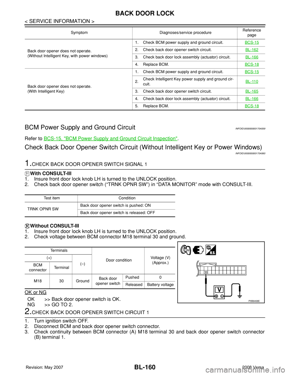
2. Check voltage between BCM connector M18 terminal 30 and ground.
OK or NG
OK >> Back door opener switch is OK.
NG >> GO TO 2.
2.CHECK BACK DOOR OPENER SWITCH CIRCUIT 1
1. Turn ignition switch OFF.
2. Disconnect BCM and back door opener switch connector.
3. Check continuity between BCM connector (A) M18 terminal 30 and back door opener switch connector
(B) terminal 1.
Back door opener does not operate.
(Without Intelligent Key, with power windows)1. Check BCM power supply and ground circuit.BCS-152. Check back door opener switch circuit.BL-162
3. Check back door lock assembly (actuator) circuit.BL-166
4. Replace BCM.BCS-18
Back door opener does not operate.
(With Intelligent Key)1. Check BCM power supply and ground circuit.BCS-15
2.Check Intelligent Key power supply and ground cir-
cuit.BL-110
3. Check back door opener switch circuit.BL-165
4. Check back door lock assembly (actuator) circuit.BL-166
5. Replace BCM.BCS-18
Symptom Diagnoses/service procedureReference
page
Test item Condition
TRNK OPNR SWBack door opener switch is pushed: ON
Back door opener switch is released: OFF
Te r m i n a l s
Door conditionVoltage (V)
(Approx.) (+)
(–)
BCM
connectorTe r m i n a l
M18 30 GroundBack door
opener switchPushed 0
Released Battery voltage
PIIB6468E