2008 NISSAN LATIO trunk release
[x] Cancel search: trunk releasePage 422 of 2771

BCS-6
< SERVICE INFORMATION >
BCM (BODY CONTROL MODULE)
• When CAN communication operation is detected, it switches to CAN communication status.
• When a state of the following switches changes, it switches to CAN communication state:
- Ignition switch
- Key switch (without Intelligent Key)
- Key switch and ignition knob switch (with Intelligent Key)
- Hazard switch
- Door lock/unlock switch
- Front door switch (LH, RH)
- Rear door switch (LH, RH)
- Back door lock assembly (Hatchback)
- Trunk key cylinder switch (Sedan)
- Trunk lamp switch and trunk release solenoid (Sedan)
- Combination switch (passing, lighting switch 1st position, front fog lamp)
- Keyfob (lock/unlock signal)
- Front door key cylinder switch LH
• When control performed only by BCM is required by switch, it shifts to CAN communication inactive
mode.
• Status of combination switch reading function is changed.
SYSTEMS CONTROLLED BY BCM DIRECTLY
• Power door lock system. Refer to BL-22 .
• Remote keyless entry system. Refer to BL-51
.
• Power window system. Refer to GW-18
. NOTE
• Sunroof system. Refer to RF-10. NOTE
• Room lamp timer. Refer to LT- 8 9 .
• Rear wiper and washer system. Refer to WW-24
.
NOTE:
Power supply only. No system control.
SYSTEMS CONTROLLED BY BCM AND IPDM E/R
• Panic system. Refer to BL-51 .
• Vehicle security (theft warning) system. Refer to BL-187
.
• NVIS(NATS) system. Refer to BL-210
.
• Headlamp, tail lamp and battery saver control systems. Refer to LT- 7 2
, LT- 4 or LT- 2 5 .
• Front fog lamp. Refer to LT- 3 9
.
• Front wiper and washer system. Refer to WW-3
.
• Rear window defogger system. Refer to GW-49
.
SYSTEMS CONTROLLED BY BCM AND COMBINATION METER
• Warning chime. Refer to DI-41 .
• Turn signal and hazard warning lamps. Refer to LT- 4 8
.
SYSTEMS CONTROLLED BY BCM AND INTELLIGENT KEY UNIT
• Intelligent Key system. Refer to BL-74 .
MAJOR COMPONENTS AND CONTROL SYSTEM
System Input Output
Remote keyless entry systemRemote keyless entry receiver
(keyfob)• All door locking actuators
• Turn signal lamp (LH, RH)
• Combination meter (turn signal lamp)
Intelligent Key system Intelligent Key unit• All door locking actuators
• Turn signal lamp (LH, RH)
• Combination meter (turn signal lamp)
Power door lock systemFront power door lock/unlock
switch (LH, RH)All door locking actuators
Power supply (IGN/RAP) to power
windowIgnition retained power supply Power supply to power window and sunroof system
Power supply (BAT) to power window Battery power supply Power supply to power window and sunroof system
Page 430 of 2771
BCS-14
< SERVICE INFORMATION >
BCM (BODY CONTROL MODULE)
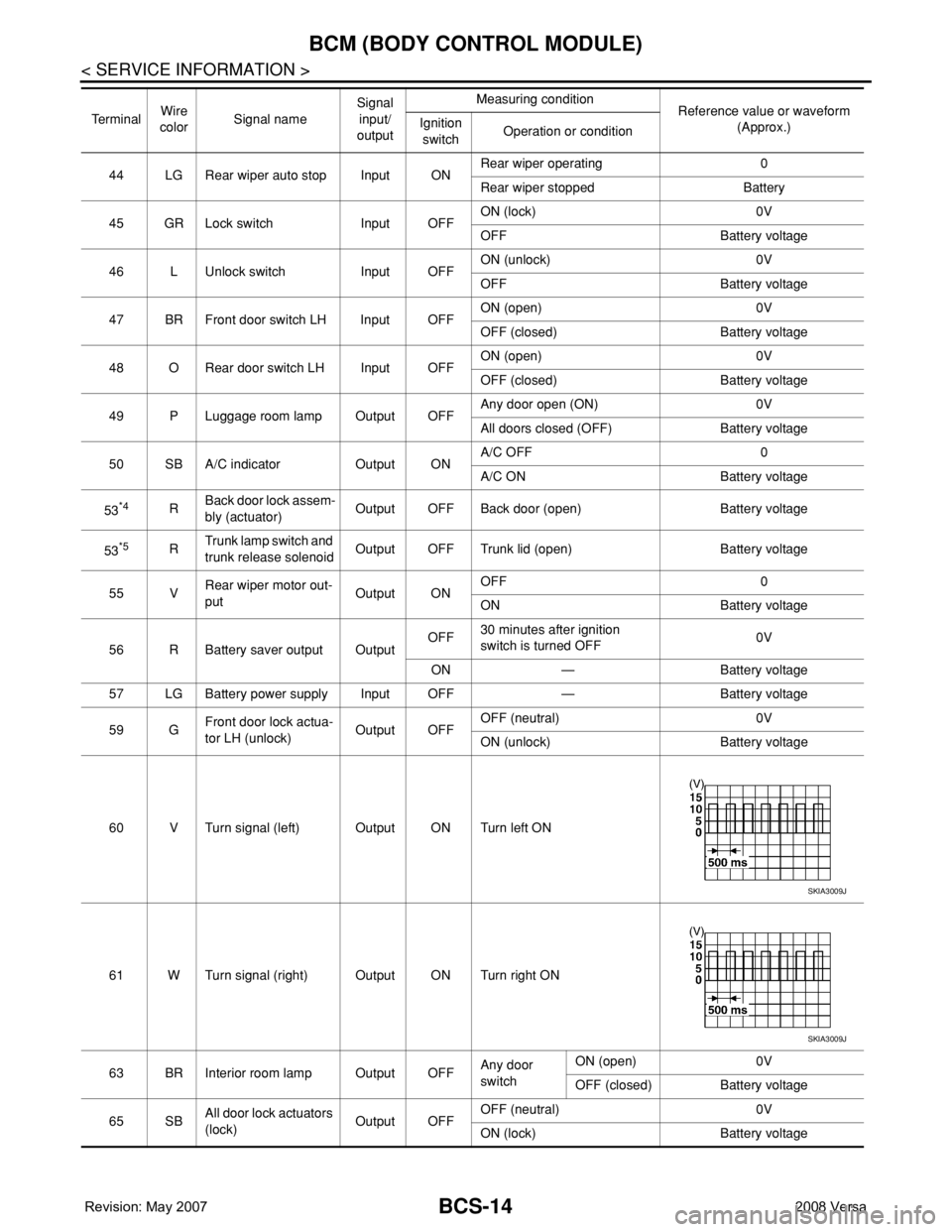
44 LG Rear wiper auto stop Input ONRear wiper operating 0
Rear wiper stopped Battery
45 GR Lock switch Input OFFON (lock) 0V
OFF Battery voltage
46 L Unlock switch Input OFFON (unlock) 0V
OFF Battery voltage
47 BR Front door switch LH Input OFFON (open) 0V
OFF (closed) Battery voltage
48 O Rear door switch LH Input OFFON (open) 0V
OFF (closed) Battery voltage
49 P Luggage room lamp Output OFFAny door open (ON) 0V
All doors closed (OFF) Battery voltage
50 SB A/C indicator Output ONA/C OFF 0
A/C ON Battery voltage
53
*4RBack door lock assem-
bly (actuator)Output OFF Back door (open) Battery voltage
53
*5RTrunk lamp switch and
trunk release solenoidOutput OFF Trunk lid (open) Battery voltage
55 VRear wiper motor out-
putOutput ONOFF 0
ON Battery voltage
56 R Battery saver output OutputOFF30 minutes after ignition
switch is turned OFF0V
ON — Battery voltage
57 LG Battery power supply Input OFF — Battery voltage
59 GFront door lock actua-
tor LH (unlock)Output OFFOFF (neutral) 0V
ON (unlock) Battery voltage
60 V Turn signal (left) Output ON Turn left ON
61 W Turn signal (right) Output ON Turn right ON
63 BR Interior room lamp Output OFFAny door
switchON (open) 0V
OFF (closed) Battery voltage
65 SBAll door lock actuators
(lock)Output OFFOFF (neutral) 0V
ON (lock) Battery voltage Te r m i n a lWire
colorSignal nameSignal
input/
outputMeasuring condition
Reference value or waveform
(Approx.) Ignition
switchOperation or condition
SKIA3009J
SKIA3009J
Page 436 of 2771

BL-2
ID Code Entry Procedure .......................................71
Keyfob Battery Replacement ..................................73
Removal and Installation of Remote Keyless Entry
Receiver .................................................................
73
INTELLIGENT KEY SYSTEM ............................74
Component Parts and Harness Connector Loca-
tion ..........................................................................
74
System Description .................................................76
CAN Communication System Description ..............83
Schematic ...............................................................84
Wiring Diagram - I/KEY - ........................................86
Intelligent Key Unit Harness Connector Terminal
Layout .....................................................................
96
Terminal and Reference Value for Intelligent Key
Unit .........................................................................
96
Steering Lock Solenoid Harness Connector Ter-
minal Layout ...........................................................
98
Terminal and Reference Value for Steering Lock
Solenoid ..................................................................
98
Terminal and Reference Value for BCM .................99
Trouble Diagnosis Procedure .................................99
CONSULT-III Functions (INTELLIGENT KEY) ......100
CONSULT-III Application Item ...............................101
Trouble Diagnosis Symptom Chart ........................103
CAN Communication System Inspection ...............109
Power Supply and Ground Circuit Inspection ........110
Key Switch (Intelligent Key Unit Input) Check .......110
Key Switch (BCM Input) Check .............................112
Ignition Knob Switch Check ...................................113
Door Switch Check (Hatchback) ............................114
Door Switch Check (Sedan) ..................................117
Door Request Switch Check ..................................118
Back Door Request Switch Check (Hatchback) ....120
Trunk Opener Request Switch Check (Sedan) .....122
Unlock Sensor Check ............................................124
Intelligent Key Warning Buzzer(s) Check ..............125
Outside Key Antenna (Driver Side and Passenger
Side) Check ...........................................................
126
Outside Key Antenna (Rear Bumper) Check .........128
Inside Key Antenna Check ....................................129
Steering Lock Solenoid Check ..............................131
Key Interlock Solenoid (With M/T) Check ..............133
Ignition Switch Position Check ..............................134
Stop Lamp Switch Check (With CVT) ....................134
Stop Lamp Switch Check (With M/T) .....................135
Check CVT Device (Park Position Switch) Check ..136
"P-SHIFT" Warning Lamp (With CVT) Check ........138
"LOCK" Warning Lamp (With M/T) Check .............138
"KEY" Warning Lamp (RED) Check ......................139
"KEY" Warning Lamp (GREEN) Check .................139
Check Warning Chime in Combination Meter ........140
Hazard Function Check .........................................140
Horn Function Check .............................................140
Headlamp Function Check ....................................141
Intelligent Key Battery Replacement .....................142
Remote Keyless Entry Function ............................142
Removal and Installation of Intelligent Key Unit ....142
DOOR ...............................................................144
Fitting Adjustment .................................................144
Removal and Installation .......................................147
FRONT DOOR LOCK .......................................150
Component Parts Location ...................................150
Removal and Installation .......................................150
REAR DOOR LOCK .........................................153
Component Parts Location ...................................153
Removal and Installation .......................................153
BACK DOOR LOCK .........................................156
Component Parts and Harness Connector Loca-
tion ........................................................................
156
System Description ...............................................156
Wiring Diagram - B/DOOR - ..................................157
Terminal and Reference Value for BCM ...............158
Terminal and Reference Value for Intelligent Key
Unit ........................................................................
158
CONSULT-III Function (BCM) ..............................159
Work Flow .............................................................159
Trouble Diagnosis Chart by Symptom ..................159
BCM Power Supply and Ground Circuit ................160
Check Back Door Opener Switch Circuit (Without
Intelligent Key or Power Windows) .......................
160
Check Back Door Opener Switch Circuit (Without
Intelligent Key, with Power Windows) ...................
162
Check Back Door Opener Switch Circuit (With In-
telligent Key) .........................................................
165
Check Back Door Lock Assembly (Actuator) Cir-
cuit ........................................................................
166
Removal and Installation .......................................168
TRUNK LID .......................................................170
Fitting Adjustment .................................................170
Trunk Lid Assembly ..............................................170
Trunk Lid Lock ......................................................171
Trunk Lid Striker ....................................................171
TRUNK LID OPENER .......................................173
Component Parts and Harness Connector Loca-
tion ........................................................................
173
System Description ...............................................173
Wiring Diagram - TLID - ........................................174
Terminal and Reference Value for BCM ...............175
Terminal and Reference Value for Intelligent Key
Unit ........................................................................
175
CONSULT-III Function (BCM) ..............................176
Work Flow .............................................................176
Trouble Diagnosis Chart by Symptom ..................176
BCM Power Supply and Ground Circuit ................177
Check Trunk Lid Opener Switch Circuit (Without
Intelligent Key or Power Windows) .......................
177
Check Trunk Lid Opener Switch Circuit (Without
Intelligent Key, with Power Windows) ...................
179
Check Trunk Lid Opener Switch Circuit (With Intel-
ligent Key) .............................................................
182
Check Trunk Release Solenoid Circuit .................183
Page 531 of 2771
INTELLIGENT KEY SYSTEM
BL-97
< SERVICE INFORMATION >
C
D
E
F
G
H
J
K
L
MA
B
BL
N
O
P
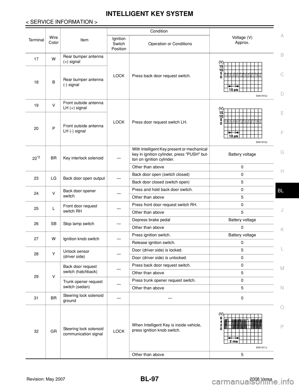
17 WRear bumper antenna
(+) signal
LOCK Press back door request switch.
18 BRear bumper antenna
(-) signal
19 VFront outside antenna
LH (+) signal
LOCK Press door request switch LH.
20 PFront outside antenna
LH (-) signal
22
*2BR Key interlock solenoid —With Intelligent Key present or mechanical
key in ignition cylinder, press "PUSH" but-
ton on ignition cylinder.Battery voltage
Other than above 0
23 LG Back door open output —Back door open (switch closed) 0
Back door closed (switch open) 5
24 VBack door opener
switch—Press and hold back door switch. 0
Other than above 5
25 LFront door request
switch RH—Press front door request switch RH. 0
Other than above 5
26 SB Stop lamp switch —Depress brake pedal Battery voltage
Other than above 0
27 W Ignition knob switch —Press ignition switch. Battery voltage
Release ignition switch. 0
28 YUnlock sensor
(driver side)—Door (driver side) is locked. 5
Door (driver side) is unlocked. 0
29 VBack door request
switch (hatchback)—Press back door request switch. 0
Other than above 5
Trunk opener request
switch (sedan)—Press trunk opener request switch. 0
Other than above 5
31 BRSteering lock solenoid
ground—— 0
32 GRSteering lock solenoid
communication signalLOCKWhen Intelligent Key is inside vehicle,
press ignition knob switch.
Other than above 5 TerminalWire
ColorItemCondition
Voltage (V)
Approx. Ignition
Switch
PositionOperation or Conditions
SIIA1910J
SIIA1910J
SIIA1911J
Page 556 of 2771
BL-122
< SERVICE INFORMATION >
INTELLIGENT KEY SYSTEM
OK or NG
OK >> GO TO 5.
NG >> Repair or replace back door request switch ground cir-
cuit.
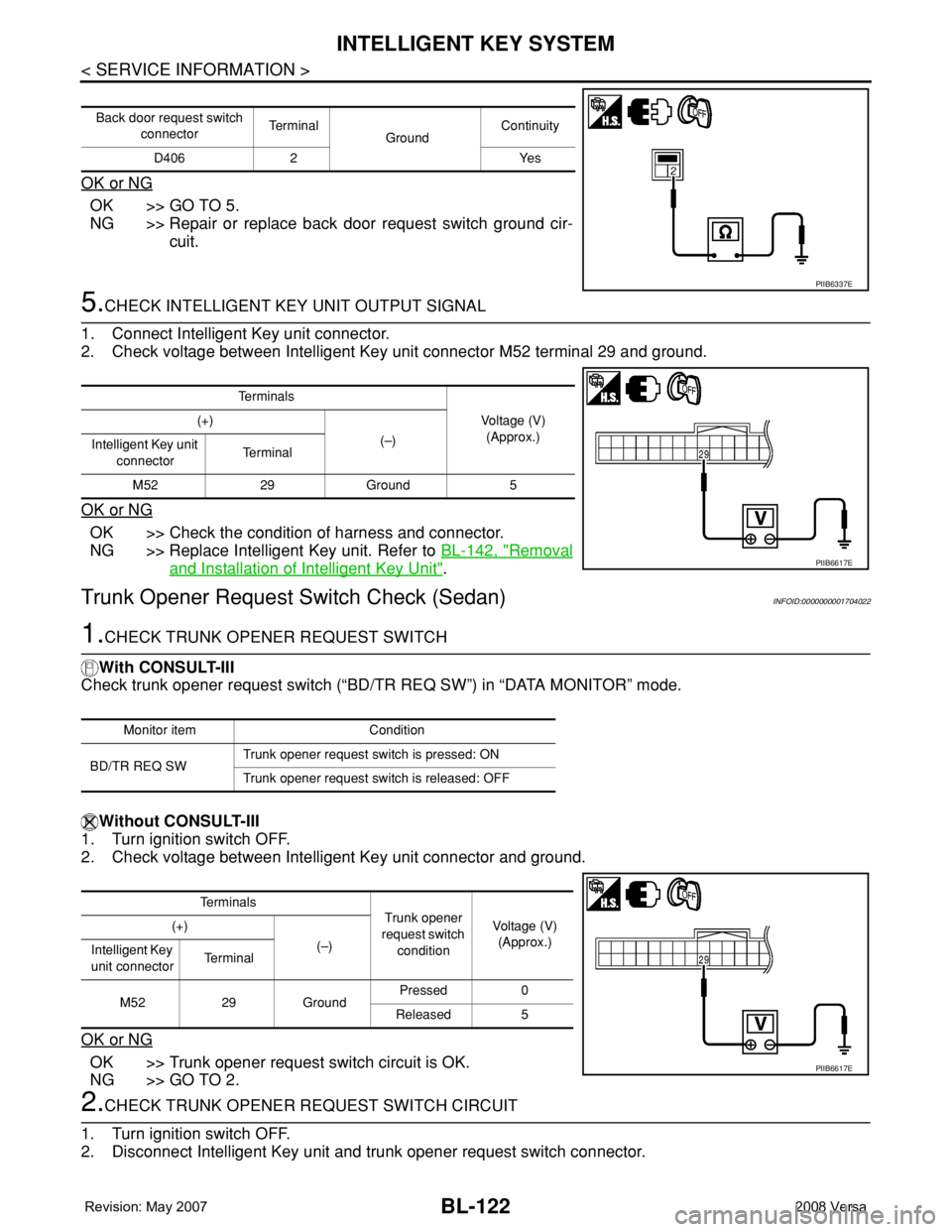
5.CHECK INTELLIGENT KEY UNIT OUTPUT SIGNAL
1. Connect Intelligent Key unit connector.
2. Check voltage between Intelligent Key unit connector M52 terminal 29 and ground.
OK or NG
OK >> Check the condition of harness and connector.
NG >> Replace Intelligent Key unit. Refer to BL-142, "
Removal
and Installation of Intelligent Key Unit".
Trunk Opener Request Switch Check (Sedan)INFOID:0000000001704022
1.CHECK TRUNK OPENER REQUEST SWITCH
With CONSULT-III
Check trunk opener request switch (“BD/TR REQ SW”) in “DATA MONITOR” mode.
Without CONSULT-III
1. Turn ignition switch OFF.
2. Check voltage between Intelligent Key unit connector and ground.
OK or NG
OK >> Trunk opener request switch circuit is OK.
NG >> GO TO 2.
2.CHECK TRUNK OPENER REQUEST SWITCH CIRCUIT
1. Turn ignition switch OFF.
2. Disconnect Intelligent Key unit and trunk opener request switch connector.
Back door request switch
connectorTe r m i n a l
GroundContinuity
D406 2 Yes
PIIB6337E
Te r m i n a l s
Voltage (V)
(Approx.) (+)
(–)
Intelligent Key unit
connectorTe r m i n a l
M52 29 Ground 5
PIIB6617E
Monitor item Condition
BD/TR REQ SWTrunk opener request switch is pressed: ON
Trunk opener request switch is released: OFF
Te r m i n a l s
Trunk opener
request switch
conditionVoltage (V)
(Approx.) (+)
(–)
Intelligent Key
unit connectorTe r m i n a l
M52 29 GroundPressed 0
Released 5
PIIB6617E
Page 557 of 2771
INTELLIGENT KEY SYSTEM
BL-123
< SERVICE INFORMATION >
C
D
E
F
G
H
J
K
L
MA
B
BL
N
O
P
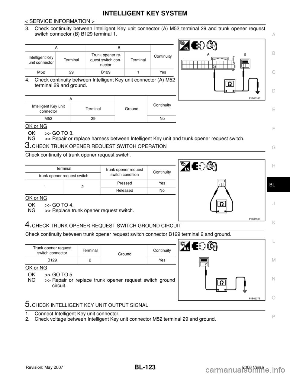
3. Check continuity between Intelligent Key unit connector (A) M52 terminal 29 and trunk opener request
switch connector (B) B129 terminal 1.
4. Check continuity between Intelligent Key unit connector (A) M52
terminal 29 and ground.
OK or NG
OK >> GO TO 3.
NG >> Repair or replace harness between Intelligent Key unit and trunk opener request switch.
3.CHECK TRUNK OPENER REQUEST SWITCH OPERATION
Check continuity of trunk opener request switch.
OK or NG
OK >> GO TO 4.
NG >> Replace trunk opener request switch.
4.CHECK TRUNK OPENER REQUEST SWITCH GROUND CIRCUIT
Check continuity between trunk opener request switch connector B129 terminal 2 and ground.
OK or NG
OK >> GO TO 5.
NG >> Repair or replace trunk opener request switch ground
circuit.
5.CHECK INTELLIGENT KEY UNIT OUTPUT SIGNAL
1. Connect Intelligent Key unit connector.
2. Check voltage between Intelligent Key unit connector M52 terminal 29 and ground.
AB
Continuity
Intelligent Key
unit connectorTe r m i n a l Trunk opener re-
quest switch con-
nectorTe r m i n a l
M52 29 B129 1 Yes
A
GroundContinuity
Intelligent Key unit
connectorTe r m i n a l
M52 29 No
PIIB6618E
Te r m i n a l
trunk opener request
switch conditionContinuity
trunk opener request switch
12Pressed Yes
Released No
PIIB6336E
Trunk opener request
switch connectorTe r m i n a l
GroundContinuity
B129 2 Yes
PIIB6337E
Page 600 of 2771
BL-166
< SERVICE INFORMATION >
BACK DOOR LOCK
OK or NG
OK >> GO TO 3.
NG >> Repair or replace harness.
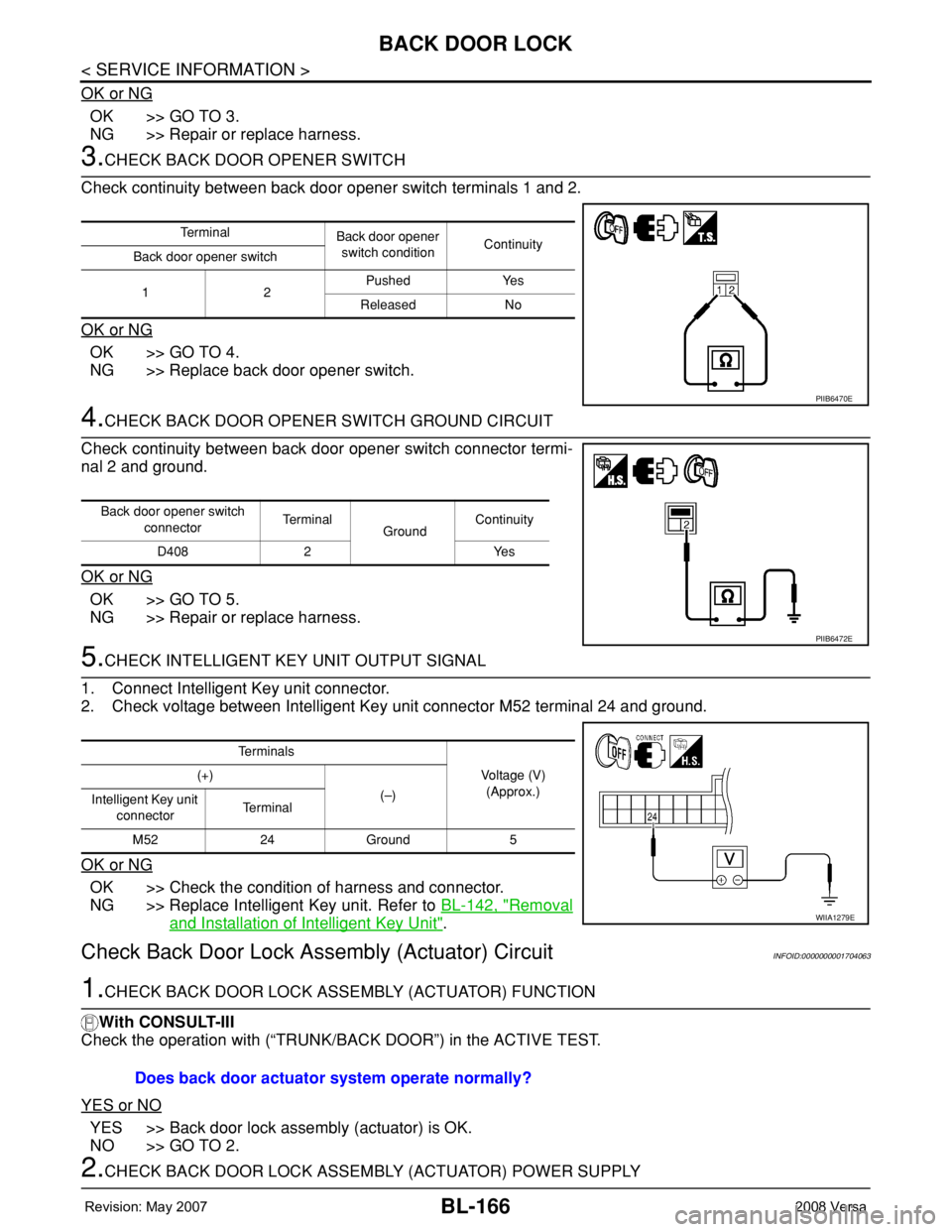
3.CHECK BACK DOOR OPENER SWITCH
Check continuity between back door opener switch terminals 1 and 2.
OK or NG
OK >> GO TO 4.
NG >> Replace back door opener switch.
4.CHECK BACK DOOR OPENER SWITCH GROUND CIRCUIT
Check continuity between back door opener switch connector termi-
nal 2 and ground.
OK or NG
OK >> GO TO 5.
NG >> Repair or replace harness.
5.CHECK INTELLIGENT KEY UNIT OUTPUT SIGNAL
1. Connect Intelligent Key unit connector.
2. Check voltage between Intelligent Key unit connector M52 terminal 24 and ground.
OK or NG
OK >> Check the condition of harness and connector.
NG >> Replace Intelligent Key unit. Refer to BL-142, "
Removal
and Installation of Intelligent Key Unit".
Check Back Door Lock Assembly (Actuator) CircuitINFOID:0000000001704063
1.CHECK BACK DOOR LOCK ASSEMBLY (ACTUATOR) FUNCTION
With CONSULT-III
Check the operation with (“TRUNK/BACK DOOR”) in the ACTIVE TEST.
YES or NO
YES >> Back door lock assembly (actuator) is OK.
NO >> GO TO 2.
2.CHECK BACK DOOR LOCK ASSEMBLY (ACTUATOR) POWER SUPPLY
Te r m i n a l
Back door opener
switch conditionContinuity
Back door opener switch
12Pushed Yes
Released No
PIIB6470E
Back door opener switch
connectorTe r m i n a l
GroundContinuity
D408 2 Yes
PIIB6472E
Te r m i n a l s
Voltage (V)
(Approx.) (+)
(–)
Intelligent Key unit
connectorTe r m i n a l
M52 24 Ground 5
WIIA1279E
Does back door actuator system operate normally?
Page 604 of 2771
BL-170
< SERVICE INFORMATION >
TRUNK LID
TRUNK LID
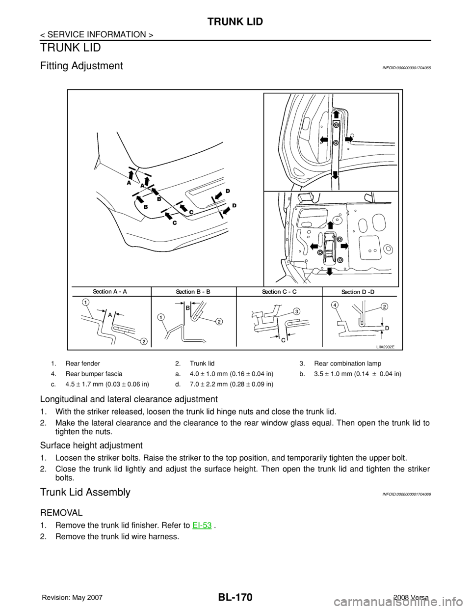
Fitting AdjustmentINFOID:0000000001704065
Longitudinal and lateral clearance adjustment
1. With the striker released, loosen the trunk lid hinge nuts and close the trunk lid.
2. Make the lateral clearance and the clearance to the rear window glass equal. Then open the trunk lid to
tighten the nuts.
Surface height adjustment
1. Loosen the striker bolts. Raise the striker to the top position, and temporarily tighten the upper bolt.
2. Close the trunk lid lightly and adjust the surface height. Then open the trunk lid and tighten the striker
bolts.
Trunk Lid AssemblyINFOID:0000000001704066
REMOVAL
1. Remove the trunk lid finisher. Refer to EI-53 .
2. Remove the trunk lid wire harness.
1. Rear fender 2. Trunk lid 3. Rear combination lamp
4. Rear bumper fascia a. 4.0 ± 1.0 mm (0.16 ± 0.04 in) b. 3.5 ± 1.0 mm (0.14 ± 0.04 in)
c. 4.5 ± 1.7 mm (0.03 ± 0.06 in) d. 7.0 ± 2.2 mm (0.28 ± 0.09 in)
LIIA2932E