Page 617 of 2771
TRUNK LID OPENER
BL-183
< SERVICE INFORMATION >
C
D
E
F
G
H
J
K
L
MA
B
BL
N
O
P
OK or NG
OK >> GO TO 3.
NG >> Repair or replace harness.
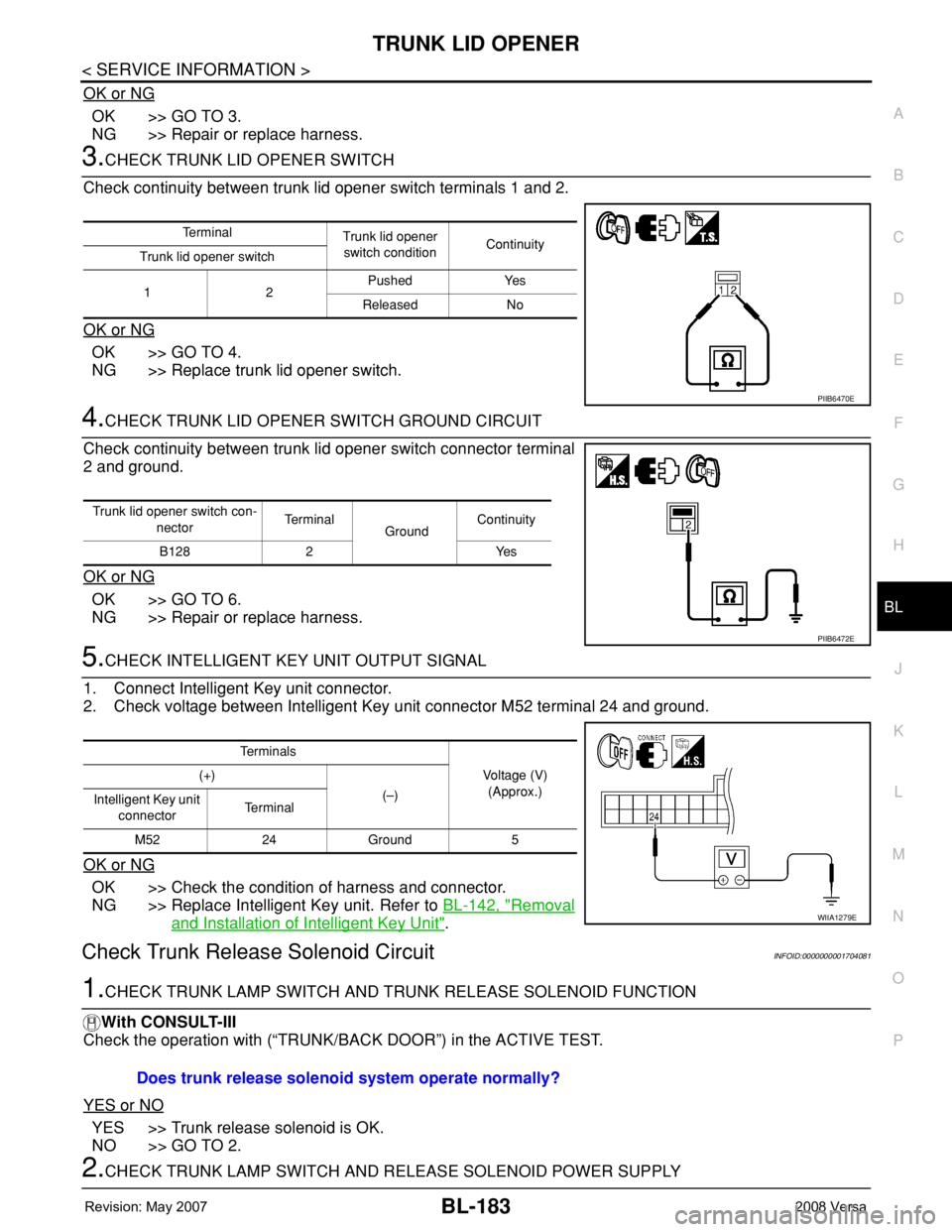
3.CHECK TRUNK LID OPENER SWITCH
Check continuity between trunk lid opener switch terminals 1 and 2.
OK or NG
OK >> GO TO 4.
NG >> Replace trunk lid opener switch.
4.CHECK TRUNK LID OPENER SWITCH GROUND CIRCUIT
Check continuity between trunk lid opener switch connector terminal
2 and ground.
OK or NG
OK >> GO TO 6.
NG >> Repair or replace harness.
5.CHECK INTELLIGENT KEY UNIT OUTPUT SIGNAL
1. Connect Intelligent Key unit connector.
2. Check voltage between Intelligent Key unit connector M52 terminal 24 and ground.
OK or NG
OK >> Check the condition of harness and connector.
NG >> Replace Intelligent Key unit. Refer to BL-142, "
Removal
and Installation of Intelligent Key Unit".
Check Trunk Release Solenoid CircuitINFOID:0000000001704081
1.CHECK TRUNK LAMP SWITCH AND TRUNK RELEASE SOLENOID FUNCTION
With CONSULT-III
Check the operation with (“TRUNK/BACK DOOR”) in the ACTIVE TEST.
YES or NO
YES >> Trunk release solenoid is OK.
NO >> GO TO 2.
2.CHECK TRUNK LAMP SWITCH AND RELEASE SOLENOID POWER SUPPLY
Te r m i n a l
Trunk lid opener
switch conditionContinuity
Trunk lid opener switch
12Pushed Yes
Released No
PIIB6470E
Trunk lid opener switch con-
nectorTe r m i n a l
GroundContinuity
B128 2 Yes
PIIB6472E
Te r m i n a l s
Voltage (V)
(Approx.) (+)
(–)
Intelligent Key unit
connectorTe r m i n a l
M52 24 Ground 5
WIIA1279E
Does trunk release solenoid system operate normally?
Page 618 of 2771
BL-184
< SERVICE INFORMATION >
TRUNK LID OPENER
1. Turn ignition switch OFF.
2. Insure both front door lock knobs are turned to the UNLOCK position.
3. Disconnect trunk lamp switch and trunk release solenoid connector.
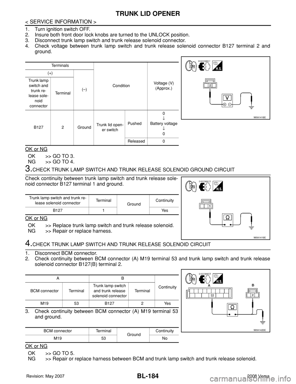
4. Check voltage between trunk lamp switch and trunk release solenoid connector B127 terminal 2 and
ground.
OK or NG
OK >> GO TO 3.
NG >> GO TO 4.
3.CHECK TRUNK LAMP SWITCH AND TRUNK RELEASE SOLENOID GROUND CIRCUIT
Check continuity between trunk lamp switch and trunk release sole-
noid connector B127 terminal 1 and ground.
OK or NG
OK >> Replace trunk lamp switch and trunk release solenoid.
NG >> Repair or replace harness.
4.CHECK TRUNK LAMP SWITCH AND TRUNK RELEASE SOLENOID CIRCUIT
1. Disconnect BCM connector.
2. Check continuity between BCM connector (A) M19 terminal 53 and trunk lamp switch and trunk release
solenoid connector B127(B) terminal 2.
3. Check continuity between BCM connector (A) M19 terminal 53
and ground.
OK or NG
OK >> GO TO 5.
NG >> Repair or replace harness between BCM and trunk lamp switch and trunk release solenoid.
Te r m i n a l s
ConditionVoltage (V)
(Approx.) (+)
(–) Trunk lamp
switch and
trunk re-
lease sole-
noid
connectorTe r m i n a l
B127 2 GroundTrunk lid open-
er switchPushed0
↓
Battery voltage
↓
0
Released 0
WIIA1418E
Trunk lamp switch and trunk re-
lease solenoid connectorTe r m i n a l
GroundContinuity
B127 1 Yes
WIIA1419E
AB
Continuity
BCM connector TerminalTrunk lamp switch
and trunk release
solenoid connectorTe r m i n a l
M19 53 B127 2 Yes
BCM connector Terminal
GroundContinuity
M19 53 No
WIIA1420E
Page 619 of 2771
TRUNK LID OPENER
BL-185
< SERVICE INFORMATION >
C
D
E
F
G
H
J
K
L
MA
B
BL
N
O
P
5.CHECK BCM OUTPUT SIGNAL
1. Connect BCM connector.
2. Check voltage between BCM connector M19 terminal 53 and ground.
OK or NG
OK >> Check the condition of harness and connector.
NG >> Replace BCM. Refer to BCS-18, "
Removal and Installation of BCM".
Te r m i n a l s
ConditionVoltage (V)
(Approx.) (+)
(–)
BCM
connectorTe r m i n a l
M19 53 GroundTrunk lid open-
er switchPushed0
↓
Battery voltage
↓
0
Released 0
PIIB6477E
Page 622 of 2771
BL-188
< SERVICE INFORMATION >
VEHICLE SECURITY (THEFT WARNING) SYSTEM
System Description
INFOID:0000000001704084
DESCRIPTION
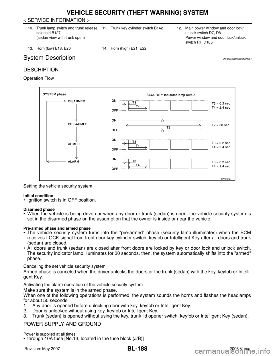
Operation Flow
Setting the vehicle security system
Initial condition• Ignition switch is in OFF position.
Disarmed phase• When the vehicle is being driven or when any door or trunk (sedan) is open, the vehicle security system is
set in the disarmed phase on the assumption that the owner is inside or near the vehicle.
Pre-armed phase and armed phase• The vehicle security system turns into the "pre-armed" phase (security lamp illuminates) when the BCM
receives LOCK signal from front door key cylinder switch, keyfob or Intelligent Key after all doors and trunk
(sedan) are closed.
• All doors and trunk (sedan) are closed after front doors are locked by key or door lock and unlock switch.
The security indicator lamp illuminates for 30 seconds. then, the system automatically shifts into the "armed"
phase.
Canceling the set vehicle security system
Armed phase is canceled when the driver unlocks the doors or the trunk (sedan) with the key, keyfob or Intelli-
gent Key.
Activating the alarm operation of the vehicle security system
Make sure the system is in the armed phase.
When one of the following operations is performed, the system sounds the horns and flashes the headlamps
for about 50 seconds.
1. Any door is opened before unlocking door with key, keyfob or Intelligent Key.
2. Door is unlocked without using key, keyfob or Intelligent Key.
3. Trunk (sedan) is opened without using the key, trunk lid opener switch, keyfob or Intelligent Key (sedan).
POWER SUPPLY AND GROUND
Power is supplied at all times• through 10A fuse [No.13, located in the fuse block (J/B)]
10. Trunk lamp switch and trunk release
solenoid B127
(sedan view with trunk open)11. Trunk key cylinder switch B142 12. Main power window and door lock/
unlock switch D7, D8
Power window and door lock/unlock
switch RH D105
13. Horn (low) E18, E20 14. Horn (high) E21, E22
PIIA1367E
Page 640 of 2771
BL-206
< SERVICE INFORMATION >
VEHICLE SECURITY (THEFT WARNING) SYSTEM
OK >> GO TO 3.
NG >> Repair or replace harness.
3.CHECK DOOR SWITCHES
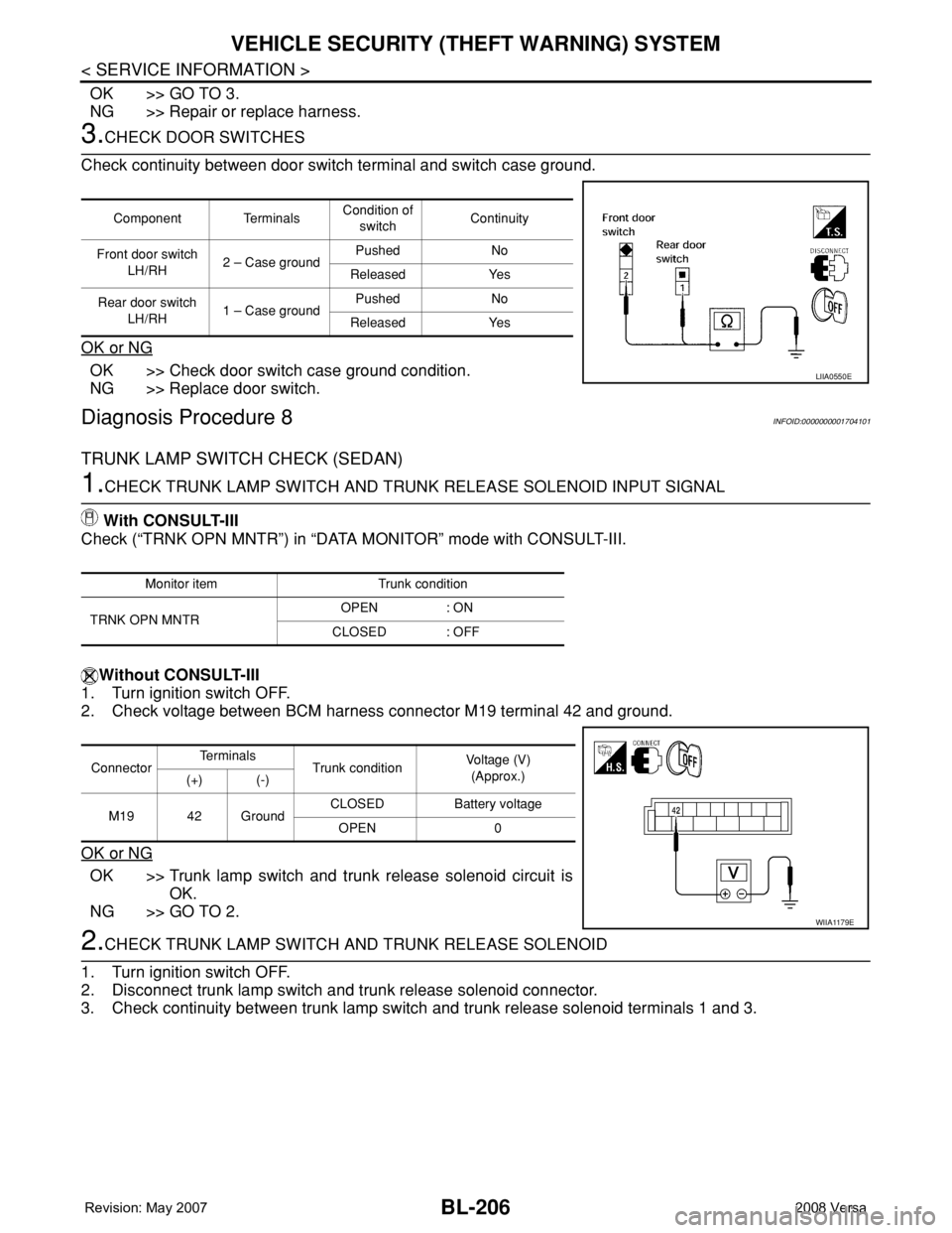
Check continuity between door switch terminal and switch case ground.
OK or NG
OK >> Check door switch case ground condition.
NG >> Replace door switch.
Diagnosis Procedure 8INFOID:0000000001704101
TRUNK LAMP SWITCH CHECK (SEDAN)
1.CHECK TRUNK LAMP SWITCH AND TRUNK RELEASE SOLENOID INPUT SIGNAL
With CONSULT-III
Check (“TRNK OPN MNTR”) in “DATA MONITOR” mode with CONSULT-III.
Without CONSULT-III
1. Turn ignition switch OFF.
2. Check voltage between BCM harness connector M19 terminal 42 and ground.
OK or NG
OK >> Trunk lamp switch and trunk release solenoid circuit is
OK.
NG >> GO TO 2.
2.CHECK TRUNK LAMP SWITCH AND TRUNK RELEASE SOLENOID
1. Turn ignition switch OFF.
2. Disconnect trunk lamp switch and trunk release solenoid connector.
3. Check continuity between trunk lamp switch and trunk release solenoid terminals 1 and 3.
Component TerminalsCondition of
switchContinuity
Front door switch
LH/RH2 – Case groundPushed No
Released Yes
Rear door switch
LH/RH1 – Case groundPushed No
Released Yes
LIIA0550E
Monitor item Trunk condition
TRNK OPN MNTROPEN : ON
CLOSED : OFF
ConnectorTe r m i n a l s
Trunk conditionVoltage (V)
(Approx.)
(+) (-)
M19 42 GroundCLOSED Battery voltage
OPEN 0
WIIA1179E
Page 641 of 2771
VEHICLE SECURITY (THEFT WARNING) SYSTEM
BL-207
< SERVICE INFORMATION >
C
D
E
F
G
H
J
K
L
MA
B
BL
N
O
P
OK or NG
OK >> GO TO 3.
NG >> Replace trunk lamp switch and trunk release solenoid.
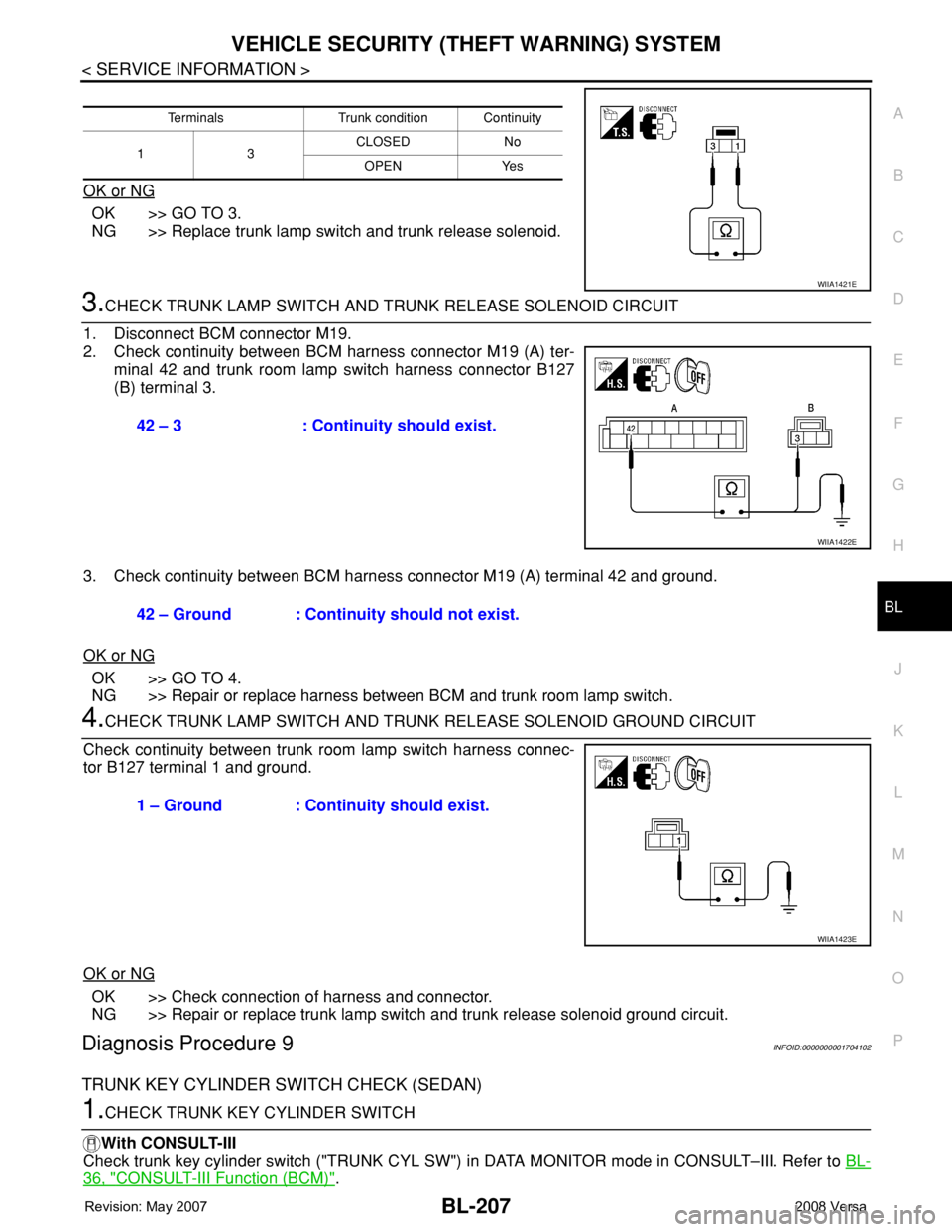
3.CHECK TRUNK LAMP SWITCH AND TRUNK RELEASE SOLENOID CIRCUIT
1. Disconnect BCM connector M19.
2. Check continuity between BCM harness connector M19 (A) ter-
minal 42 and trunk room lamp switch harness connector B127
(B) terminal 3.
3. Check continuity between BCM harness connector M19 (A) terminal 42 and ground.
OK or NG
OK >> GO TO 4.
NG >> Repair or replace harness between BCM and trunk room lamp switch.
4.CHECK TRUNK LAMP SWITCH AND TRUNK RELEASE SOLENOID GROUND CIRCUIT
Check continuity between trunk room lamp switch harness connec-
tor B127 terminal 1 and ground.
OK or NG
OK >> Check connection of harness and connector.
NG >> Repair or replace trunk lamp switch and trunk release solenoid ground circuit.
Diagnosis Procedure 9INFOID:0000000001704102
TRUNK KEY CYLINDER SWITCH CHECK (SEDAN)
1.CHECK TRUNK KEY CYLINDER SWITCH
With CONSULT-III
Check trunk key cylinder switch ("TRUNK CYL SW") in DATA MONITOR mode in CONSULT–III. Refer to BL-
36, "CONSULT-III Function (BCM)".
Terminals Trunk condition Continuity
13CLOSED No
OPEN Yes
WIIA1421E
42 – 3 : Continuity should exist.
WIIA1422E
42 – Ground : Continuity should not exist.
1 – Ground : Continuity should exist.
WIIA1423E
Page 1641 of 2771
EI-18
< ON-VEHICLE REPAIR >
REAR BUMPER
5. Pull the rear bumper fascia side outward and release the
bumper side bracket.
6. Remove rear bumper fascia upper clips and screws.
7. Release rear bumper upper retainer (1), then pull rear bumper
fascia outward away from rear of vehicle.
8. Disconnect license lamp connector.
9. Remove energy absorbing foam and rear bumper reinforcement.
10. Remove the bumper side bracket (1) RH/LH.
INSTALLATION
Installation is in the reverse order of removal.
Removal and Installation - SedanINFOID:0000000001704221
REMOVAL
1. Open trunk lid.
2. Remove rear combination lamp RH/LH. Refer to LT-86, "
Removal and Installation".
3. Remove rear bumper fascia spring nuts and screws RH/LH.
4. Remove rear fender protector. Refer to EI-23, "
Removal and Installation".
5. Pull the rear bumper fascia side outward and release the bumper side bracket.
6. Remove rear bumper fascia upper clips and screws.
LIIA2579E
LIIA2580E
LIIA2581E
Page 1653 of 2771
EI-30
< ON-VEHICLE REPAIR >
TRUNK LID FINISHER
TRUNK LID FINISHER
Removal and InstallationINFOID:0000000001704231
REMOVAL
1. Disconnect the negative and positive battery cables.
2. Open trunk lid, remove trunk lid finisher inner. Refer to EI-53
.
3. Remove trunk lid finisher outer nuts.
4. Release the clips, then pull trunk lid finisher outer away from trunk lid.
5. Disconnect trunk lid opener switch connector and trunk opener request switch connector, then remove
trunk lid finisher outer.
INSTALLATION
Installation is in the reverse order of removal.
1. Trunk lid finisher outer 2. Trunk lid opener switch connector 3. Trunk opener request switch connector
A. Clip C101
WIIA1413E