2008 NISSAN LATIO instrument panel
[x] Cancel search: instrument panelPage 1 of 2771

-1
QUICK REFERENCE INDEX
AGENERAL INFORMATIONGIGeneral Information
BENGINEEMEngine Mechanical
LUEngine Lubrication System
COEngine Cooling System
ECEngine Control System
FLFuel System
EXExhaust System
ACCAccelerator Control System
CTRANSMISSION/
TRANSAXLECLClutch System
MTManual Transaxle
ATAutomatic Transaxle
CVTCVT
DDRIVELINE/AXLEFAXFront Axle
RAXRear Axle
ESUSPENSIONFSUFront Suspension
RSURear Suspension
WTRoad Wheels & Tires
FBRAKESBRBrake System
PBParking Brake System
BRCBrake Control System
GSTEERINGPSPower Steering System
STCSteering Control System
HRESTRAINTSSBSeat Belts
SRSSupplemental Restraint System (SRS)
IBODYBLBody, Lock & Security System
GWGlasses, Window System & Mirrors
RFRoof
EIExterior & Interior
IPInstrument Panel
SESeat
JAIR CONDITIONERMTCManual Air Conditioner
KELECTRICALSCStarting & Charging System
LTLighting System
DIDriver Information System
WWWiper, Washer & Horn
BCSBody Control System
LANLAN System
AVAudio Visual, Navigation & Telephone System
ACSAuto Cruise Control System
PGPower Supply, Ground & Circuit Elements
LMAINTENANCEMAMaintenance
Edition: May 2007
Revision: May 2007
Publication No. SM8E-1C11U0
B
D
© 2007 NISSAN NORTH AMERICA, INC.
All rights reserved. No part of this Service Manual may be reproduced or stored in a retrieval system, or transmitted in any
form, or by any means, electronic, mechanical, photo-copying, recording or otherwise, without the prior written permission
of Nissan North America Inc.
A
C
E
F
G
H
I
J
K
L
M
Page 48 of 2771
AT-36
< SERVICE INFORMATION >
ON BOARD DIAGNOSTIC (OBD) SYSTEM
ON BOARD DIAGNOSTIC (OBD) SYSTEM
IntroductionINFOID:0000000001703172
A/T system has two self-diagnostic systems.
The first is emission-related on board diagnostic system (OBD-II) performed by the TCM in combination with
the ECM. The malfunction is indicated by the MIL (malfunction indicator lamp) and is stored as a DTC in the
ECM memory but not the TCM memory.
The second is the TCM original self-diagnosis indicated by the OD OFF indicator lamp. The malfunction is
stored in the TCM memory. The detected items are overlapped with OBD-II self-diagnostic items. For detail,
refer to AT-73, "
CONSULT-III Function (A/T)" .
OBD-II Function for A/T SystemINFOID:0000000001703173
The ECM provides emission-related on board diagnostic (OBD-II) functions for the A/T system. One function
is to receive a signal from the TCM used with OBD-related parts of the A/T system. The signal is sent to the
ECM when a malfunction occurs in the corresponding OBD-related part. The other function is to indicate a
diagnostic result by means of the MIL (malfunction indicator lamp) on the instrument panel. Sensors, switches
and solenoid valves are used as sensing elements.
The MIL automatically illuminates in One or Two Trip Detection Logic when a malfunction is sensed in relation
to A/T system parts.
One or Two Trip Detection Logic of OBD-IIINFOID:0000000001703174
ONE TRIP DETECTION LOGIC
If a malfunction is sensed during the first test drive, the MIL will illuminate and the malfunction will be stored in
the ECM memory as a DTC. The TCM is not provided with such a memory function.
TWO TRIP DETECTION LOGIC
When a malfunction is sensed during the first test drive, it is stored in the ECM memory as a 1st trip DTC
(diagnostic trouble code) or 1st trip freeze frame data. At this point, the MIL will not illuminate. — 1st trip
If the same malfunction as that experienced during the first test drive is sensed during the second test drive,
the MIL will illuminate. — 2nd trip
The “trip” in the “One or Two Trip Detection Logic” means a driving mode in which self-diagnosis is performed
during vehicle operation.
OBD-II Diagnostic Trouble Code (DTC)INFOID:0000000001703175
HOW TO READ DTC AND 1ST TRIP DTC
DTC and 1st trip DTC can be read by the following methods.
( with CONSULT-III or GST) CONSULT-III or GST (Generic Scan Tool) Examples: P0705, P0720 etc.
These DTC are prescribed by SAE J2012.
(CONSULT-III also displays the malfunctioning component or system.)
•1st trip DTC No. is the same as DTC No.
•Output of the diagnostic trouble code indicates that the indicated circuit has a malfunction. How-
ever, in case of the Mode II and GST, they do not indicate whether the malfunction is still occurring or
occurred in the past and returned to normal.
CONSULT-III can identify them as shown below, therefore, CONSULT-III (if available) is recom-
mended.
DTC or 1st trip DTC of a malfunction is displayed in SELF-DIAGNOSTIC RESULTS mode for “ENGINE” with
CONSULT-III. Time data indicates how many times the vehicle was driven after the last detection of a DTC.
If the DTC is being detected currently, the time data will be “0”.
If a 1st trip DTC is stored in the ECM, the time data will be “1t”.
Freeze Frame Data and 1st Trip Freeze Frame Data
The ECM has a memory function, which stores the driving condition such as fuel system status, calculated
load value, engine coolant temperature, short term fuel trim, long term fuel trim, engine speed and vehicle
speed at the moment the ECM detects a malfunction.
Page 50 of 2771

AT-38
< SERVICE INFORMATION >
ON BOARD DIAGNOSTIC (OBD) SYSTEM
1. If the ignition switch stays ON after repair work, be sure to turn ignition switch OFF once. Wait at least 10
seconds and then turn it ON (engine stopped) again.
2. Perform “TCM SELF-DIAGNOSTIC PROCEDURE (No Tools)”. Refer to AT-78, "
Diagnosis Procedure
without CONSULT-III" . (The engine warm-up step can be skipped when performing the diagnosis only to
erase the DTC.)
3. Perform “OBD-II SELF-DIAGNOSTIC PROCEDURE (No tools)”. Refer to EC-47, "
Emission-related Diag-
nostic Information" .
Malfunction Indicator Lamp (MIL)INFOID:0000000001703176
DESCRIPTION
The MIL is located on the instrument panel.
1. The MIL will light up when the ignition switch is turned ON with-
out the engine running. This is a bulb check.
• If the MIL does not light up, refer to DI-21
, or see EC-546 .
2. When the engine is started, the MIL should go off.
• If the MIL remains on, the on board diagnostic system has
detected an engine system malfunction.
SEF217U
Page 442 of 2771
BL-8
< SERVICE INFORMATION >
SQUEAK AND RATTLE TROUBLE DIAGNOSES
If the noise can be duplicated easily during the test drive, to help identify the source of the noise, try to dupli-
cate the noise with the vehicle stopped by doing one or all of the following:
1) Close a door.
2) Tap or push/pull around the area where the noise appears to be coming from.
3) Rev the engine.
4) Use a floor jack to recreate vehicle “twist”.
5) At idle, apply engine load (electrical load, half-clutch on M/T model, drive position on A/T model).
6) Raise the vehicle on a hoist and hit a tire with a rubber hammer.
• Drive the vehicle and attempt to duplicate the conditions the customer states exist when the noise occurs.
• If it is difficult to duplicate the noise, drive the vehicle slowly on an undulating or rough road to stress the
vehicle body.
CHECK RELATED SERVICE BULLETINS
After verifying the customer concern or symptom, check ASIST for Technical Service Bulletins (TSBs) related
to that concern or symptom.
If a TSB relates to the symptom, follow the procedure to repair the noise.
LOCATE THE NOISE AND IDENTIFY THE ROOT CAUSE
1. Narrow down the noise to a general area.To help pinpoint the source of the noise, use a listening tool
(Chassis Ear: J-39570, Engine Ear: J-39565 and mechanic's stethoscope).
2. Narrow down the noise to a more specific area and identify the cause of the noise by:
• removing the components in the area that you suspect the noise is coming from.
Do not use too much force when removing clips and fasteners, otherwise clips and fasteners can be broken
or lost during the repair, resulting in the creation of new noise.
• tapping or pushing/pulling the component that you suspect is causing the noise.
Do not tap or push/pull the component with excessive force, otherwise the noise will be eliminated only tem-
porarily.
• feeling for a vibration with your hand by touching the component(s) that you suspect is (are) causing the
noise.
• placing a piece of paper between components that you suspect are causing the noise.
• looking for loose components and contact marks.
Refer to BL-9, "
Generic Squeak and Rattle Troubleshooting".
REPAIR THE CAUSE
• If the cause is a loose component, tighten the component securely.
• If the cause is insufficient clearance between components:
- separate components by repositioning or loosening and retightening the component, if possible.
- insulate components with a suitable insulator such as urethane pads, foam blocks, felt cloth tape or urethane
tape. A NISSAN Squeak and Rattle Kit (J-43980) is available through your authorized NISSAN Parts Depart-
ment.
CAUTION:
Do not use excessive force as many components are constructed of plastic and may be damaged.
Always check with the Parts Department for the latest parts information.
The following materials are contained in the NISSAN Squeak and Rattle Kit (J-43980). Each item can be
ordered separately as needed.
URETHANE PADS [1.5 mm (0.059 in) thick]
Insulates connectors, harness, etc.
76268-9E005: 100×135 mm (3.94×5.31 in)/76884-71L01: 60×85 mm (2.36×3.35 in)/76884-71L02: 15×25
mm (0.59×0.98 in)
INSULATOR (Foam blocks)
Insulates components from contact. Can be used to fill space behind a panel.
73982-9E000: 45 mm (1.77 in) thick, 50×50 mm (1.97×1.97 in)/73982-50Y00: 10 mm (0.39 in) thick,
50×50 mm (1.97×1.97 in)
INSULATOR (Light foam block)
80845-71L00: 30 mm (1.18 in) thick, 30×50 mm (1.18×1.97 in)
FELT CLOTH TAPE
Used to insulate where movement does not occur. Ideal for instrument panel applications.
68370-4B000: 15×25 mm (0.59×0.98 in) pad/68239-13E00: 5 mm (0.20 in) wide tape roll. The following
materials not found in the kit can also be used to repair squeaks and rattles.
UHMW (TEFLON) TAPE
Insulates where slight movement is present. Ideal for instrument panel applications.
Page 443 of 2771
SQUEAK AND RATTLE TROUBLE DIAGNOSES
BL-9
< SERVICE INFORMATION >
C
D
E
F
G
H
J
K
L
MA
B
BL
N
O
P
SILICONE GREASE
Used instead of UHMW tape that will be visible or not fit.
Note: Will only last a few months.
SILICONE SPRAY
Use when grease cannot be applied.
DUCT TAPE
Use to eliminate movement.
CONFIRM THE REPAIR
Confirm that the cause of a noise is repaired by test driving the vehicle. Operate the vehicle under the same
conditions as when the noise originally occurred. Refer to the notes on the Diagnostic Worksheet.
Generic Squeak and Rattle TroubleshootingINFOID:0000000001703945
Refer to Table of Contents for specific component removal and installation information.
INSTRUMENT PANEL
Most incidents are caused by contact and movement between:
1. The cluster lid A and instrument panel
2. Acrylic lens and combination meter housing
3. Instrument panel to front pillar garnish
4. Instrument panel to windshield
5. Instrument panel mounting pins
6. Wiring harnesses behind the combination meter
7. A/C defroster duct and duct joint
These incidents can usually be located by tapping or moving the components to duplicate the noise or by
pressing on the components while driving to stop the noise. Most of these incidents can be repaired by apply-
ing felt cloth tape or silicone spray (in hard to reach areas). Urethane pads can be used to insulate wiring har-
ness.
CAUTION:
Do not use silicone spray to isolate a squeak or rattle. If you saturate the area with silicone, you will
not be able to recheck the repair.
CENTER CONSOLE
Components to pay attention to include:
1. Shifter assembly cover to finisher
2. A/C control unit and cluster lid C
3. Wiring harnesses behind audio and A/C control unit
The instrument panel repair and isolation procedures also apply to the center console.
DOORS
Pay attention to the:
1. Finisher and inner panel making a slapping noise
2. Inside handle escutcheon to door finisher
3. Wiring harnesses tapping
4. Door striker out of alignment causing a popping noise on starts and stops
Tapping or moving the components or pressing on them while driving to duplicate the conditions can isolate
many of these incidents. You can usually insulate the areas with felt cloth tape or insulator foam blocks from
the NISSAN Squeak and Rattle Kit (J-43980) to repair the noise.
TRUNK
Trunk noises are often caused by a loose jack or loose items put into the trunk by the owner.
In addition look for:
1. Trunk lid bumpers out of adjustment
2. Trunk lid striker out of adjustment
3. The trunk lid torsion bars knocking together
4. A loose license plate or bracket
Page 450 of 2771
BL-16
< SERVICE INFORMATION >
HOOD
Hood Lock Reinforcement
1. Remove front bumper. Refer to EI-14, "Removal and Installation".
2. Remove crash zone sensor. Refer to SRS-41, "
Removal and Installation".
3. Remove bolts, and the hood lock reinforcement.
Hood Lock Cable
1. Remove front grille (LH/RH). Refer to EI-20, "Removal and Installation".
2. Remove fender protector (LH). Refer to EI-23, "
Component".
3. Remove hood lock, and remove hood lock cable from hood lock.
4. Remove radiator core upper support, hood ledge, and then remove hood lock cable.
5. Remove hood opener on bottom left of instrument panel, and
then remove hood lock cable.
6. Remove grommet on lower dashboard, and pull out hood lock
cable from passenger room side.
CAUTION:
While pulling the cable, be careful not to damage (peel)
hood opener cable outer surface on edges of body through
hole.
INSTALLATION
Installation is in the reverse order of removal.
• Perform hood fitting adjustment. Refer to BL-13, "
Fitting Adjustment".
Hood Lock Reinforcement
When installing hood lock reinforcement, loosen hood bolts, and
then tighten bolts in the order as shown.
Hood Lock Cable
1. Pull the hood lock cable through the panel hole to the engine compartment.
CAUTION: 23.6 N·m (2.4 kg-m, 17 ft-lb)
PIIB6511E
LIIA2667E
23.6 N·m (2.4 kg-m, 17 ft-lb)
PIIB6513E
Page 456 of 2771
BL-22
< SERVICE INFORMATION >
POWER DOOR LOCK SYSTEM
POWER DOOR LOCK SYSTEM
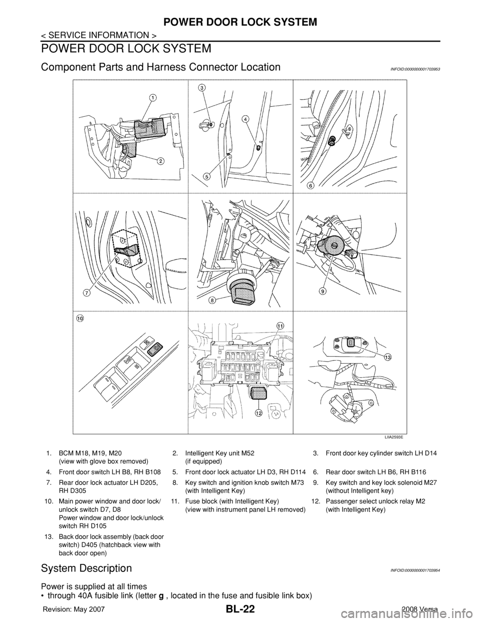
Component Parts and Harness Connector LocationINFOID:0000000001703953
System DescriptionINFOID:0000000001703954
Power is supplied at all times
• through 40A fusible link (letter g , located in the fuse and fusible link box)
LIIA2593E
1. BCM M18, M19, M20
(view with glove box removed)2. Intelligent Key unit M52
(if equipped)3. Front door key cylinder switch LH D14
4. Front door switch LH B8, RH B108 5. Front door lock actuator LH D3, RH D114 6. Rear door switch LH B6, RH B116
7. Rear door lock actuator LH D205,
RH D3058. Key switch and ignition knob switch M73
(with Intelligent Key)9. Key switch and key lock solenoid M27
(without Intelligent key)
10. Main power window and door lock/
unlock switch D7, D8
Power window and door lock/unlock
switch RH D10511. Fuse block (with Intelligent Key)
(view with instrument panel LH removed)12. Passenger select unlock relay M2
(with Intelligent Key)
13. Back door lock assembly (back door
switch) D405 (hatchback view with
back door open)
Page 509 of 2771
INTELLIGENT KEY SYSTEM
BL-75
< SERVICE INFORMATION >
C
D
E
F
G
H
J
K
L
MA
B
BL
N
O
P
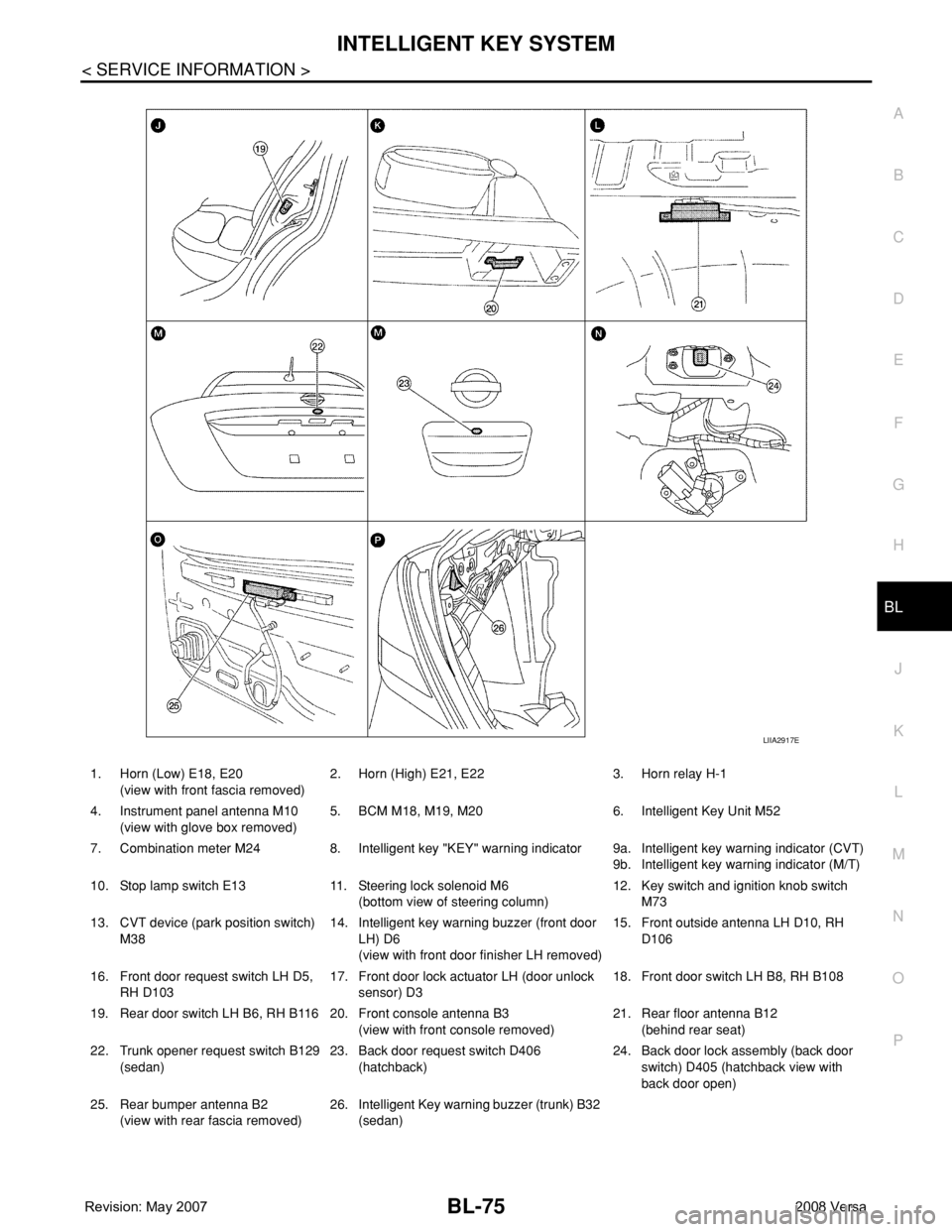
1. Horn (Low) E18, E20
(view with front fascia removed)2. Horn (High) E21, E22 3. Horn relay H-1
4. Instrument panel antenna M10
(view with glove box removed)5. BCM M18, M19, M20 6. Intelligent Key Unit M52
7. Combination meter M24 8. Intelligent key "KEY" warning indicator 9a.
9b.Intelligent key warning indicator (CVT)
Intelligent key warning indicator (M/T)
10. Stop lamp switch E13 11. Steering lock solenoid M6
(bottom view of steering column)12. Key switch and ignition knob switch
M73
13. CVT device (park position switch)
M3814. Intelligent key warning buzzer (front door
LH) D6
(view with front door finisher LH removed)15. Front outside antenna LH D10, RH
D106
16. Front door request switch LH D5,
RH D10317. Front door lock actuator LH (door unlock
sensor) D318. Front door switch LH B8, RH B108
19. Rear door switch LH B6, RH B116 20. Front console antenna B3
(view with front console removed)21. Rear floor antenna B12
(behind rear seat)
22. Trunk opener request switch B129
(sedan)23. Back door request switch D406
(hatchback)24. Back door lock assembly (back door
switch) D405 (hatchback view with
back door open)
25. Rear bumper antenna B2
(view with rear fascia removed)26. Intelligent Key warning buzzer (trunk) B32
(sedan)
LIIA2917E