2008 NISSAN LATIO instrument panel
[x] Cancel search: instrument panelPage 512 of 2771

BL-78
< SERVICE INFORMATION >
INTELLIGENT KEY SYSTEM
* : Hatchback
** : Sedan
KEY REMINDER FUNCTION
Key reminder functions have the following 2 functions.
CAUTION:
• The above function operates when the Intelligent Key is inside the vehicle. However, there may be
times when the Intelligent Key cannot be detected, and this function will not operate when the Intelli-
gent Key is on the instrument panel, rear parcel shelf or in the glove box. Also, this system some-
times does not operate if the Intelligent Key is in the door pocket of an open door.
List of Operation Related Parts
Parts marked with × are the parts related to operation
REMOTE KEYLESS ENTRY FUNCTIONS
The Intelligent Key has the same functions as the remote keyless entry system. Therefore, it can be used in
the same manner as the keyfob by operating the door lock/unlock button.
Door lock open function
Intelligent Key
Key switch
Ignition knob switch
Door switch
Back door lock assembly (back door switch)
*
Request switch (driver, passenger, back)
Door lock actuator
Inside key antenna
Outside key antenna
Intelligent Key warning buzzer (front door LH)
Intelligent Key warning buzzer (trunk)
**
Intelligent Key unit
CAN communication system
BCM
Hazard warning lamp
Door lock/unlock function by request switch××××××××××
Door lock/unlock function by mechanical key××
Hazard and buzzer reminder function××××××
Auto door lock function×××× × ×××
Key reminder function Operation condition Operation
Door is open to closeRight after all doors are closed under the following conditions.
• Intelligent Key is inside the vehicle
• Any door is opened
• All doors are locked by door lock and unlock switch or door
lock knob• All doors unlock operation
• Sound Intelligent Key warn-
ing buzzer for 3 seconds
Key reminder functions
Intelligent Key
Door switch
Unlock sensor
Door lock actuator
Inside key antenna
Intelligent Key warning buzzer(s)
Intelligent Key unit
CAN communication system
BCM
Any door open to close×××××××××
Page 530 of 2771
BL-96
< SERVICE INFORMATION >
INTELLIGENT KEY SYSTEM
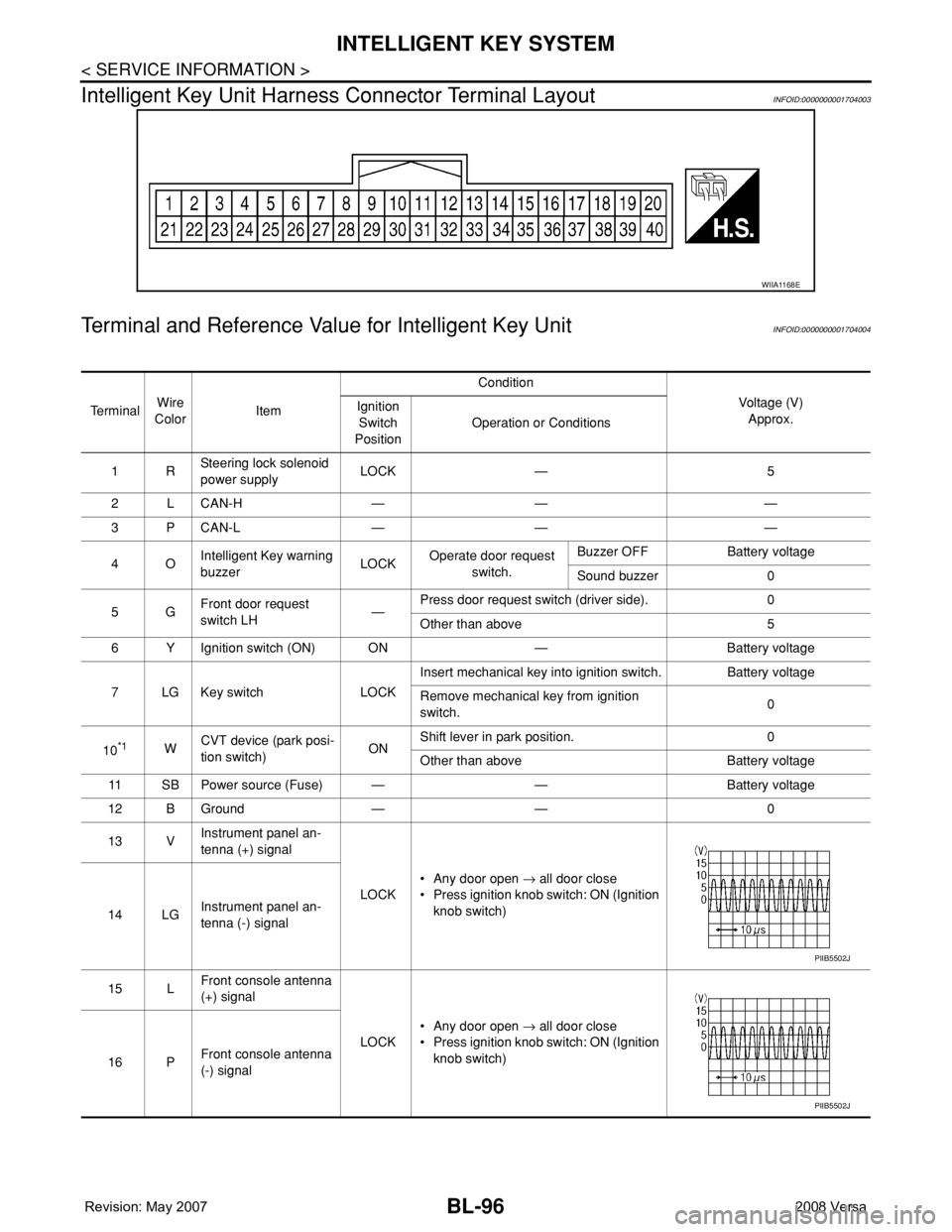
Intelligent Key Unit Harness Connector Terminal Layout
INFOID:0000000001704003
Terminal and Reference Value for Intelligent Key UnitINFOID:0000000001704004
WIIA1168E
Te r m i n a lWire
ColorItemCondition
Voltage (V)
Approx. Ignition
Switch
PositionOperation or Conditions
1RSteering lock solenoid
power supplyLOCK — 5
2 L CAN-H — — —
3 P CAN-L — — —
4OIntelligent Key warning
buzzerLOCKOperate door request
switch.Buzzer OFF Battery voltage
Sound buzzer 0
5GFront door request
switch LH—Press door request switch (driver side). 0
Other than above 5
6 Y Ignition switch (ON) ON — Battery voltage
7 LG Key switch LOCKInsert mechanical key into ignition switch. Battery voltage
Remove mechanical key from ignition
switch.0
10
*1WCVT device (park posi-
tion switch)ONShift lever in park position. 0
Other than above Battery voltage
11 SB Power source (Fuse) — — Battery voltage
12 B Ground — — 0
13 VInstrument panel an-
tenna (+) signal
LOCK• Any door open → all door close
• Press ignition knob switch: ON (Ignition
knob switch)
14 LGInstrument panel an-
tenna (-) signal
15 LFront console antenna
(+) signal
LOCK• Any door open → all door close
• Press ignition knob switch: ON (Ignition
knob switch)
16 PFront console antenna
(-) signal
PIIB5502J
PIIB5502J
Page 536 of 2771

BL-102
< SERVICE INFORMATION >
INTELLIGENT KEY SYSTEM
* : Sedan
WORK SUPPORT
Te s t i t e m D e s c r i p t i o n
DOOR LOCK/UNLOCKThis test is able to check door lock/unlock operation.
• The all door lock actuators are unlocked when “ALL UNLK” on CONSULT-III screen is touched.
• The all door lock actuators are locked when “LOCK” on CONSULT-III screen is touched.
ANTENNAThis test is able to check Intelligent Key antenna operation.
When the following conditions are met, hazard warning lamps flash.
• Inside key antenna (front console) detects Intelligent Key, when “ROOM ANT1” on CONSULT-
III screen is touched.
• Inside key antenna (instrument panel and rear floor) detects Intelligent Key, when “ROOM
ANT2” on CONSULT-III screen is touched.
• Outside key antenna (driver side) detects Intelligent Key, when “DRIVER ANT” on CONSULT-III
screen is touched.
• Outside key antenna (passenger side) detects Intelligent Key, when “ASSIST ANT” on CON-
SULT-III screen is touched.
• Outside key antenna (rear bumper) detects Intelligent Key, when “BK DOOR ANT” on CON-
SULT-III screen is touched.
OUTSIDE BUZZER(S)
(DRIVER DOOR), (TRUNK)
*This test is able to check Intelligent Key warning buzzer operation.
Intelligent Key warning buzzer sounds when “ON” on CONSULT-III screen is touched.
INSIDE BUZZER
(CHIME)This test is able to check Intelligent Key warning chime (Instrument panel) operation.
• Take away warning chime sounds when “TAKE OUT” on CONSULT-III screen is touched.
• Ignition switch warning chime sounds when “KNOB” on CONSULT-III screen is touched.
• Ignition key warning chime sounds when “KEY” on CONSULT-III screen is touched.
INDICATORThis test is able to check warning lamp operation.
• “KEY” Warning lamp (Green) illuminates when “BLUE ON” on CONSULT-III screen is touched.
• “KEY” Warning lamp (Red) illuminates when “RED ON” on CONSULT-III screen is touched.
• “LOCK” Warning lamp illuminates when “KNOB ON” on CONSULT-III screen is touched.
• “KEY” Warning lamp (Green) flashes when “BLUE IND” on CONSULT-III screen is touched.
• “KEY” Warning lamp (RED) flashes when “BLUE IND” on CONSULT-III screen is touched.
• “P-SHIFT” Warning lamp flashes when “KNOB ON” on CONSULT-III screen is touched.
Monitor item Description
CONFIRM KEY FOB ID It can be checked whether Intelligent Key ID code is registered or not in this mode.
TAKE OUT FROM WINDOW
WARNTake away warning chime (from window) mode can be changed to operate (ON) or not operate
(OFF) with this mode. The operation mode will be changed when “CHANGE SETT” on CONSULT-
III screen is touched.
LOW BAT OF KEY FOB WARNIntelligent Key low battery warning mode can be changed to operate (ON) or not operate (OFF)
with this mode. The operation mode will be changed when “CHANGE SETT” on CONSULT-III
screen is touched.
ANSWER BACK FUNCTIONBuzzer reminder function mode by Intelligent button can be changed to operate (ON) or not oper-
ate (OFF) with this mode. The operation mode will be changed when “CHANGE SETT” on CON-
SULT-III screen is touched.
SELECTIVE UNLOCK FUNC-
TIONSelective unlock function mode can be changed to operate (ON) or not operate (OFF) with this
mode. The operation mode will be changed when “CHANGE SETT” on CONSULT-III screen is
touched.
ANTI KEY LOCK IN FUNCTIONKey reminder function mode can be changed to operate (ON) or not operate (OFF) with this mode.
The operation mode will be changed when “CHANGE SETT” on CONSULT-III screen is touched.
HORN WITH KEYLESS LOCKHorn reminder function mode by Intelligent Key remote control button can be changed to operate
(ON) or not operate (OFF) with this mode. The operation mode will be changed when “CHANGE
SETT” on CONSULT-III screen is touched.
HAZARD ANSWER BACKHazard reminder function mode can be selected from the following with this mode. The operation
mode will be changed when “CHANGE SETT” on CONSULT-III screen is touched.
• LOCK ONLY: Door lock operation only
• UNLOCK ONLY: Door unlock operation only
• LOCK/UNLOCK: Lock/Unlock operation
• OFF: Non-operation
Page 564 of 2771
BL-130
< SERVICE INFORMATION >
INTELLIGENT KEY SYSTEM
OK or NG
OK >> Check the condition of harness and connector.
NG >> GO TO 2.
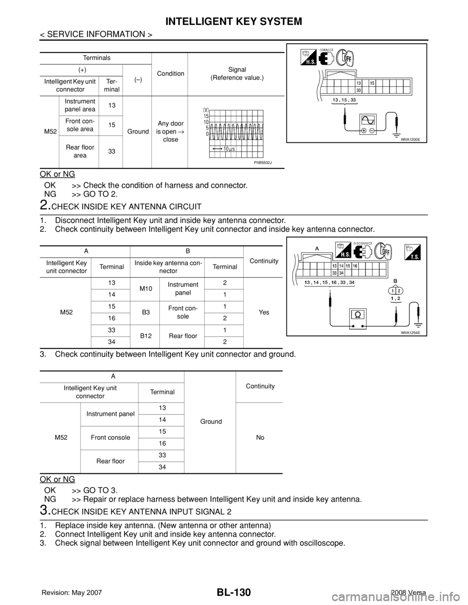
2.CHECK INSIDE KEY ANTENNA CIRCUIT
1. Disconnect Intelligent Key unit and inside key antenna connector.
2. Check continuity between Intelligent Key unit connector and inside key antenna connector.
3. Check continuity between Intelligent Key unit connector and ground.
OK or NG
OK >> GO TO 3.
NG >> Repair or replace harness between Intelligent Key unit and inside key antenna.
3.CHECK INSIDE KEY ANTENNA INPUT SIGNAL 2
1. Replace inside key antenna. (New antenna or other antenna)
2. Connect Intelligent Key unit and inside key antenna connector.
3. Check signal between Intelligent Key unit connector and ground with oscilloscope.
Te r m i n a l s
ConditionSignal
(Reference value.) (+)
(–)
Intelligent Key unit
connectorTe r -
minal
M52Instrument
panel area13
GroundAny door
is open →
close Front con-
sole area15
Rear floor
area33
WIIA1200E
PIIB5502J
AB
Continuity
Intelligent Key
unit connectorTe r m i n a lInside key antenna con-
nectorTe r m i n a l
M5213
M10Instrument
panel2
Ye s 14 1
15
B3Front con-
sole1
16 2
33
B12 Rear floor1
34 2
A
GroundContinuity
Intelligent Key unit
connectorTe r m i n a l
M52Instrument panel13
No 14
Front console15
16
Rear floor33
34
WIIA1254E
Page 565 of 2771
INTELLIGENT KEY SYSTEM
BL-131
< SERVICE INFORMATION >
C
D
E
F
G
H
J
K
L
MA
B
BL
N
O
P
OK or NG
OK >> Replace malfunction inside key antenna.
NG >> Replace Intelligent Key unit.
Steering Lock Solenoid CheckINFOID:0000000001704028
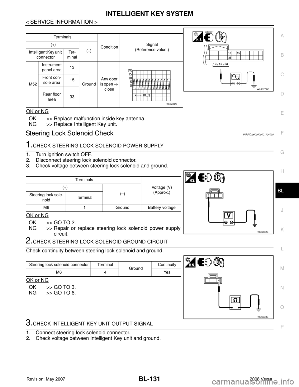
1.CHECK STEERING LOCK SOLENOID POWER SUPPLY
1. Turn ignition switch OFF.
2. Disconnect steering lock solenoid connector.
3. Check voltage between steering lock solenoid and ground.
OK or NG
OK >> GO TO 2.
NG >> Repair or replace steering lock solenoid power supply
circuit.
2.CHECK STEERING LOCK SOLENOID GROUND CIRCUIT
Check continuity between steering lock solenoid and ground.
OK or NG
OK >> GO TO 3.
NG >> GO TO 6.
3.CHECK INTELLIGENT KEY UNIT OUTPUT SIGNAL
1. Connect steering lock solenoid connector.
2. Check voltage between Intelligent Key unit and ground.
Te r m i n a l s
ConditionSignal
(Reference value.) (+)
(–)
Intelligent Key unit
connectorTe r -
minal
M52Instrument
panel area13
GroundAny door
is open →
close Front con-
sole area15
Rear floor
area33
WIIA1200E
PIIB5502J
Te r m i n a l s
Voltage (V)
(Approx.) (+)
(–)
Steering lock sole-
noidTe r m i n a l
M6 1 Ground Battery voltage
PIIB6632E
Steering lock solenoid connector Terminal
GroundContinuity
M6 4 Yes
PIIB6633E
Page 865 of 2771
CVT-26
< SERVICE INFORMATION >
ON BOARD DIAGNOSTIC (OBD) SYSTEM
ON BOARD DIAGNOSTIC (OBD) SYSTEM
IntroductionINFOID:0000000001703446
The CVT system has two self-diagnostic systems.
The first is the emission-related on board diagnostic system (OBD-II) performed by the TCM in combination
with the ECM. The malfunction is indicated by the MIL (malfunction indicator lamp) and is stored as a DTC in
the ECM memory, and the TCM memory.
The second is the TCM original self-diagnosis performed by the TCM. The malfunction is stored in the TCM
memory. The detected items are overlapped with OBD-II self-diagnostic items. For detail, refer to CVT-47,
"CONSULT-III Function (TRANSMISSION)".
OBD-II Function for CVT SystemINFOID:0000000001703447
The ECM provides emission-related on board diagnostic (OBD-II) functions for the CVT system. One function
is to receive a signal from the TCM used with OBD-related parts of the CVT system. The signal is sent to the
ECM when a malfunction occurs in the corresponding OBD-related part. The other function is to indicate a
diagnostic result by means of the MIL (malfunction indicator lamp) on the instrument panel. Sensors, switches
and solenoid valves are used as sensing elements.
The MIL automatically illuminates in One or Two Trip Detection Logic when a malfunction is sensed in relation
to CVT system parts.
One or Two Trip Detection Logic of OBD-IIINFOID:0000000001703448
ONE TRIP DETECTION LOGIC
If a malfunction is sensed during the first test drive, the MIL will illuminate and the malfunction will be stored in
the ECM memory as a DTC. The TCM is not provided with such a memory function.
TWO TRIP DETECTION LOGIC
When a malfunction is sensed during the first test drive, it is stored in the ECM memory as a 1st trip DTC
(diagnostic trouble code) or 1st trip freeze frame data. At this point, the MIL will not illuminate. — 1st trip
If the same malfunction as that experienced during the first test drive is sensed during the second test drive,
the MIL will illuminate. — 2nd trip
The “trip” in the “One or Two Trip Detection Logic” means a driving mode in which self-diagnosis is performed
during vehicle operation.
OBD-II Diagnostic Trouble Code (DTC)INFOID:0000000001703449
HOW TO READ DTC AND 1ST TRIP DTC
DTC and 1st trip DTC can be read by the following methods.
( with CONSULT-III or GST) CONSULT-III or GST (Generic Scan Tool) Examples: P0705, P0720 etc.
These DTC are prescribed by SAE J2012.
(CONSULT-III also displays the malfunctioning component or system.)
•1st trip DTC No. is the same as DTC No.
•Output of the diagnostic trouble code indicates that the indicated circuit has a malfunction. How-
ever, in case of the Mode II and GST, they do not indicate whether the malfunction is still occurring or
occurred in the past and returned to normal.
CONSULT-III can identify them as shown below, therefore, CONSULT-III (if available) is recom-
mended.
DTC or 1st trip DTC of a malfunction is displayed in SELF-DIAGNOSTIC RESULTS mode for “ENGINE” with
CONSULT-III. Time data indicates how many times the vehicle was driven after the last detection of a DTC.
If the DTC is being detected currently, the time data will be “0”.
If a 1st trip DTC is stored in the ECM, the time data will be “1t”.
Freeze Frame Data and 1st Trip Freeze Frame Data
Page 867 of 2771
CVT-28
< SERVICE INFORMATION >
ON BOARD DIAGNOSTIC (OBD) SYSTEM
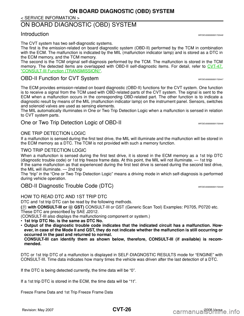
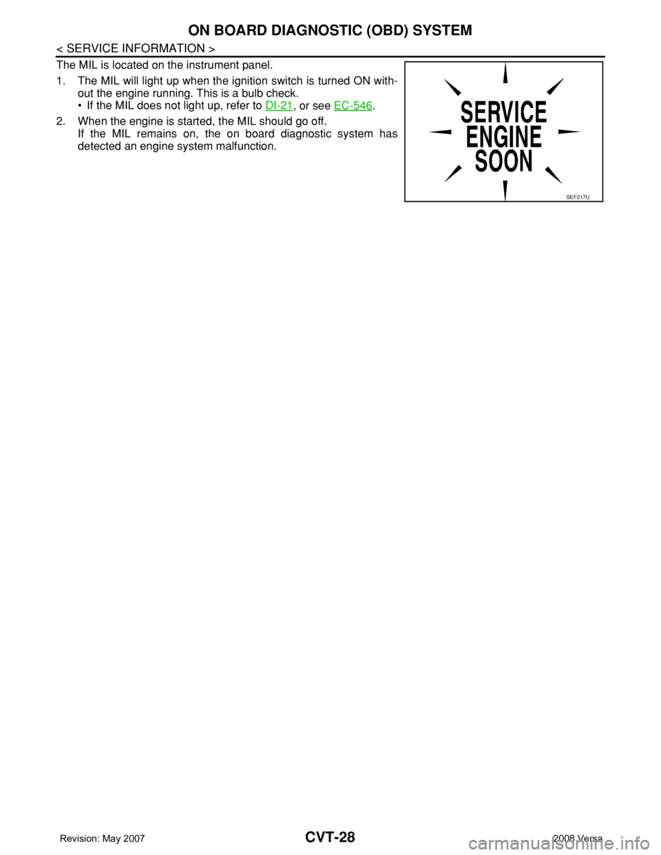
The MIL is located on the instrument panel.
1. The MIL will light up when the ignition switch is turned ON with-
out the engine running. This is a bulb check.
• If the MIL does not light up, refer to DI-21
, or see EC-546.
2. When the engine is started, the MIL should go off.
If the MIL remains on, the on board diagnostic system has
detected an engine system malfunction.
SEF217U
Page 1120 of 2771

EC-46
< SERVICE INFORMATION >
ON BOARD DIAGNOSTIC (OBD) SYSTEM
ON BOARD DIAGNOSTIC (OBD) SYSTEM
IntroductionINFOID:0000000001702573
The ECM has an on board diagnostic system, which detects malfunctions related to engine sensors or actua-
tors. The ECM also records various emission-related diagnostic information including:
The above information can be checked using procedures listed in the table below.
×: Applicable —: Not applicable
*: When DTC and 1st trip DTC simultaneously appear on the display, they cannot be clearly distinguished from each other.
The malfunction indicator lamp (MIL) on the instrument panel lights up when the same malfunction is detected
in two consecutive trips (Two trip detection logic), or when the ECM enters fail-safe mode.
(Refer to EC-87, "
Fail-Safe Chart".)
Two Trip Detection LogicINFOID:0000000001702574
When a malfunction is detected for the first time, 1st trip DTC and 1st trip Freeze Frame data are stored in the
ECM memory. The MIL will not light up at this stage. <1st trip>
If the same malfunction is detected again during the next drive, the DTC and Freeze Frame data are stored in
the ECM memory, and the MIL lights up. The MIL lights up at the same time when the DTC is stored. <2nd
trip> The “trip” in the “Two Trip Detection Logic” means a driving mode in which self-diagnosis is performed
during vehicle operation. Specific on board diagnostic items will cause the ECM to light up or blink the MIL,
and store DTC and Freeze Frame data, even in the 1st trip, as shown below.
×: Applicable —: Not applicable
When there is an open circuit on MIL circuit, the ECM cannot warn the driver by MIL lighting up when there is
malfunction on engine control system.
Emission-related diagnostic information Diagnostic service
Diagnostic Trouble Code (DTC) Service $03 of SAE J1979
Freeze Frame data Service $02 of SAE J1979
System Readiness Test (SRT) code Service $01 of SAE J1979
1st Trip Diagnostic Trouble Code (1st Trip DTC) Service $07 of SAE J1979
1st Trip Freeze Frame data
Test values and Test limits Service $06 of SAE J1979
Calibration ID Service $09 of SAE J1979
DTC 1st trip DTCFreeze Frame
data1st trip Freeze
Frame dataSRT code SRT status Test value
CONSULT-II××××××—
GST×× ×—×××
ECM××*———×—
ItemsMIL DTC 1st trip DTC
1st trip 2nd trip
1st trip
displaying2nd trip
displaying1st trip
displaying2nd trip
display-
ing BlinkingLighting
upBlinkingLighting
up
Misfire (Possible three way catalyst
damage) — DTC: P0300 - P0304 is
being detected×———— —×—
Misfire (Possible three way catalyst
damage) — DTC: P0300 - P0304 is
being detected——×——×——
One trip detection diagnoses
(Refer to EC-47, "
Emission-related
Diagnostic Information".)—×——×———
Except above — — —×—××—