2008 NISSAN LATIO change time
[x] Cancel search: change timePage 2 of 2771
-2
This manual contains maintenance and repair procedures for the
2008 NISSAN VERSA.
In order to assure your safety and the efficient functioning of the vehicle,
this manual should be read thoroughly. It is especially important that the
PRECAUTIONS in the GI section be completely understood before starting
any repair task.
All information in this manual is based on the latest product information
at the time of publication. The right is reserved to make changes in specifi-
cations and methods at any time without notice.
IMPORTANT SAFETY NOTICE
The proper performance of service is essential for both the safety of
the technician and the efficient functioning of the vehicle.
The service methods in this Service Manual are described in such a
manner that the service may be performed safely and accurately.
Service varies with the procedures used, the skills of the technician
and the tools and parts available. Accordingly, anyone using service
procedures, tools or parts which are not specifically recommended
by NISSAN must first be completely satisfied that neither personal
safety nor the vehicle’s safety will be jeopardized by the service
method selected.
Page 118 of 2771
AT-106
< SERVICE INFORMATION >
DTC P0731 A/T 1ST GEAR FUNCTION
5. Accelerate vehicle to 20 to 25 km/h (12 to 16 MPH) under the following conditions and release the accel-
erator pedal completely.
THROTTLE POSI: Less than 1.0/8 (at all times during step 4)
SLCT LVR POSI: “D” position
-Make sure that “GEAR” shows “2” after releasing pedal.
6. Depress accelerator pedal to WOT (more than 7.0/8 of “THROTTLE POSI”) quickly from a speed of 20 to
25 km/h (12 to 16 MPH) until “TESTING” changes to “STOP VEHICLE” or “COMPLETED”. (It will take
approximately 3 seconds.)
If the check result NG appears on CONSULT-III screen, go to AT-106, "
Diagnosis Procedure".
If “STOP VEHICLE” appears on CONSULT-III screen, go to the following step.
-Make sure that “GEAR” shows “1” when depressing accelerator pedal to WOT.
-If “TESTING” does not appear on CONSULT-III for a long time, select “SELF-DIAG RESULTS” for
“A/T”. In case a DTC other than “P0731 A/T 1ST GR FNCTN” is shown, refer to AT-73, "
CONSULT-III
Function (A/T)".
7. Stop vehicle.
8. Follow the instruction displayed. (Check for normal shifting referring to the table below.)
9. Make sure that “OK” is displayed. (If “NG” is displayed, refer to “Diagnostic Procedure”.)
Refer to AT-106, "
Diagnosis Procedure".
Refer to AT-61, "
Vehicle Speed at Which Gear Shifting Occurs".
WITH GST
Follow the procedure “WITH CONSULT-III”.
Diagnosis ProcedureINFOID:0000000001703235
1.CHECK VALVE RESISTANCE
1. Remove control valve assembly. Refer to AT-216, "
Control Valve Assembly and Accumulators".
- Shift solenoid valve A
- Shift solenoid valve B
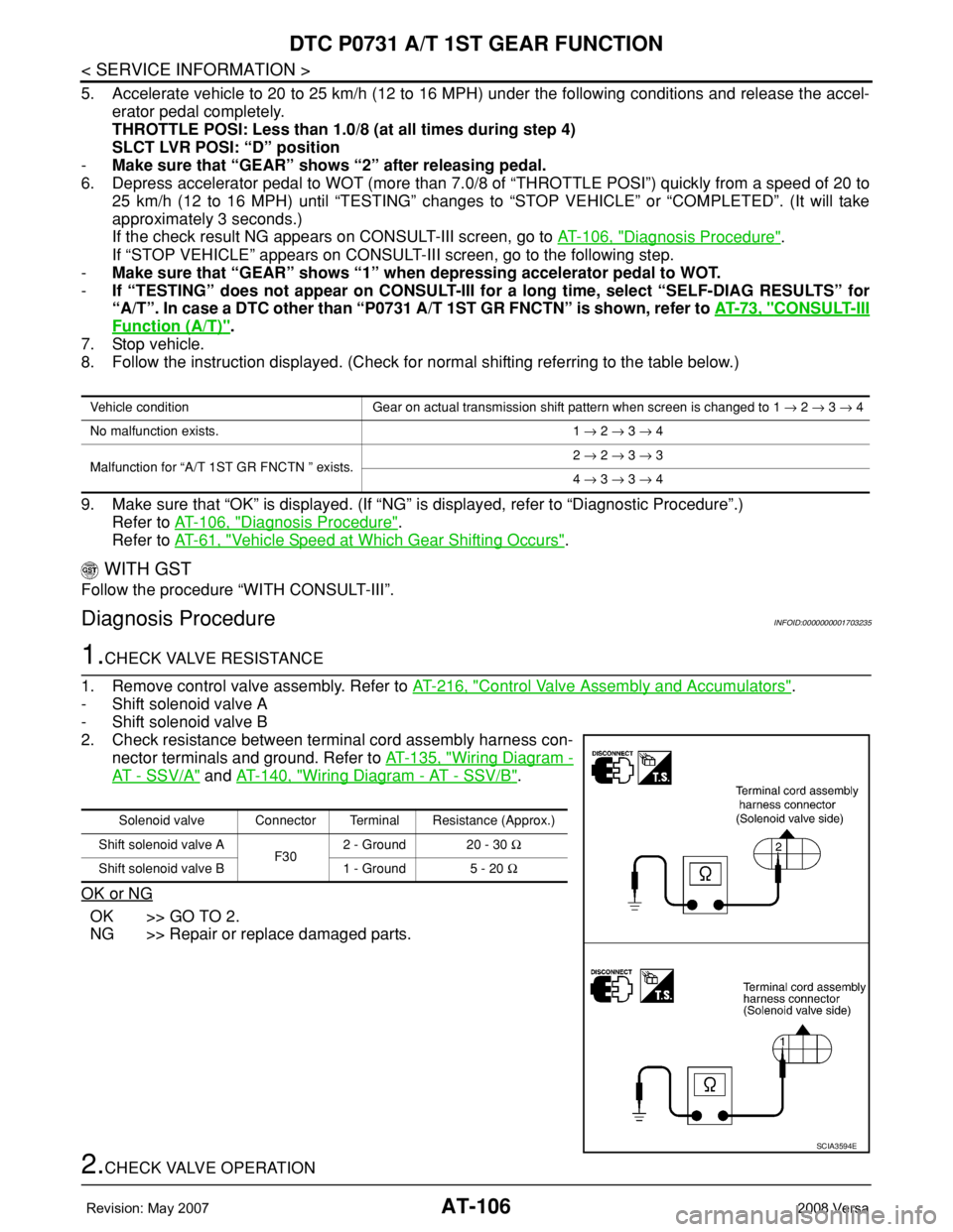
2. Check resistance between terminal cord assembly harness con-
nector terminals and ground. Refer to AT-135, "
Wiring Diagram -
AT - SSV/A" and AT-140, "Wiring Diagram - AT - SSV/B".
OK or NG
OK >> GO TO 2.
NG >> Repair or replace damaged parts.
2.CHECK VALVE OPERATION
Vehicle condition Gear on actual transmission shift pattern when screen is changed to 1 → 2 → 3 → 4
No malfunction exists. 1 → 2 → 3 → 4
Malfunction for “A/T 1ST GR FNCTN ” exists.2 → 2 → 3 → 3
4 → 3 → 3 → 4
Solenoid valve Connector Terminal Resistance (Approx.)
Shift solenoid valve A
F302 - Ground 20 - 30 Ω
Shift solenoid valve B 1 - Ground 5 - 20 Ω
SCIA3594E
Page 121 of 2771

DTC P0732 A/T 2ND GEAR FUNCTION
AT-109
< SERVICE INFORMATION >
D
E
F
G
H
I
J
K
L
MA
B
AT
N
O
P
-Make sure that “GEAR” shows “3” or “4” after releasing pedal.
6. Depress accelerator pedal to WOT (more than 7.0/8 of “THROTTLE POSI”) quickly from a speed of 45 to
50 km/h (28 to 31 MPH) until “TESTING” changes to “STOP VEHICLE” or “COMPLETE”. (It will take
approximately 3 seconds.)
If the check result NG appears on CONSULT-III screen, go to AT-109, "
Diagnosis Procedure".
If “STOP VEHICLE” appears on CONSULT-III screen, go to following step.
-Make sure that “GEAR” shows “2” when depressing accelerator pedal to WOT.
-If “TESTING” does not appear on CONSULT-III for a long time, select “SELF-DIAG RESULTS” for
“A/T”. In case a DTC other than “P0732 A/T 2ND GR FNCTN” is shown, refer to AT-73, "
CONSULT-
III Function (A/T)".
7. Stop vehicle.
8. Follow the instruction displayed. (Check for normal shifting referring to the table below.)
9. Make sure that “OK” is displayed. (If “NG” is displayed, refer to “Diagnostic Procedure”.)
Refer to AT-109, "
Diagnosis Procedure".
Refer to AT-61, "
Vehicle Speed at Which Gear Shifting Occurs".
WITH GST
Follow the procedure “WITH CONSULT-III”.
Diagnosis ProcedureINFOID:0000000001703240
1.CHECK VALVE RESISTANCE
1. Remove control valve assembly. Refer to AT-216, "
Control Valve Assembly and Accumulators".
- Shift solenoid valve B
2. Check resistance between terminal cord assembly harness con-
nector terminal and ground. Refer to AT-140, "
Wiring Diagram -
AT - SSV/B".
OK or NG
OK >> GO TO 2.
NG >> Repair or replace shift solenoid valve assembly.
2.CHECK VALVE OPERATION
1. Remove control valve assembly. Refer to AT-216, "
Control Valve Assembly and Accumulators".
- Shift solenoid valve B
2. Check solenoid valve by listening for its operating sound while
applying battery voltage to the terminal and ground. Refer to AT-
140, "Wiring Diagram - AT - SSV/B".
OK or NG
OK >> GO TO 3.
NG >> Repair or replace shift solenoid valve assembly.
3.CHECK CONTROL VALVE
1. Disassemble control valve assembly. Refer to AT-263, "
Control Valve Assembly".
2. Check to ensure that:
- Valve, sleeve and plug slide along valve bore under their own weight.
Vehicle condition Gear on actual transmission shift pattern when screen is changed to 1 → 2 → 3 → 4
No malfunction exists 1 → 2 → 3 → 4
Malfunction for “A/T 2ND GR FNCTN” exists. 4 → 3 → 3 → 4
Solenoid valve Connector Terminal Resistance (Approx.)
Shift solenoid valve B F30 1 - Ground 5 - 20 Ω
SCIA3454E
SCIA2058E
Page 124 of 2771
AT-112
< SERVICE INFORMATION >
DTC P0733 A/T 3RD GEAR FUNCTION
-Make sure that “GEAR” shows “4” after releasing pedal.
6. Depress accelerator pedal steadily with 3.5/8 - 4.5/8 of “THROTTLE POSI” from a speed of 60 to 75 km/h
(37 to 47 MPH) until “TESTING” changes to “STOP VEHICLE” or “COMPLETED”. (It will take approxi-
mately 3 seconds.)
If the check result NG appears on CONSULT-III screen, go to AT-112, "
Diagnosis Procedure".
If “STOP VEHICLE” appears on CONSULT-III screen, go to following step.
-Make sure that “GEAR” shows “3” when depressing accelerator pedal with 3.5/8 - 4.5/8 of
“THROTTLE POSI”.
-If “TESTING” does not appear on CONSULT-III for a long time, select “SELF-DIAG RESULTS” for
“A/T”. In case a DTC other than “P0733 A/T 3RD GR FNCTN” is shown, refer to AT-73, "
CONSULT-
III Function (A/T)".
7. Stop vehicle.
8. Follow the instruction displayed. (Check for normal shifting referring to the table below.)
9. Make sure that “OK” is displayed. (If “NG” is displayed, refer to “Diagnostic Procedure”.)
Refer to AT-112, "
Diagnosis Procedure".
Refer to AT-61, "
Vehicle Speed at Which Gear Shifting Occurs".
WITH GST
Follow the procedure “WITH CONSULT-III”.
Diagnosis ProcedureINFOID:0000000001703245
1.CHECK VALVE RESISTANCE
1. Remove control valve assembly. Refer to AT-216, "
Control Valve Assembly and Accumulators".
- Shift solenoid valve A
- Shift solenoid valve B
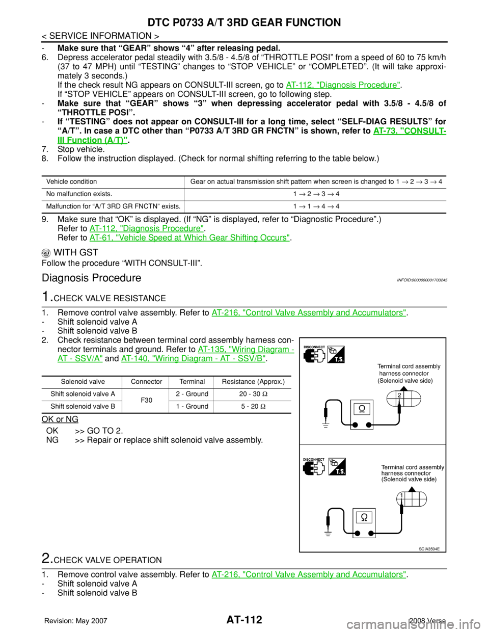
2. Check resistance between terminal cord assembly harness con-
nector terminals and ground. Refer to AT-135, "
Wiring Diagram -
AT - SSV/A" and AT-140, "Wiring Diagram - AT - SSV/B".
OK or NG
OK >> GO TO 2.
NG >> Repair or replace shift solenoid valve assembly.
2.CHECK VALVE OPERATION
1. Remove control valve assembly. Refer to AT-216, "
Control Valve Assembly and Accumulators".
- Shift solenoid valve A
- Shift solenoid valve B
Vehicle condition Gear on actual transmission shift pattern when screen is changed to 1 → 2 → 3 → 4
No malfunction exists. 1 → 2 → 3 → 4
Malfunction for “A/T 3RD GR FNCTN” exists. 1 → 1 → 4 → 4
Solenoid valve Connector Terminal Resistance (Approx.)
Shift solenoid valve A
F302 - Ground 20 - 30 Ω
Shift solenoid valve B 1 - Ground 5 - 20 Ω
SCIA3594E
Page 127 of 2771
DTC P0734 A/T 4TH GEAR FUNCTION
AT-115
< SERVICE INFORMATION >
D
E
F
G
H
I
J
K
L
MA
B
AT
N
O
P
WITH CONSULT-III
1. Start engine and select “DATA MONITOR” mode for “A/T” with CONSULT-III.
2. Touch “START”.
3. Make sure that output voltage of A/T fluid temperature sensor is within the range below.
FLUID TEMP SE: 0.4 - 1.5 V
If out of range, drive the vehicle to decrease the voltage (warm up the fluid) or stop engine to increase the
voltage (cool down the fluid).
4. Select “4TH GR FNCTN P0734” of “DTC WORK SUPPORT” mode for “A/T” with CONSULT-III and touch
“START”.
5. Accelerate vehicle to 55 to 65 km/h (34 to 40 MPH) under the following conditions and release the accel-
erator pedal completely.
THROTTLE POSI: Less than 5.5/8 (at all times during step 4)
SLCT LVR POSI: “D” position
-Make sure that “GEAR” shows “3” after releasing pedal.
6. Depress accelerator pedal steadily with 1.0/8 - 2.0/8 of “THROTTLE POSI” from a speed of 55 to 65 km/h
(34 to 40 MPH) until “TESTING” has turned to “STOP VEHICLE” or “COMPLETED”. (It will take approxi-
mately 3 seconds.)
If the check result NG appears on CONSULT-III screen, go to AT-115, "
Diagnosis Procedure".
If “STOP VEHICLE” appears on CONSULT-III screen, go to following step.
-Make sure that “GEAR” shows “4” when depressing accelerator pedal with 1.0/8 - 2.0/8 of
“THROTTLE POSI”.
-If “TESTING” does not appear on CONSULT-III for a long time, select “SELF-DIAG RESULTS” for
“A/T”. In case a DTC other than “P0734 A/T 4TH GR FNCTN” is shown, refer to AT-73, "
CONSULT-
III Function (A/T)".
7. Stop vehicle.
8. Follow the instruction displayed. (Check for normal shifting referring to the table below.)
9. Make sure that “OK” is displayed. (If “NG” is displayed, refer to “Diagnostic Procedure”.)
Refer to AT-115, "
Diagnosis Procedure".
Refer to AT-61, "
Vehicle Speed at Which Gear Shifting Occurs".
WITH GST
Follow the procedure “WITH CONSULT-III”.
Diagnosis ProcedureINFOID:0000000001703251
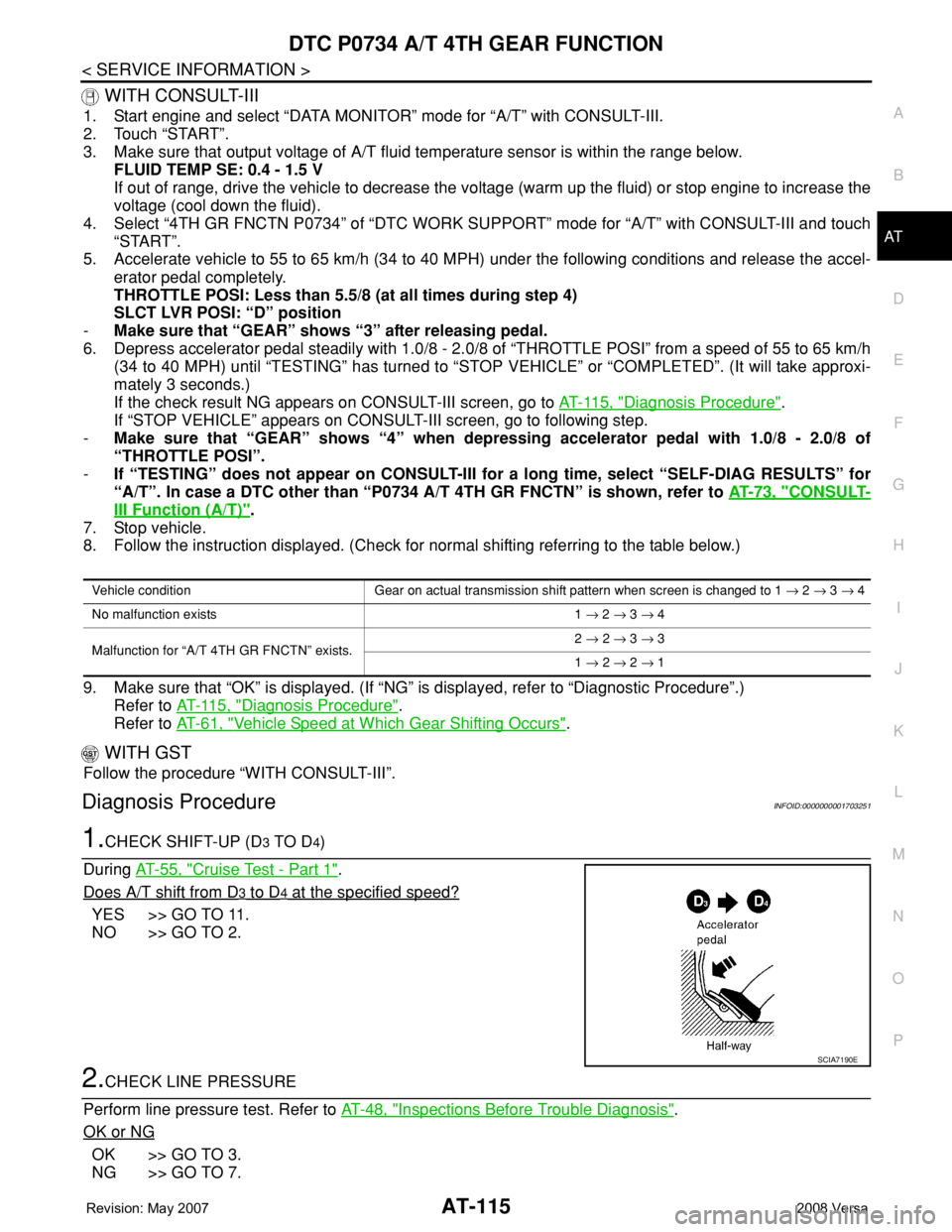
1.CHECK SHIFT-UP (D3 TO D4)
During AT-55, "
Cruise Test - Part 1".
Does A/T shift from D
3 to D4 at the specified speed?
YES >> GO TO 11.
NO >> GO TO 2.
2.CHECK LINE PRESSURE
Perform line pressure test. Refer to AT-48, "
Inspections Before Trouble Diagnosis".
OK or NG
OK >> GO TO 3.
NG >> GO TO 7.
Vehicle condition Gear on actual transmission shift pattern when screen is changed to 1 → 2 → 3 → 4
No malfunction exists 1 → 2 → 3 → 4
Malfunction for “A/T 4TH GR FNCTN” exists.2 → 2 → 3 → 3
1 → 2 → 2 → 1
SCIA7190E
Page 364 of 2771

AUDIO
AV-5
< SERVICE INFORMATION >
C
D
E
F
G
H
I
J
L
MA
B
AV
N
O
P
• to audio unit terminal 21 (with premium system)
• through body grounds M57 and M61 and
• to subwoofer terminal 3 (with premium system)
• through body grounds B7 and B19.
Then audio signals are supplied
• through audio unit terminals 2, 3, 4, 5, 11, 12, 13, and 14
• to terminals + and - of front door speaker LH and RH and
• to terminals + and - of tweeter LH and RH and
• to terminals + and - of rear door speaker LH and RH and
• to terminals 2 and 6 of subwoofer (with premium system).
Steering Wheel Audio Control Switches (with Bluetooth)
When one of steering wheel audio control switches is pushed, the resistance in steering switch circuit changes
depending on which button is pushed.
Satellite Radio Tuner (Pre-wiring)
The satellite radio tuner pre-wiring allows connection of a satellite radio tuner.
Power is supplied at all times
• through 20A fuse (No. 27, located in the fuse and fusible link box)
• to satellite radio tuner pre-wiring terminal 32.
With the ignition switch in the ACC or ON position, power is supplied
• through 10A fuse (No. 20, located in the fuse and fusible link box)
• to satellite radio tuner pre-wiring terminal 36.
Then audio signals are supplied
• through satellite radio tuner pre-wiring terminals 21, 22, 23 and 24
• to audio unit terminals 41, 42, 43 and 44.
Satellite Radio Tuner (Factory Installed)
Power is supplied at all times
• through 20A fuse (No. 27, located in the fuse and fusible link box)
• to satellite radio tuner terminal 32.
With the ignition switch in the ACC or ON position, power is supplied
• through 10A fuse (No. 20, located in the fuse and fusible link box)
• to satellite radio tuner terminal 36.
Ground is supplied through the case of the satellite radio tuner.
Then audio signals are supplied
• through satellite radio tuner terminals 21, 22, 23 and 24
• to audio unit terminals 41, 42, 43 and 44.
Ground is supplied through the case of the satellite radio tuner.
SPEED SENSITIVE VOLUME SYSTEM (MID LEVEL AND PREMIUM SYSTEM)
Volume level of this system goes up and down automatically in proportion to the vehicle speed. The control
level can be selected by the customer. Refer to Owner's Manual for operating instructions.
Page 380 of 2771
AUDIO
AV-21
< SERVICE INFORMATION >
C
D
E
F
G
H
I
J
L
MA
B
AV
N
O
P
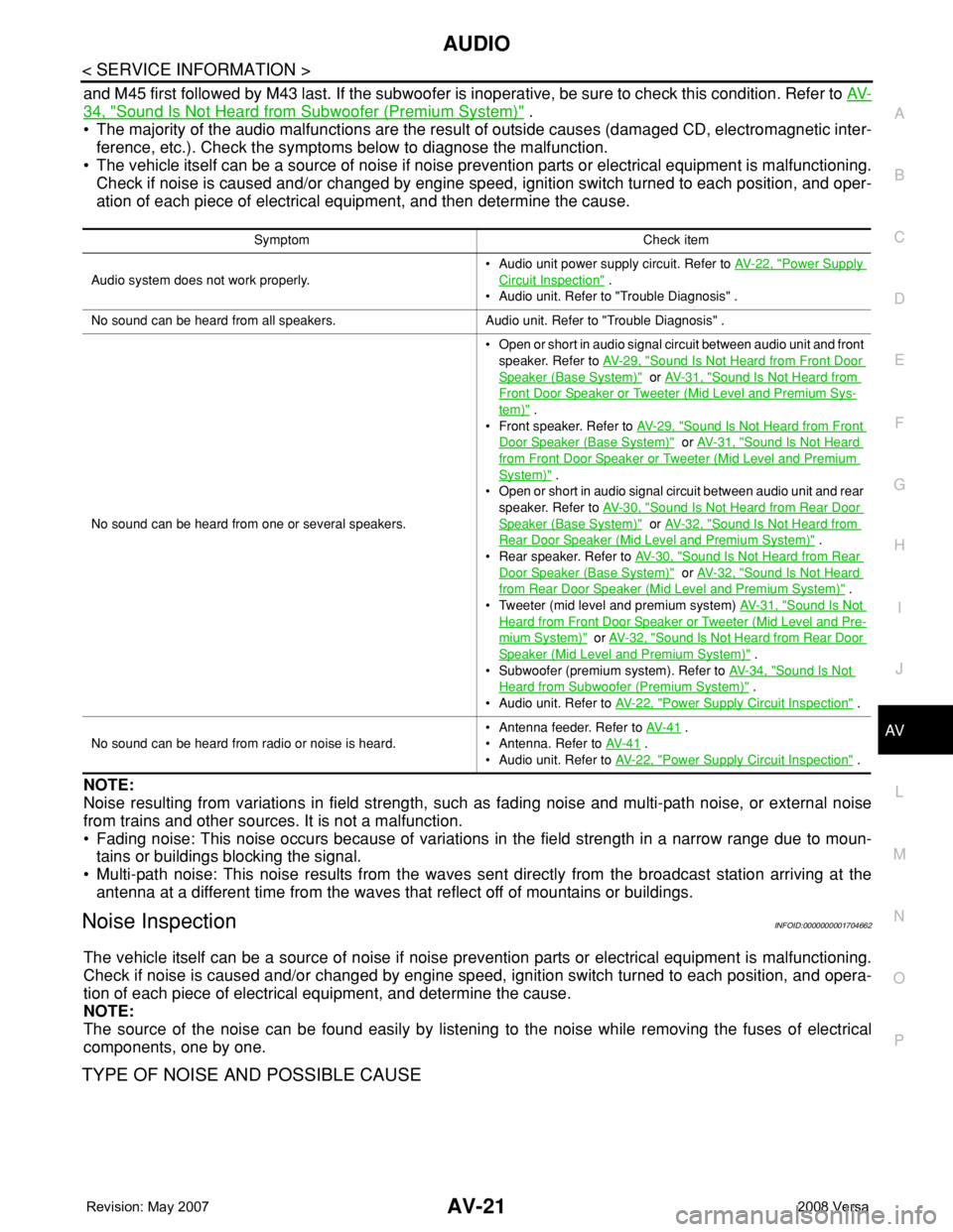
and M45 first followed by M43 last. If the subwoofer is inoperative, be sure to check this condition. Refer to AV-
34, "Sound Is Not Heard from Subwoofer (Premium System)" .
• The majority of the audio malfunctions are the result of outside causes (damaged CD, electromagnetic inter-
ference, etc.). Check the symptoms below to diagnose the malfunction.
• The vehicle itself can be a source of noise if noise prevention parts or electrical equipment is malfunctioning.
Check if noise is caused and/or changed by engine speed, ignition switch turned to each position, and oper-
ation of each piece of electrical equipment, and then determine the cause.
NOTE:
Noise resulting from variations in field strength, such as fading noise and multi-path noise, or external noise
from trains and other sources. It is not a malfunction.
• Fading noise: This noise occurs because of variations in the field strength in a narrow range due to moun-
tains or buildings blocking the signal.
• Multi-path noise: This noise results from the waves sent directly from the broadcast station arriving at the
antenna at a different time from the waves that reflect off of mountains or buildings.
Noise InspectionINFOID:0000000001704662
The vehicle itself can be a source of noise if noise prevention parts or electrical equipment is malfunctioning.
Check if noise is caused and/or changed by engine speed, ignition switch turned to each position, and opera-
tion of each piece of electrical equipment, and determine the cause.
NOTE:
The source of the noise can be found easily by listening to the noise while removing the fuses of electrical
components, one by one.
TYPE OF NOISE AND POSSIBLE CAUSE
Symptom Check item
Audio system does not work properly.• Audio unit power supply circuit. Refer to AV- 2 2 , "
Power Supply
Circuit Inspection" .
• Audio unit. Refer to "Trouble Diagnosis" .
No sound can be heard from all speakers. Audio unit. Refer to "Trouble Diagnosis" .
No sound can be heard from one or several speakers.• Open or short in audio signal circuit between audio unit and front
speaker. Refer to AV- 2 9 , "
Sound Is Not Heard from Front Door
Speaker (Base System)" or AV- 3 1 , "Sound Is Not Heard from
Front Door Speaker or Tweeter (Mid Level and Premium Sys-
tem)" .
• Front speaker. Refer to AV- 2 9 , "
Sound Is Not Heard from Front
Door Speaker (Base System)" or AV- 3 1 , "Sound Is Not Heard
from Front Door Speaker or Tweeter (Mid Level and Premium
System)" .
• Open or short in audio signal circuit between audio unit and rear
speaker. Refer to AV- 3 0 , "
Sound Is Not Heard from Rear Door
Speaker (Base System)" or AV- 3 2 , "Sound Is Not Heard from
Rear Door Speaker (Mid Level and Premium System)" .
• Rear speaker. Refer to AV- 3 0 , "
Sound Is Not Heard from Rear
Door Speaker (Base System)" or AV- 3 2 , "Sound Is Not Heard
from Rear Door Speaker (Mid Level and Premium System)" .
• Tweeter (mid level and premium system) AV- 3 1 , "
Sound Is Not
Heard from Front Door Speaker or Tweeter (Mid Level and Pre-
mium System)" or AV- 3 2 , "Sound Is Not Heard from Rear Door
Speaker (Mid Level and Premium System)" .
• Subwoofer (premium system). Refer to AV- 3 4 , "
Sound Is Not
Heard from Subwoofer (Premium System)" .
• Audio unit. Refer to AV- 2 2 , "
Power Supply Circuit Inspection" .
No sound can be heard from radio or noise is heard.• Antenna feeder. Refer to AV- 4 1
.
• Antenna. Refer to AV- 4 1
.
• Audio unit. Refer to AV- 2 2 , "
Power Supply Circuit Inspection" .
Page 403 of 2771

AV-44
< SERVICE INFORMATION >
TELEPHONE
tooth cellular telephones may not be recognized by the Bluetooth control unit. When a cellular telephone or
the Bluetooth control unit is replaced, the telephone must be paired with the Bluetooth control unit. Different
cellular telephones may have different pairing procedures. Refer to the cellular telephone operating manual.
Bluetooth Telephone System Diagram
Bluetooth Control Unit
When the ignition switch is turned to ACC or ON, the Bluetooth control unit will power up. During power up, the
Bluetooth control unit is initialized and performs various self checks. Initialization may take up to 10 seconds.
During this time the Bluetooth ON indicator will flash until initialization is complete. If a phone is present in the
vehicle and paired with the Bluetooth control unit, NISSAN Voice Recognition will then become active and the
Bluetooth ON indicator will remain on. Bluetooth telephone functions can be turned off using the NISSAN
Voice Recognition system. For Bluetooth control unit location, refer to AV-43, "
Component Parts and Harness
Connector Location".
Steering Wheel Audio Control Switches
When buttons on the steering wheel audio control switch are pushed, the resistance in steering wheel audio
control switch circuit changes depending on which button is pushed. The Bluetooth control module uses this
signal to perform various functions while navigating through the voice recognition system.
The following functions can be performed using the steering wheel audio control switch:
• Initiate Self Diagnosis of the Bluetooth telephone system
• Start a voice recognition session
• Answer and end telephone calls
• Adjust the volume of calls
• Record memos
Volume Switch
Call volume can be adjusted using the audio unit volume switch.
Bluetooth Microphone
The Bluetooth microphone is located in the roof console assembly. The Bluetooth microphone sends a signal
to the Bluetooth control unit. The Bluetooth microphone can be actively tested during self-diagnosis. For Blue-
tooth microphone location, refer to AV-43, "
Component Parts and Harness Connector Location".
Bluetooth ON Indicator
The Bluetooth ON indicator is located in the overhead console. The indicator will flash during power up while
the Bluetooth control unit is initializing. This process may take up to 10 seconds. If a phone is present in the
vehicle and paired with the Bluetooth control unit, the indicator will remain on to indicate that the system is
ready for voice commands. The indicator flashes during self-diagnosis. For Bluetooth ON indicator location,
refer to AV-43, "
Component Parts and Harness Connector Location".
Audio Unit
The audio unit receives signals from the Bluetooth control unit and sends audio signals to the speakers.
WKIA6001E