2008 NISSAN LATIO trunk
[x] Cancel search: trunkPage 363 of 2771
AV-4
< SERVICE INFORMATION >
AUDIO
AUDIO
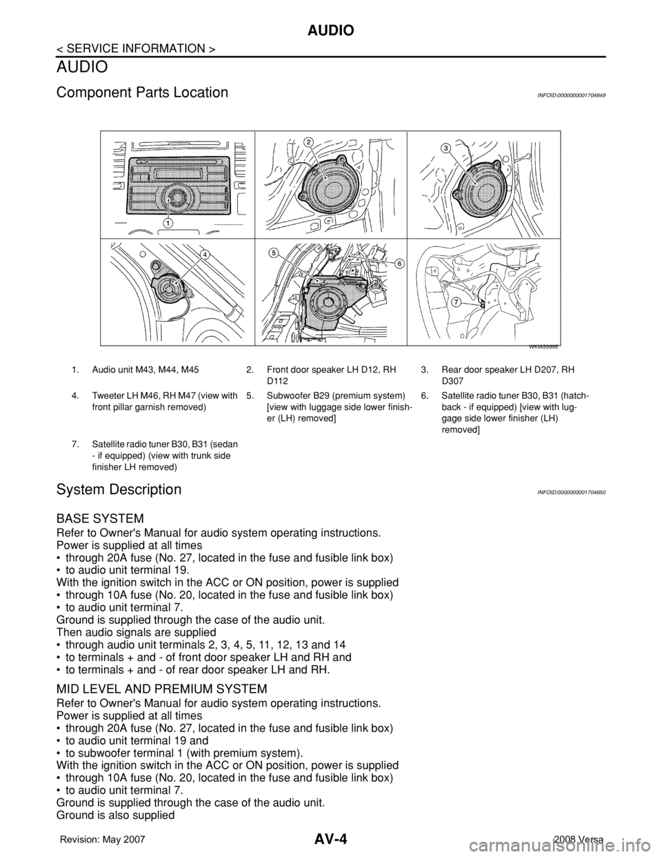
Component Parts LocationINFOID:0000000001704649
System DescriptionINFOID:0000000001704650
BASE SYSTEM
Refer to Owner's Manual for audio system operating instructions.
Power is supplied at all times
• through 20A fuse (No. 27, located in the fuse and fusible link box)
• to audio unit terminal 19.
With the ignition switch in the ACC or ON position, power is supplied
• through 10A fuse (No. 20, located in the fuse and fusible link box)
• to audio unit terminal 7.
Ground is supplied through the case of the audio unit.
Then audio signals are supplied
• through audio unit terminals 2, 3, 4, 5, 11, 12, 13 and 14
• to terminals + and - of front door speaker LH and RH and
• to terminals + and - of rear door speaker LH and RH.
MID LEVEL AND PREMIUM SYSTEM
Refer to Owner's Manual for audio system operating instructions.
Power is supplied at all times
• through 20A fuse (No. 27, located in the fuse and fusible link box)
• to audio unit terminal 19 and
• to subwoofer terminal 1 (with premium system).
With the ignition switch in the ACC or ON position, power is supplied
• through 10A fuse (No. 20, located in the fuse and fusible link box)
• to audio unit terminal 7.
Ground is supplied through the case of the audio unit.
Ground is also supplied
1. Audio unit M43, M44, M45 2. Front door speaker LH D12, RH
D1123. Rear door speaker LH D207, RH
D307
4. Tweeter LH M46, RH M47 (view with
front pillar garnish removed) 5. Subwoofer B29 (premium system)
[view with luggage side lower finish-
er (LH) removed]6. Satellite radio tuner B30, B31 (hatch-
back - if equipped) [view with lug-
gage side lower finisher (LH)
removed]
7. Satellite radio tuner B30, B31 (sedan
- if equipped) (view with trunk side
finisher LH removed)
WKIA5999E
Page 397 of 2771
AV-38
< SERVICE INFORMATION >
AUDIO
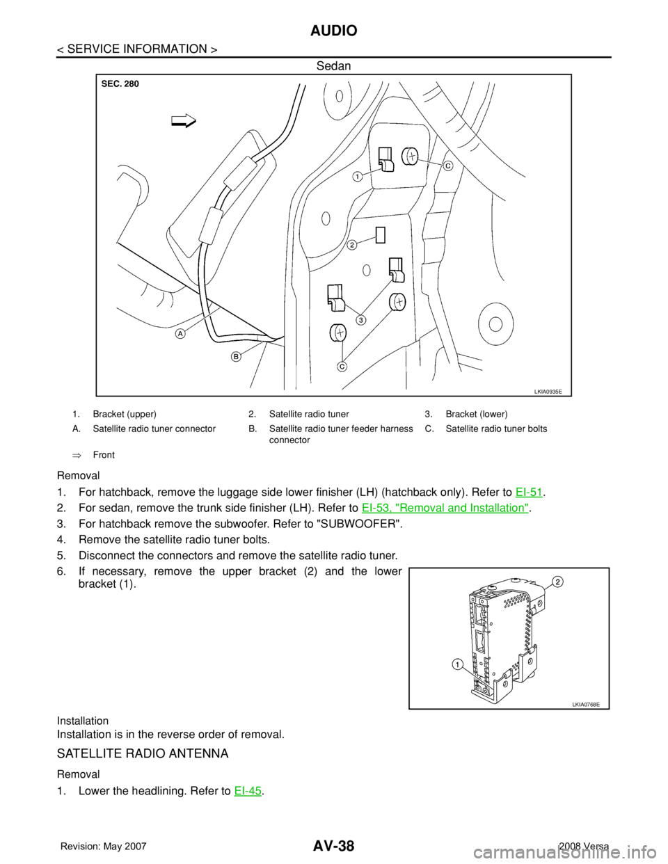
Sedan
Removal
1. For hatchback, remove the luggage side lower finisher (LH) (hatchback only). Refer to EI-51.
2. For sedan, remove the trunk side finisher (LH). Refer to EI-53, "
Removal and Installation".
3. For hatchback remove the subwoofer. Refer to "SUBWOOFER".
4. Remove the satellite radio tuner bolts.
5. Disconnect the connectors and remove the satellite radio tuner.
6. If necessary, remove the upper bracket (2) and the lower
bracket (1).
Installation
Installation is in the reverse order of removal.
SATELLITE RADIO ANTENNA
Removal
1. Lower the headlining. Refer to EI-45.
LKIA0935E
1. Bracket (upper) 2. Satellite radio tuner 3. Bracket (lower)
A. Satellite radio tuner connector B. Satellite radio tuner feeder harness
connectorC. Satellite radio tuner bolts
⇒Front
LKIA0768E
Page 402 of 2771

TELEPHONE
AV-43
< SERVICE INFORMATION >
C
D
E
F
G
H
I
J
L
MA
B
AV
N
O
P
TELEPHONE
Component Parts and Harness Connector LocationINFOID:0000000001704677
System DescriptionINFOID:0000000001704678
BLUETOOTH® HANDS-FREE PHONE SYSTEM
Refer to the Owner's Manual for Bluetooth telephone system operating instructions.
NOTE:
Cellular telephones must have their wireless connection set up (paired) before using the Bluetooth telephone
system.
Bluetooth telephone system allows users who have a Bluetooth cellular telephone to make a wireless connec-
tion between their cellular telephone and the Bluetooth control unit. Hands-free cellular telephone calls can be
sent and received. Personal memos can be created using the NISSAN Voice Recognition system. Some Blue-
WKIA6000E
1. Audio unit M43, M44, M45 2. Steering wheel audio control
switches3. Bluetooth microphone R15
4. Bluetooth ON indicator R15 5. Bluetooth antenna (hatchback) 6. Bluetooth control unit B121, B122 (hatch-
back) [view with luggage side lower finish-
er (RH) removed]
7. Bluetooth antenna (sedan) 8. Bluetooth control unit B121, B122
(sedan) (view with trunk side fin-
isher RH removed)
Page 415 of 2771
AV-56
< SERVICE INFORMATION >
TELEPHONE
Removal
1. For hatchback, remove luggage side lower finish (RH). Refer to EI-51, "Removal and Installation".
• Disconnect Bluetooth antenna harness clip.
2. For sedan, remove the trunk room side finisher (RH). Refer to EI-53, "
Removal and Installation".
• Disconnect the Bluetooth antenna harness connector.
3. Disconnect the Bluetooth control unit harness connector.
4. Remove the Bluetooth control unit upper and lower bracket bolts.
5. Unhook the Bluetooth control unit upper and lower brackets and remove Bluetooth control unit.
6. Remove Bluetooth control unit bracket screws and remove the upper and lower brackets from unit.
Installation
Installation is in the reverse order of removal.
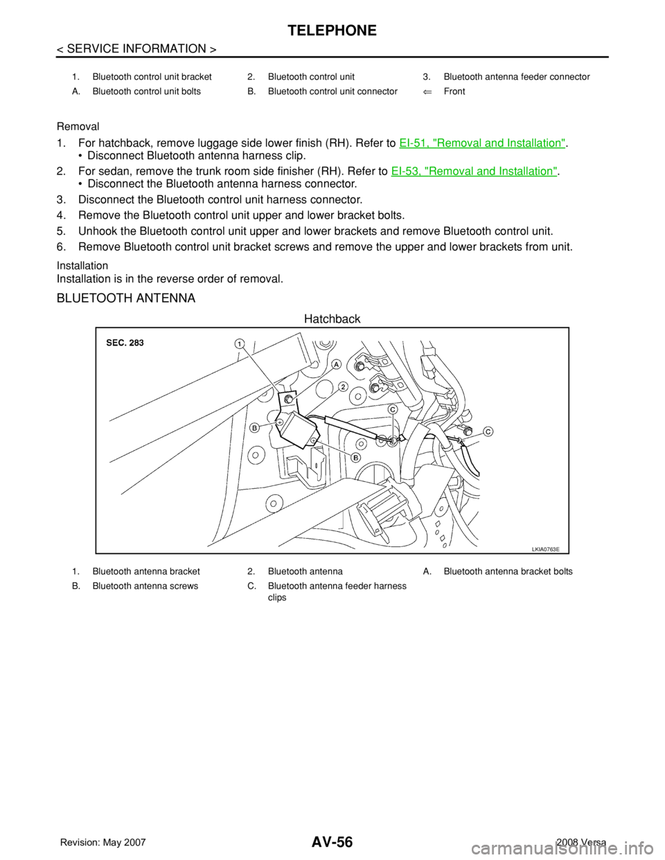
BLUETOOTH ANTENNA
Hatchback
1. Bluetooth control unit bracket 2. Bluetooth control unit 3. Bluetooth antenna feeder connector
A. Bluetooth control unit bolts B. Bluetooth control unit connector⇐Front
LKIA0763E
1. Bluetooth antenna bracket 2. Bluetooth antenna A. Bluetooth antenna bracket bolts
B. Bluetooth antenna screws C. Bluetooth antenna feeder harness
clips
Page 422 of 2771

BCS-6
< SERVICE INFORMATION >
BCM (BODY CONTROL MODULE)
• When CAN communication operation is detected, it switches to CAN communication status.
• When a state of the following switches changes, it switches to CAN communication state:
- Ignition switch
- Key switch (without Intelligent Key)
- Key switch and ignition knob switch (with Intelligent Key)
- Hazard switch
- Door lock/unlock switch
- Front door switch (LH, RH)
- Rear door switch (LH, RH)
- Back door lock assembly (Hatchback)
- Trunk key cylinder switch (Sedan)
- Trunk lamp switch and trunk release solenoid (Sedan)
- Combination switch (passing, lighting switch 1st position, front fog lamp)
- Keyfob (lock/unlock signal)
- Front door key cylinder switch LH
• When control performed only by BCM is required by switch, it shifts to CAN communication inactive
mode.
• Status of combination switch reading function is changed.
SYSTEMS CONTROLLED BY BCM DIRECTLY
• Power door lock system. Refer to BL-22 .
• Remote keyless entry system. Refer to BL-51
.
• Power window system. Refer to GW-18
. NOTE
• Sunroof system. Refer to RF-10. NOTE
• Room lamp timer. Refer to LT- 8 9 .
• Rear wiper and washer system. Refer to WW-24
.
NOTE:
Power supply only. No system control.
SYSTEMS CONTROLLED BY BCM AND IPDM E/R
• Panic system. Refer to BL-51 .
• Vehicle security (theft warning) system. Refer to BL-187
.
• NVIS(NATS) system. Refer to BL-210
.
• Headlamp, tail lamp and battery saver control systems. Refer to LT- 7 2
, LT- 4 or LT- 2 5 .
• Front fog lamp. Refer to LT- 3 9
.
• Front wiper and washer system. Refer to WW-3
.
• Rear window defogger system. Refer to GW-49
.
SYSTEMS CONTROLLED BY BCM AND COMBINATION METER
• Warning chime. Refer to DI-41 .
• Turn signal and hazard warning lamps. Refer to LT- 4 8
.
SYSTEMS CONTROLLED BY BCM AND INTELLIGENT KEY UNIT
• Intelligent Key system. Refer to BL-74 .
MAJOR COMPONENTS AND CONTROL SYSTEM
System Input Output
Remote keyless entry systemRemote keyless entry receiver
(keyfob)• All door locking actuators
• Turn signal lamp (LH, RH)
• Combination meter (turn signal lamp)
Intelligent Key system Intelligent Key unit• All door locking actuators
• Turn signal lamp (LH, RH)
• Combination meter (turn signal lamp)
Power door lock systemFront power door lock/unlock
switch (LH, RH)All door locking actuators
Power supply (IGN/RAP) to power
windowIgnition retained power supply Power supply to power window and sunroof system
Power supply (BAT) to power window Battery power supply Power supply to power window and sunroof system
Page 423 of 2771

BCM (BODY CONTROL MODULE)
BCS-7
< SERVICE INFORMATION >
C
D
E
F
G
H
I
J
L
MA
B
BCS
N
O
P
CAN Communication System DescriptionINFOID:0000000001704585
Refer to LAN-6, "System Description".
Panic alarm• Key switch
•KeyfobIPDM E/R
Vehicle security system• All door switches
•Keyfob
• Door lock/unlock switch
• Trunk key cylinder switch (Se-
dan)
• Front door key cylinder switch
LH• IPDM/ER
• Security indicator lamp
Battery saver control• Ignition switch
• Combination switchIPDM E/R
Headlamp Combination switch IPDM E/R
Tail lamp Combination switch IPDM E/R
Front fog lamp Combination switch IPDM E/R
Turn signal lamp Combination switch• Turn signal lamp
• Combination meter
Hazard lamp Hazard switch• Turn signal lamp
• Combination meter
Room lamp timer• Key switch
•Keyfob
• Main power window and door
lock/unlock switch
• Front door switch LH
• All door switchInterior room lamp
Back door switch signal (Hatchback) Back door lock assembly Luggage room lamp
Back door lock signal (Hatchback) Back door lock assembly Back door opener
Trunk lamp switch signalTrunk lamp switch and trunk re-
lease solenoidLuggage room lamp
Trunk lid opener signalTrunk lamp switch and trunk re-
lease solenoidTrunk lid opener
Key warning chime• Key switch
• Front door switch LHCombination meter (warning buzzer)
Light warning chime• Combination switch
• Key switch
• Front door switch LHCombination meter (warning buzzer)
Seat belt warning chime• Seat belt buckle switch LH
• Ignition switchCombination meter (warning buzzer)
Front wiper and washer system• Combination switch
• Ignition switchIPDM E/R
Rear window defogger Rear window defogger switch IPDM E/R
Rear wiper and washer system• Combination switch
• Ignition switchRear wiper motor
A/C switch signal Front air control ECM
Blower fan switch signal Front air control ECM
A/C indicator signal Front air control A/C indicator
Low tire pressure warning system Remote keyless entry receiver Combination meterSystem Input Output
Page 429 of 2771
BCM (BODY CONTROL MODULE)
BCS-13
< SERVICE INFORMATION >
C
D
E
F
G
H
I
J
L
MA
B
BCS
N
O
P
30*1VBack door/trunk out-
putOutput —Back door open (switch
closed)0V
Back door closed (switch
open)5V
30
*2VBack door opener
switchInput —All doors locked (SW OFF) Battery voltage
All doors unlocked (SW ON) 0V
30
*3VTrunk lid opener
switchInput —All doors locked (SW OFF) Battery voltage
All doors unlocked (SW ON) 0V
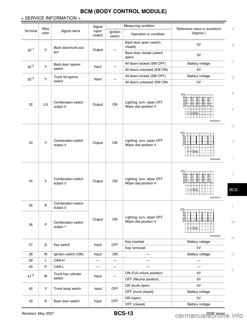
32 LGCombination switch
output 5Output ONLighting, turn, wiper OFF
Wiper dial position 4
33 YCombination switch
output 4Output ONLighting, turn, wiper OFF
Wiper dial position 4
34 VCombination switch
output 3Output ONLighting, turn, wiper OFF
Wiper dial position 4
35 RCombination switch
output 2
Output ONLighting, turn, wiper OFF
Wiper dial position 4
36 PCombination switch
output 1
37 G Key switch Input OFFKey inserted Battery voltage
Key removed 0V
38 W Ignition switch (ON) Input ON — Battery voltage
39 L CAN-H — — — —
40 P CAN-L — — — —
41
*5WTrunk key cylinder
switchInput —ON (Full unlock position) 0V
OFF (Neutral position) 5V
42 Y Trunk lamp switch Input OFFON (trunk open) 0V
OFF (trunk closed) Battery voltage
43 R Back door switch Input OFFON (open) 0V
OFF (closed) Battery voltage Te r m i n a lWire
colorSignal nameSignal
input/
outputMeasuring condition
Reference value or waveform
(Approx.) Ignition
switchOperation or condition
SKIA5291E
SKIA5292E
SKIA5291E
SKIA5292E
Page 430 of 2771
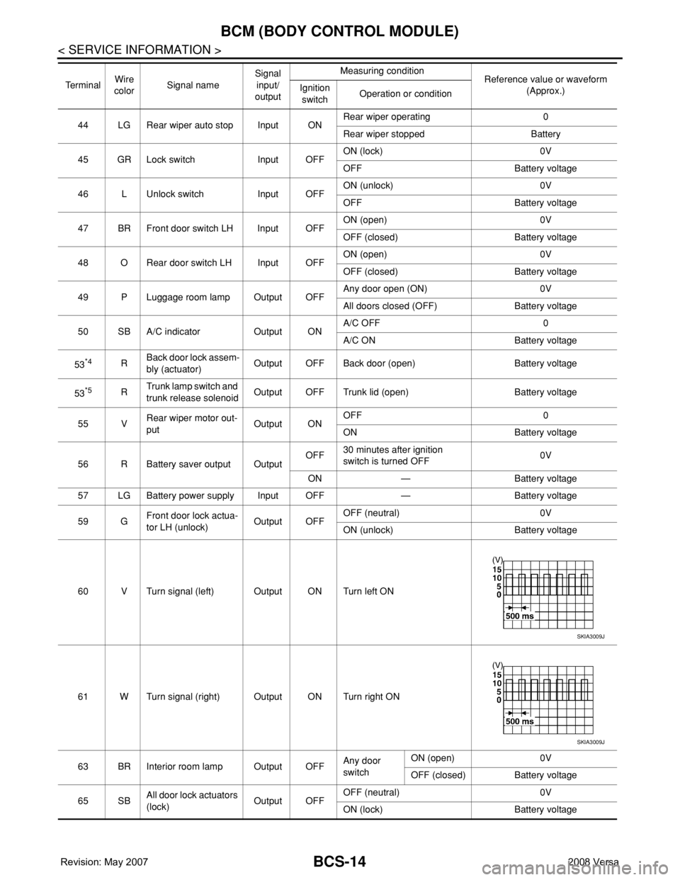
BCS-14
< SERVICE INFORMATION >
BCM (BODY CONTROL MODULE)
44 LG Rear wiper auto stop Input ONRear wiper operating 0
Rear wiper stopped Battery
45 GR Lock switch Input OFFON (lock) 0V
OFF Battery voltage
46 L Unlock switch Input OFFON (unlock) 0V
OFF Battery voltage
47 BR Front door switch LH Input OFFON (open) 0V
OFF (closed) Battery voltage
48 O Rear door switch LH Input OFFON (open) 0V
OFF (closed) Battery voltage
49 P Luggage room lamp Output OFFAny door open (ON) 0V
All doors closed (OFF) Battery voltage
50 SB A/C indicator Output ONA/C OFF 0
A/C ON Battery voltage
53
*4RBack door lock assem-
bly (actuator)Output OFF Back door (open) Battery voltage
53
*5RTrunk lamp switch and
trunk release solenoidOutput OFF Trunk lid (open) Battery voltage
55 VRear wiper motor out-
putOutput ONOFF 0
ON Battery voltage
56 R Battery saver output OutputOFF30 minutes after ignition
switch is turned OFF0V
ON — Battery voltage
57 LG Battery power supply Input OFF — Battery voltage
59 GFront door lock actua-
tor LH (unlock)Output OFFOFF (neutral) 0V
ON (unlock) Battery voltage
60 V Turn signal (left) Output ON Turn left ON
61 W Turn signal (right) Output ON Turn right ON
63 BR Interior room lamp Output OFFAny door
switchON (open) 0V
OFF (closed) Battery voltage
65 SBAll door lock actuators
(lock)Output OFFOFF (neutral) 0V
ON (lock) Battery voltage Te r m i n a lWire
colorSignal nameSignal
input/
outputMeasuring condition
Reference value or waveform
(Approx.) Ignition
switchOperation or condition
SKIA3009J
SKIA3009J