2008 NISSAN LATIO change time
[x] Cancel search: change timePage 2450 of 2771

IPDM E/R (INTELLIGENT POWER DISTRIBUTION MODULE ENGINE ROOM)
PG-17
< SERVICE INFORMATION >
C
D
E
F
G
H
I
J
L
MA
B
PG
N
O
P
IPDM E/R STATUS CONTROL
In order to save power, IPDM E/R switches status by itself based on each operating condition.
1. CAN communication status
• CAN communication is normally performed with other control units.
• Individual unit control by IPDM E/R is normally performed.
• When sleep request signal is received from BCM, mode is switched to sleep waiting status.
2. Sleep waiting status
• Process to stop CAN communication is activated.
• All systems controlled by IPDM E/R are stopped. When 1 second has elapsed after CAN communica-
tion with other control units is stopped, mode switches to sleep status.
3. Sleep status
• IPDM E/R operates in low current-consumption mode.
• CAN communication is stopped.
• When a change in CAN communication signal is detected, mode switches to CAN communication sta-
tus.
• When a change in ignition switch signal is detected, mode switches to CAN communication status.
CAN Communication System DescriptionINFOID:0000000001704698
Refer to LAN-6, "System Description".
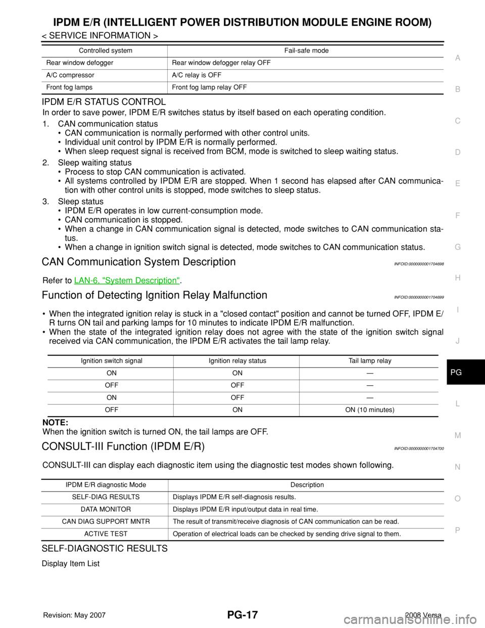
Function of Detecting Ignition Relay MalfunctionINFOID:0000000001704699
• When the integrated ignition relay is stuck in a "closed contact" position and cannot be turned OFF, IPDM E/
R turns ON tail and parking lamps for 10 minutes to indicate IPDM E/R malfunction.
• When the state of the integrated ignition relay does not agree with the state of the ignition switch signal
received via CAN communication, the IPDM E/R activates the tail lamp relay.
NOTE:
When the ignition switch is turned ON, the tail lamps are OFF.
CONSULT-III Function (IPDM E/R)INFOID:0000000001704700
CONSULT-III can display each diagnostic item using the diagnostic test modes shown following.
SELF-DIAGNOSTIC RESULTS
Display Item List
Rear window defogger Rear window defogger relay OFF
A/C compressor A/C relay is OFF
Front fog lamps Front fog lamp relay OFFControlled system Fail-safe mode
Ignition switch signal Ignition relay status Tail lamp relay
ON ON —
OFF OFF —
ON OFF —
OFF ON ON (10 minutes)
IPDM E/R diagnostic Mode Description
SELF-DIAG RESULTS Displays IPDM E/R self-diagnosis results.
DATA MONITOR Displays IPDM E/R input/output data in real time.
CAN DIAG SUPPORT MNTR The result of transmit/receive diagnosis of CAN communication can be read.
ACTIVE TEST Operation of electrical loads can be checked by sending drive signal to them.
Page 2537 of 2771

SQUEAK AND RATTLE TROUBLE DIAGNOSES
RF-7
< SYMPTOM DIAGNOSIS >
C
D
E
F
G
H
J
K
L
MA
B
RF
N
O
P
2. Trunk lid striker out of adjustment
3. The trunk lid torsion bars knocking together
4. A loose license plate or bracket
Most of these incidents can be repaired by adjusting, securing or insulating the item(s) or component(s) caus-
ing the noise.
SUNROOF/HEADLINING
Noises in the sunroof/headlining area can often be traced to one of the following:
1. Sunroof lid, rail, linkage or seals making a rattle or light knocking noise
2. Sun visor shaft shaking in the holder
3. Front or rear windshield touching headliner and squeaking
Again, pressing on the components to stop the noise while duplicating the conditions can isolate most of these
incidents. Repairs usually consist of insulating with felt cloth tape.
OVERHEAD CONSOLE (FRONT AND REAR)
Overhead console noises are often caused by the console panel clips not being engaged correctly. Most of
these incidents are repaired by pushing up on the console at the clip locations until the clips engage.
In addition look for:
1. Loose harness or harness connectors.
2. Front console map/reading lamp lens loose.
3. Loose screws at console attachment points.
SEATS
When isolating seat noise it's important to note the position the seat is in and the load placed on the seat when
the noise is present. These conditions should be duplicated when verifying and isolating the cause of the
noise.
Cause of seat noise include:
1. Headrest rods and holder
2. A squeak between the seat pad cushion and frame
3. The rear seatback lock and bracket
These noises can be isolated by moving or pressing on the suspected components while duplicating the con-
ditions under which the noise occurs. Most of these incidents can be repaired by repositioning the component
or applying urethane tape to the contact area.
UNDERHOOD
Some interior noise may be caused by components under the hood or on the engine wall. The noise is then
transmitted into the passenger compartment.
Causes of transmitted underhood noise include:
1. Any component installed on the engine wall
2. Components that pass through the engine wall
3. Engine wall mounts and connectors
4. Loose radiator pins
5. Hood bumpers out of adjustment
6. Hood striker out of adjustment
These noises can be difficult to isolate since they cannot be reached from the interior of the vehicle. The best
method is to secure, move or insulate one component at a time and test drive the vehicle. Also, engine RPM
or load can be changed to isolate the noise. Repairs can usually be made by moving, adjusting, securing, or
insulating the component causing the noise.
Page 2541 of 2771

TROUBLE DIAGNOSIS
RF-11
< FUNCTION DIAGNOSIS >
C
D
E
F
G
H
J
K
L
MA
B
RF
N
O
P
• to sunroof motor assembly terminal 1
• through sunroof switch terminal 3
• through sunroof switch terminal 2
• through grounds M57 and M61.
Then the sunroof will tilt up/slide closed.
TILT DOWN/SLIDE OPEN OPERATION
When down/open switch is pressed, ground is supplied
• to sunroof motor assembly terminal 5
• through sunroof switch terminal 1
• through sunroof switch terminal 2
• through grounds M57 and M61.
Then the sunroof will tilt down/slide open.
AUTO OPERATION
The power sunroof AUTO feature makes it possible to slide open and slide closed or tilt up and tilt down the
sunroof without holding the sunroof switch in the UP/CLOSE or DOWN/OPEN position.
RETAINED POWER OPERATION
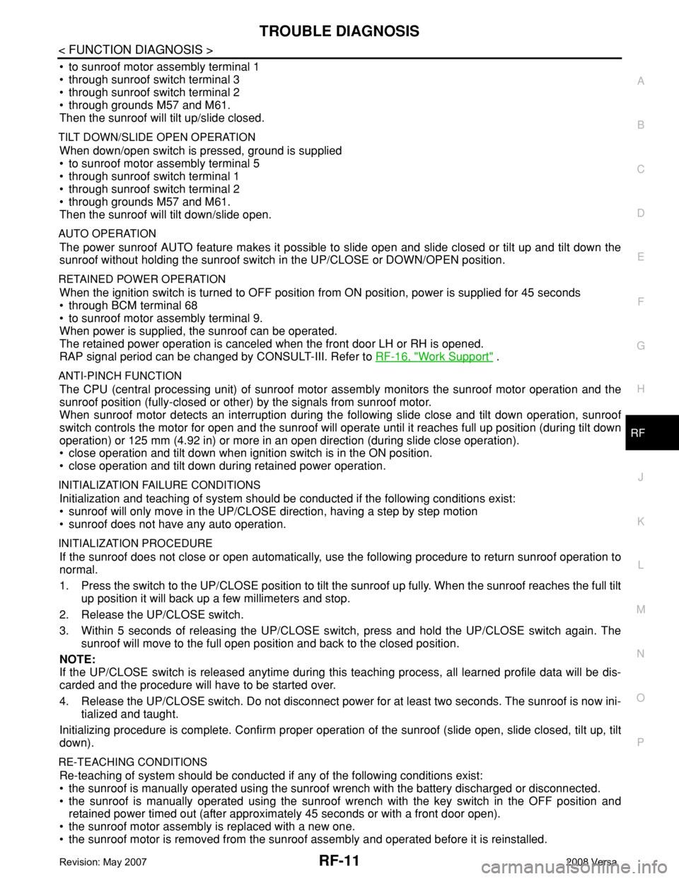
When the ignition switch is turned to OFF position from ON position, power is supplied for 45 seconds
• through BCM terminal 68
• to sunroof motor assembly terminal 9.
When power is supplied, the sunroof can be operated.
The retained power operation is canceled when the front door LH or RH is opened.
RAP signal period can be changed by CONSULT-III. Refer to RF-16, "
Work Support" .
ANTI-PINCH FUNCTION
The CPU (central processing unit) of sunroof motor assembly monitors the sunroof motor operation and the
sunroof position (fully-closed or other) by the signals from sunroof motor.
When sunroof motor detects an interruption during the following slide close and tilt down operation, sunroof
switch controls the motor for open and the sunroof will operate until it reaches full up position (during tilt down
operation) or 125 mm (4.92 in) or more in an open direction (during slide close operation).
• close operation and tilt down when ignition switch is in the ON position.
• close operation and tilt down during retained power operation.
INITIALIZATION FAILURE CONDITIONS
Initialization and teaching of system should be conducted if the following conditions exist:
• sunroof will only move in the UP/CLOSE direction, having a step by step motion
• sunroof does not have any auto operation.
INITIALIZATION PROCEDURE
If the sunroof does not close or open automatically, use the following procedure to return sunroof operation to
normal.
1. Press the switch to the UP/CLOSE position to tilt the sunroof up fully. When the sunroof reaches the full tilt
up position it will back up a few millimeters and stop.
2. Release the UP/CLOSE switch.
3. Within 5 seconds of releasing the UP/CLOSE switch, press and hold the UP/CLOSE switch again. The
sunroof will move to the full open position and back to the closed position.
NOTE:
If the UP/CLOSE switch is released anytime during this teaching process, all learned profile data will be dis-
carded and the procedure will have to be started over.
4. Release the UP/CLOSE switch. Do not disconnect power for at least two seconds. The sunroof is now ini-
tialized and taught.
Initializing procedure is complete. Confirm proper operation of the sunroof (slide open, slide closed, tilt up, tilt
down).
RE-TEACHING CONDITIONS
Re-teaching of system should be conducted if any of the following conditions exist:
• the sunroof is manually operated using the sunroof wrench with the battery discharged or disconnected.
• the sunroof is manually operated using the sunroof wrench with the key switch in the OFF position and
retained power timed out (after approximately 45 seconds or with a front door open).
• the sunroof motor assembly is replaced with a new one.
• the sunroof motor is removed from the sunroof assembly and operated before it is reinstalled.
Page 2542 of 2771

RF-12
< FUNCTION DIAGNOSIS >
TROUBLE DIAGNOSIS
• the sunroof motor is removed from the sunroof assembly and the glass panel position is changed.
RE-TEACHING PROCEDURE
1. Using the UP/CLOSE switch, move the sunroof toward the tilt position until it stops.
2. Release the UP/CLOSE switch.
3. Press the UP/CLOSE switch again and continuously hold. The sunroof will begin to move in about 10 sec-
onds.
4. Continue to hold the UP/CLOSE switch while the sunroof moves in a jogging motion to the full tilt position.
When the sunroof reaches the full tilt position, it will back up a few millimeters and stop.
5. Release the UP/CLOSE switch.
6. Within 5 seconds of releasing the UP/CLOSE switch, press and hold the UP/CLOSE switch again. The
sunroof will move to the full open position and back to the closed position.
NOTE:
If the UP/CLOSE switch is released anytime during this teaching process, all learned profile data will be dis-
carded and the procedure will have to be started over.
7. Release the UP/CLOSE switch. Do not disconnect power for at least two seconds. The sunroof is now re-
taught.
CAN Communication System DescriptionINFOID:0000000001704193
Refer to LAN-6 .
Page 2615 of 2771

SQUEAK AND RATTLE TROUBLE DIAGNOSES
SE-7
< SERVICE INFORMATION >
C
D
E
F
G
H
J
K
L
MA
B
SE
N
O
P
Most of these incidents can be repaired by adjusting, securing or insulating the item(s) or component(s) caus-
ing the noise.
SUNROOF/HEADLINING
Noises in the sunroof/headlining area can often be traced to one of the following:
1. Sunroof lid, rail, linkage or seals making a rattle or light knocking noise
2. Sun visor shaft shaking in the holder
3. Front or rear windshield touching headliner and squeaking
Again, pressing on the components to stop the noise while duplicating the conditions can isolate most of these
incidents. Repairs usually consist of insulating with felt cloth tape.
OVERHEAD CONSOLE (FRONT AND REAR)
Overhead console noises are often caused by the console panel clips not being engaged correctly. Most of
these incidents are repaired by pushing up on the console at the clip locations until the clips engage.
In addition look for:
1. Loose harness or harness connectors.
2. Front console map/reading lamp lense loose.
3. Loose screws at console attachment points.
SEATS
When isolating seat noise it's important to note the position the seat is in and the load placed on the seat when
the noise is present. These conditions should be duplicated when verifying and isolating the cause of the
noise.
Cause of seat noise include:
1. Headrest rods and holder
2. A squeak between the seat pad cushion and frame
3. The rear seatback lock and bracket
These noises can be isolated by moving or pressing on the suspected components while duplicating the con-
ditions under which the noise occurs. Most of these incidents can be repaired by repositioning the component
or applying urethane tape to the contact area.
UNDERHOOD
Some interior noise may be caused by components under the hood or on the engine wall. The noise is then
transmitted into the passenger compartment.
Causes of transmitted underhood noise include:
1. Any component mounted to the engine wall
2. Components that pass through the engine wall
3. Engine wall mounts and connectors
4. Loose radiator mounting pins
5. Hood bumpers out of adjustment
6. Hood striker out of adjustment
These noises can be difficult to isolate since they cannot be reached from the interior of the vehicle. The best
method is to secure, move or insulate one component at a time and test drive the vehicle. Also, engine RPM
or load can be changed to isolate the noise. Repairs can usually be made by moving, adjusting, securing, or
insulating the component causing the noise.
Page 2651 of 2771

TROUBLE DIAGNOSIS
SRS-17
< SYMPTOM DIAGNOSIS >
C
D
E
F
G
I
J
K
L
MA
B
SRS
N
O
P
HOW TO CHANGE BETWEEN SELF-DIAGNOSIS MODE AND USER MODE WITH CONSULT-III
From User Mode to Diagnosis Mode
After selecting “AIR BAG” on the “SELECT SYSTEM” screen, User mode automatically changes to Diagnosis
mode.
From Diagnosis Mode to User Mode
To return to User mode from Diagnosis mode, touch “BACK” key of CONSULT-III until “SELECT SYSTEM”
appears, Diagnosis mode automatically changes to User mode.
HOW TO ERASE SELF-DIAGNOSIS RESULTS
NOTE:
If the memory in “SELF-DIAG [PAST]” is not erased, User mode will continue to show the system mal-
function by the operation of the warning lamp even if the malfunction is repaired completely.
• “SELF-DIAG [CURRENT]”
A current self-diagnosis result is displayed on the CONSULT-III screen in real time. After the malfunction is
repaired completely, no malfunction is detected on “SELF-DIAG [CURRENT]”.
• “SELF-DIAG [PAST]”
Return to the “SELF-DIAG [CURRENT]” CONSULT-III screen by touching “BACK” key of CONSULT-III and
select “SELF-DIAG [CURRENT]” in SELECT DIAG MODE. Touch “ERASE” in “SELF-DIAG [CURRENT]”
mode.
• “TROUBLE DIAG RECORD”
The memory of “TROUBLE DIAG RECORD” cannot be erased.
Self-Diagnosis Function (Without CONSULT-III)INFOID:0000000001703920
The reading of these results is accomplished using one of two modes —“User mode” and “Diagnosis mode”.
HOW TO CHANGE BETWEEN USER MODE AND SELF-DIAGNOSIS MODE WITHOUT CONSULT-
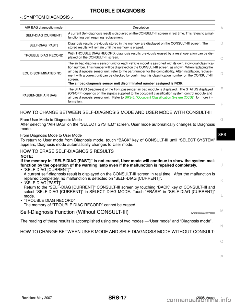
AIR BAG diagnostic mode Description
SELF-DIAG [CURRENT]A current Self-diagnosis result is displayed on the CONSULT-III screen in real time. This refers to a mal-
functioning part requiring replacement.
SELF-DIAG [PAST]Diagnosis results previously stored in the memory are displayed on the CONSULT-III screen. The
stored results will remain until the memory is erased.
TROUBLE DIAG RECORDWith TROUBLE DIAG RECORD, diagnosis results previously erased by a reset operation can be dis-
played on the CONSULT-III screen.
ECU DISCRIMINATED NO.The air bag diagnosis sensor unit for each vehicle model is assigned with its own, individual classifica-
tion number. This number will be displayed on the CONSULT-III screen, as shown. When replacing the
air bag diagnosis sensor unit, refer to the part number for the compatibility. After installation, replace-
ment with a correct unit can be checked by confirming this classification number on the CONSULT-III
screen.
The air bag diagnosis sensor unit discriminated number assigned is F636.
PASSENGER AIR BAGThe STATUS (readiness) of the front passenger air bag module is displayed. The STATUS displayed
(ON/OFF) depends on the signals supplied to the occupant classification system control module and
air bag diagnosis sensor unit. Refer to SRS-5, "
Occupant Classification System (OCS)" for more in-
formation.
Page 2693 of 2771
![NISSAN LATIO 2008 Service Repair Manual STC-10
< SERVICE INFORMATION >[EPS]
TROUBLE DIAGNOSIS
*1 : In the front of the value, “L” is displayed at steering left and “R” is displayed at steering right.
*2 : Almost in accordance with t NISSAN LATIO 2008 Service Repair Manual STC-10
< SERVICE INFORMATION >[EPS]
TROUBLE DIAGNOSIS
*1 : In the front of the value, “L” is displayed at steering left and “R” is displayed at steering right.
*2 : Almost in accordance with t](/manual-img/5/57360/w960_57360-2692.png)
STC-10
< SERVICE INFORMATION >[EPS]
TROUBLE DIAGNOSIS
*1 : In the front of the value, “L” is displayed at steering left and “R” is displayed at steering right.
*2 : Almost in accordance with the value of “MOTOR SIG”. It is not a malfunction though these values are not accorded when steering
quickly.
*3 : It is not a malfunction, though it might not be corresponding just after ignition switch is turned ON.
*4 : It turns to OFF after waiting for a short period of time.
EPS Terminal and Reference ValueINFOID:0000000001703880
EPS HARNESS CONNECTOR TERMINAL LAYOUT
TERMINALS AND REFERENCE VALUES FOR EPS CONTROL UNIT
Monitor item (Unit) Content Condition Display value
MOTOR VOL (V)Power supply voltage for
EPS control unitIgnition switch: ON Battery voltage
TORQUE SENSOR (Nm)Steering wheel turning
forceEngine runningSteering wheel: Not
steering (There is no
steering force) 0.00 Nm
Steering wheel: Steer-
ing0 – 8.19 Nm
*1 (The value
is changed according to
steering left or right)
MOTOR SIG (A)Command current to EPS
motorEngine runningSteering wheel: Not
steering (There is no
steering force)0.00 A
Steering wheel: Steer-
ing0 – 65.00 A (The value is
changed according to
steering left or right)
MOTOR CURRENT (A)Consumption current of
EPS motorEngine runningSteering wheel: Not
steering (There is no
steering force)0.00 A
Steering wheel: Steer-
ing0 – 65.00 A
*2 (The value
is changed according to
steering left or right)
VEHICLE SPEED (km/h) or (mph) Vehicle speedVehicle stopped 0 km/h (0 mph)
While drivingApproximately equal to
the indication on speed-
ometer (Inside of ±10%)
*3
WARNING LAMP (ON/OFF)EPS warning lamp condi-
tionEPS warning lamp: ON ON
EPS warning lamp: OFF OFF
DERATING STAT (ON/OFF) Protect overload status Engine runningSteering wheel: Nor-
mal steeringOFF
Steering wheel: Steer-
ing over the stopON
*4
ENGINE STATUS (RUN/STOP) Engine statusEngine stopped
(Engine speed: Less than 400 rpm)STOP
Engine running
(Engine speed: 400 rpm or more)RUN
SGIA1624E
Page 2743 of 2771

WW-10
< SERVICE INFORMATION >
FRONT WIPER AND WASHER SYSTEM
How to Proceed with Trouble Diagnosis
INFOID:0000000001704542
1. Confirm symptoms and customer complaint.
2. Understand operation description and function description. Refer to WW-3, "
System Description" .
3. Perform preliminary check. Refer to WW-10, "
Preliminary Check" .
4. Check symptom and repair or replace malfunctioning parts.
5. Does front wiper and washer operate normally? If YES, GO TO 6. If NO, GO TO 4.
6. Inspection End.
Preliminary CheckINFOID:0000000001704543
CHECK POWER SUPPLY AND GROUND CIRCUIT FOR BCM
Refer to BCS-15, "BCM Power Supply and Ground Circuit Inspection"
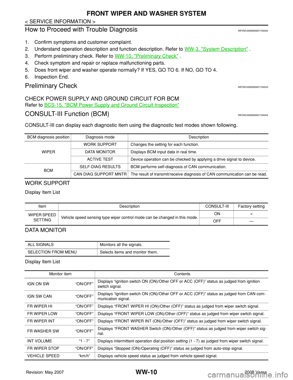
CONSULT-III Function (BCM)INFOID:0000000001704544
CONSULT-III can display each diagnostic item using the diagnostic test modes shown following.
WORK SUPPORT
Display Item List
DATA MONITOR
Display Item List
BCM diagnosis position Diagnosis mode Description
WIPERWORK SUPPORT Changes the setting for each function.
DATA MONITOR Displays BCM input data in real time.
ACTIVE TEST Device operation can be checked by applying a drive signal to device.
BCMSELF-DIAG RESULTS BCM performs self-diagnosis of CAN communication.
CAN DIAG SUPPORT MNTR The result of transmit/receive diagnosis of CAN communication can be read.
Item Description CONSULT-III Factory setting
WIPER SPEED
SETTINGVehicle speed sensing type wiper control mode can be changed in this mode.ON×
OFF —
ALL SIGNALS Monitors all the signals.
SELECTION FROM MENU Selects items and monitor them.
Monitor item Contents
IGN ON SW “ON/OFF”Displays “ignition switch ON (ON)/Other OFF or ACC (OFF)” status as judged from ignition
switch signal.
IGN SW CAN “ON/OFF”Displays “ignition switch ON (ON)/Other OFF or ACC (OFF)” status as judged from CAN com-
munication signal.
FR WIPER HI “ON/OFF” Displays “FRONT WIPER HI (ON)/Other (OFF)” status as judged from wiper switch signal.
FR WIPER LOW “ON/OFF” Displays “FRONT WIPER LOW (ON)/Other (OFF)” status as judged from wiper switch signal.
FR WIPER INT “ON/OFF” Displays “FRONT WIPER INT (ON)/Other (OFF)” status as judged from wiper switch signal.
FR WASHER SW “ON/OFF”Displays “FRONT WASHER Switch (ON)/Other (OFF)” status as judged from wiper switch sig-
nal.
INT VOLUME “1 - 7” Displays intermittent operation dial position setting (1 - 7) as judged from wiper switch signal.
FR WIPER STOP “ON/OFF” Displays “Stopped (ON)/Operating (OFF)” status as judged from auto-stop signal.
VEHICLE SPEED “km/h” Displays vehicle speed status as judged from vehicle speed signal.