2008 NISSAN LATIO differential
[x] Cancel search: differentialPage 4 of 2771

2008
QUICK REFERENCE CHART: VERSA
QUICK REFERENCE CHART: VERSA
Engine Tune-up DataINFOID:0000000001903528
GENERAL SPECIFICATIONS
SPARK PLUG
Unit: mm (in)
Front Wheel Alignment (Unladen*)INFOID:0000000001903529
Engine typeMR18DE
Cylinder arrangement In-line 4
Displacement cm
3 (cu in)1,797 (109.65)
Bore and stroke mm (in) 84.0 x 81.1 (3.307 x 3.192)
Valve arrangement DOHC
Firing order 1-3-4-2
Number of piston rings Compression 2
Oil 1
Compression ratio 9.9
Compression pressure
kPa (bar, kg/cm
2 , psi) / 250 rpm Standard 1,500 (15.0, 15.3, 217.6)
Minimum 1,200 (12.0, 12.2, 174)
Differential limit between cylinders 100 (1.0, 1.0, 15)
Plug type
Iridium-tipped TYPE
Make DENSO
Standard type FXE20HR11
Spark plug gap Nominal: 1.1 (0.043)
Camber
Degree minute (Decimal degree)RH
Minimum - 1
° 05 ′ (- 1.08 °)
Nominal - 0 ° 20 ′ (- 0.33 °)
Maximum 0 ° 25 ′ (0.42 °)
LH Minimum - 0
° 55 ′ (- 0.92 °)
Nominal - 0 ° 10 ′ (- 0.17 °)
Maximum 0 ° 35 ′ (0.58 °)
Left and right difference
(RH - LH) Minimum -0
° 45 ′ (-0.75 °) or less
Nominal -0 ° 12 ′ (-0.20 °) or less
Maximum 0 ° 21 ′ (0.35 °) or less
Caster
Degree minute (Decimal degree) RH
Minimum 4
° 05 ′ (4.08 °)
Nominal 4 ° 50 ′ (4.83 °)
Maximum 5 ° 35 ′ (5.58 °)
LH Minimum 3
° 55 ′ (3.92 °)
Nominal 4 ° 40 ′ (4.67 °)
Maximum 5 ° 25 ′ (5.42 °)
Left and right difference
(RH - LH) Minimum -0
° 21 ′ (-0.35 °) or less
Nominal 0 ° 12 ′ (0.20 °) or less
Maximum 0 ° 45 ′ (0.75 °) or less
Page 16 of 2771

AT-4
Diagnosis Procedure .............................................210
KEY INTERLOCK CABLE ...............................213
Removal and Installation .......................................213
ON-VEHICLE SERVICE ..................................216
Control Valve Assembly and Accumulators ...........216
Park/Neutral Position (PNP) Switch ......................219
Revolution Sensor .................................................221
Turbine Revolution Sensor (Power Train Revolu-
tion Sensor) ...........................................................
222
Differential Side Oil Seal ........................................223
AIR BREATHER HOSE ...................................225
Removal and Installation .......................................225
TRANSAXLE ASSEMBLY ..............................226
Removal and Installation .......................................226
OVERHAUL .....................................................230
Component ............................................................230
Oil Channel ............................................................237
Location of Adjusting Shims, Needle Bearings and
Thrust Washers .....................................................
238
Location of Snap Rings .........................................239
DISASSEMBLY ...............................................240
Disassembly ..........................................................240
REPAIR FOR COMPONENT PARTS ..............257
Manual Shaft .........................................................257
Oil Pump ................................................................260
Control Valve Assembly ........................................263
Control Valve Upper Body .....................................272
Control Valve Lower Body .....................................276
Reverse Clutch ......................................................279
High Clutch ............................................................284
Forward and Overrun Clutches .............................288
Low & Reverse Brake ............................................295
Rear Internal Gear and Forward Clutch Hub .........299
Output Shaft, Output Gear, Idler Gear, Reduction
Pinion Gear and Bearing Retainer .........................
302
Band Servo Piston Assembly ................................307
Final Drive .............................................................313
ASSEMBLY ......................................................318
Assembly (1) .........................................................318
Adjustment (1) .......................................................319
Assembly (2) .........................................................325
Adjustment (2) .......................................................330
Assembly (3) .........................................................333
SERVICE DATA AND SPECIFICATIONS
(SDS) ................................................................
341
General Specification ............................................341
Vehicle Speed at Which Gear Shifting Occurs .....341
Vehicle Speed at When Lock-up Occurs/Releases
.
341
Stall Speed ............................................................341
Line Pressure ........................................................341
Adjusting shims, Needle Bearings, Thrust Wash-
ers and Snap Rings ..............................................
341
Control Valves .......................................................343
Accumulator ..........................................................343
Clutches and Brakes .............................................343
Final Drive .............................................................345
Planetary Carrier ...................................................345
Oil Pump ...............................................................345
Input Shaft .............................................................345
Reduction Pinion Gear ..........................................345
Band Servo ...........................................................345
Output Shaft ..........................................................346
Bearing Retainer ...................................................346
Total End Play .......................................................346
Reverse Clutch End Play ......................................346
Removal and Installation .......................................346
Shift Solenoid Valves ............................................346
Solenoid Valves ....................................................346
A/T Fluid Temperature Sensor ..............................347
Revolution Sensor .................................................347
Dropping Resistor .................................................347
Turbine Revolution Sensor (Power Train Revolu-
tion Sensor) ...........................................................
347
Page 22 of 2771
AT-10
< SERVICE INFORMATION >
PREPARATION
PREPARATION
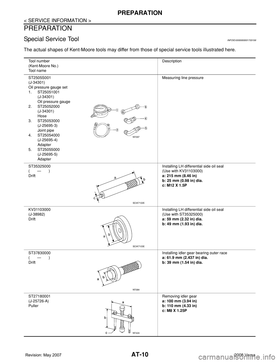
Special Service ToolINFOID:0000000001703156
The actual shapes of Kent-Moore tools may differ from those of special service tools illustrated here.
Tool number
(Kent-Moore No.)
Tool nameDescription
ST2505S001
(J-34301)
Oil pressure gauge set
1. ST25051001
(J-34301)
Oil pressure gauge
2. ST25052000
(J-34301)
Hose
3. ST25053000
(J-25695-3)
Joint pipe
4. ST25054000
(J-25695-4)
Adapter
5. ST25055000
(J-25695-5)
AdapterMeasuring line pressure
ST35325000
( — )
DriftInstalling LH differential side oil seal
(Use with KV31103000)
a: 215 mm (8.46 in)
b: 25 mm (0.98 in) dia.
c: M12 X 1.5P
KV31103000
(J-38982)
DriftInstalling LH differential side oil seal
(Use with ST35325000)
a: 59 mm (2.32 in) dia.
b: 49 mm (1.93 in) dia.
ST37830000
( — )
DriftInstalling idler gear bearing outer race
a: 61.9 mm (2.437 in) dia.
b: 39 mm (1.54 in) dia.
ST27180001
(J-25726-A)
PullerRemoving idler gear
a: 100 mm (3.94 in)
b: 110 mm (4.33 in)
c: M8 X 1.25P
NT097
SCIA7102E
SCIA7103E
NT084
NT424
Page 23 of 2771
PREPARATION
AT-11
< SERVICE INFORMATION >
D
E
F
G
H
I
J
K
L
MA
B
AT
N
O
P
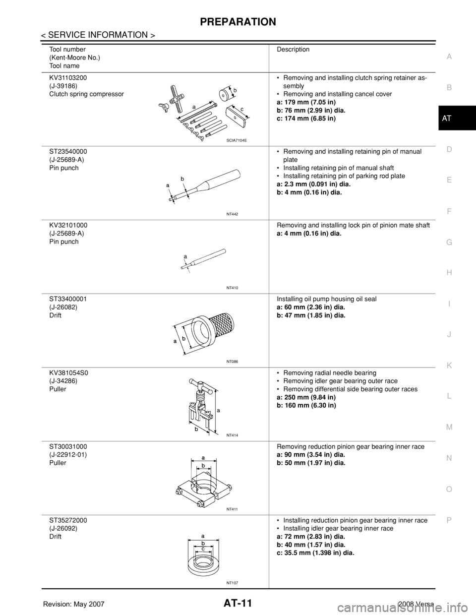
KV31103200
(J-39186)
Clutch spring compressor• Removing and installing clutch spring retainer as-
sembly
• Removing and installing cancel cover
a: 179 mm (7.05 in)
b: 76 mm (2.99 in) dia.
c: 174 mm (6.85 in)
ST23540000
(J-25689-A)
Pin punch• Removing and installing retaining pin of manual
plate
• Installing retaining pin of manual shaft
• Installing retaining pin of parking rod plate
a: 2.3 mm (0.091 in) dia.
b: 4 mm (0.16 in) dia.
KV32101000
(J-25689-A)
Pin punchRemoving and installing lock pin of pinion mate shaft
a: 4 mm (0.16 in) dia.
ST33400001
(J-26082)
DriftInstalling oil pump housing oil seal
a: 60 mm (2.36 in) dia.
b: 47 mm (1.85 in) dia.
KV381054S0
(J-34286)
Puller• Removing radial needle bearing
• Removing idler gear bearing outer race
• Removing differential side bearing outer races
a: 250 mm (9.84 in)
b: 160 mm (6.30 in)
ST30031000
(J-22912-01)
PullerRemoving reduction pinion gear bearing inner race
a: 90 mm (3.54 in) dia.
b: 50 mm (1.97 in) dia.
ST35272000
(J-26092)
Drift• Installing reduction pinion gear bearing inner race
• Installing idler gear bearing inner race
a: 72 mm (2.83 in) dia.
b: 40 mm (1.57 in) dia.
c: 35.5 mm (1.398 in) dia. Tool number
(Kent-Moore No.)
Tool nameDescription
SCIA7104E
NT442
NT410
NT086
NT414
NT411
NT107
Page 24 of 2771
AT-12
< SERVICE INFORMATION >
PREPARATION
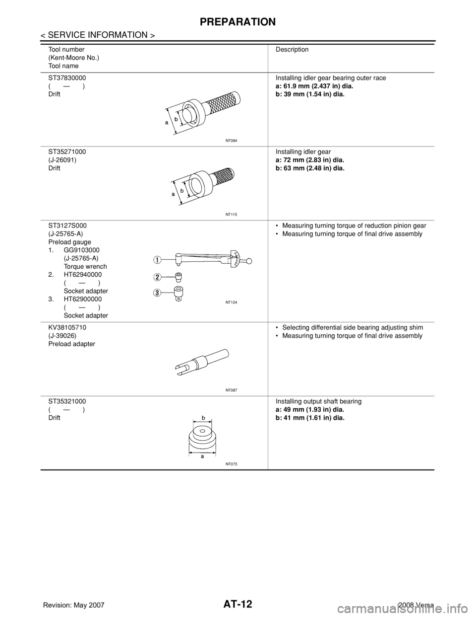
ST37830000
( — )
DriftInstalling idler gear bearing outer race
a: 61.9 mm (2.437 in) dia.
b: 39 mm (1.54 in) dia.
ST35271000
(J-26091)
DriftInstalling idler gear
a: 72 mm (2.83 in) dia.
b: 63 mm (2.48 in) dia.
ST3127S000
(J-25765-A)
Preload gauge
1. GG9103000
(J-25765-A)
Torque wrench
2. HT62940000
( — )
Socket adapter
3. HT62900000
( — )
Socket adapter• Measuring turning torque of reduction pinion gear
• Measuring turning torque of final drive assembly
KV38105710
(J-39026)
Preload adapter• Selecting differential side bearing adjusting shim
• Measuring turning torque of final drive assembly
ST35321000
( — )
DriftInstalling output shaft bearing
a: 49 mm (1.93 in) dia.
b: 41 mm (1.61 in) dia. Tool number
(Kent-Moore No.)
Tool nameDescription
NT084
NT115
NT124
NT087
NT073
Page 25 of 2771
PREPARATION
AT-13
< SERVICE INFORMATION >
D
E
F
G
H
I
J
K
L
MA
B
AT
N
O
P
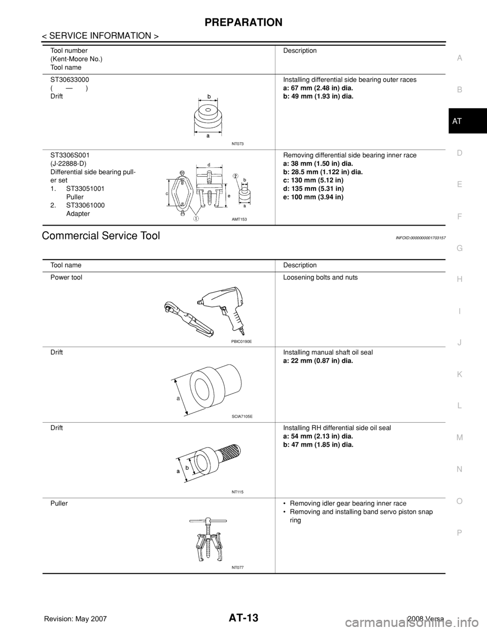
Commercial Service ToolINFOID:0000000001703157
ST30633000
( — )
DriftInstalling differential side bearing outer races
a: 67 mm (2.48 in) dia.
b: 49 mm (1.93 in) dia.
ST3306S001
(J-22888-D)
Differential side bearing pull-
er set
1. ST33051001
Puller
2. ST33061000
AdapterRemoving differential side bearing inner race
a: 38 mm (1.50 in) dia.
b: 28.5 mm (1.122 in) dia.
c: 130 mm (5.12 in)
d: 135 mm (5.31 in)
e: 100 mm (3.94 in) Tool number
(Kent-Moore No.)
Tool nameDescription
NT073
AMT153
Tool name Description
Power tool Loosening bolts and nuts
DriftInstalling manual shaft oil seal
a: 22 mm (0.87 in) dia.
DriftInstalling RH differential side oil seal
a: 54 mm (2.13 in) dia.
b: 47 mm (1.85 in) dia.
Puller• Removing idler gear bearing inner race
• Removing and installing band servo piston snap
ring
PBIC0190E
SCIA7105E
NT115
NT077
Page 26 of 2771
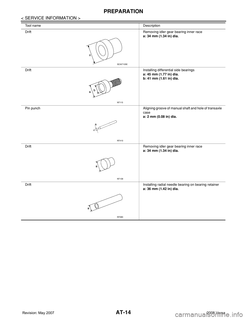
AT-14
< SERVICE INFORMATION >
PREPARATION
DriftRemoving idler gear bearing inner race
a: 34 mm (1.34 in) dia.
DriftInstalling differential side bearings
a: 45 mm (1.77 in) dia.
b: 41 mm (1.61 in) dia.
Pin punch Aligning groove of manual shaft and hole of transaxle
case
a: 2 mm (0.08 in) dia.
DriftRemoving idler gear bearing inner race
a: 34 mm (1.34 in) dia.
DriftInstalling radial needle bearing on bearing retainer
a: 36 mm (1.42 in) dia. Tool name Description
SCIA7105E
NT115
NT410
NT109
NT083
Page 31 of 2771
A/T CONTROL SYSTEM
AT-19
< SERVICE INFORMATION >
D
E
F
G
H
I
J
K
L
MA
B
AT
N
O
P
A/T CONTROL SYSTEM
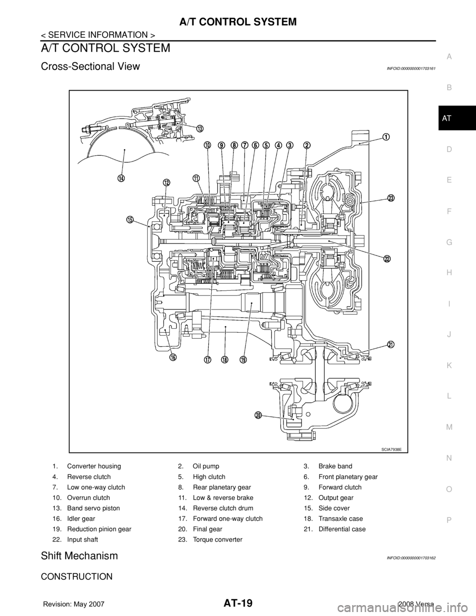
Cross-Sectional ViewINFOID:0000000001703161
Shift MechanismINFOID:0000000001703162
CONSTRUCTION
1. Converter housing 2. Oil pump 3. Brake band
4. Reverse clutch 5. High clutch 6. Front planetary gear
7. Low one-way clutch 8. Rear planetary gear 9. Forward clutch
10. Overrun clutch 11. Low & reverse brake 12. Output gear
13. Band servo piston 14. Reverse clutch drum 15. Side cover
16. Idler gear 17. Forward one-way clutch 18. Transaxle case
19. Reduction pinion gear 20. Final gear 21. Differential case
22. Input shaft 23. Torque converter
SCIA7938E