Page 258 of 2771
AT-246
< SERVICE INFORMATION >
DISASSEMBLY
27. Remove RH differential side oil seal from converter housing
using a flat-bladed screwdriver.
CAUTION:
Be careful not to scratch converter housing.
28. Remove differential lubricant tube (1) and clips (2) from con-
verter housing.
: Bolt (3)
29. Remove oil pump assembly according to the following procedures.
a. Remove O-ring from input shaft assembly (high clutch drum).
b. Remove oil pump assembly fitting bolts, and then remove oil
pump assembly (1) from transaxle case.
c. Remove O-ring from oil pump assembly (1).
SCIA3283E
SCIA7817E
SCIA5634E
SCIA6036J
Page 268 of 2771
AT-256
< SERVICE INFORMATION >
DISASSEMBLY
48. Remove return spring (2) from parking shaft (3) using a flat-
bladed screwdriver.
(1): Parking pawl
•Inspect return spring (2), and replace if damaged or worn.
49. Draw out parking shaft (1), and then remove parking pawl (2)
from transaxle case.
•Inspect parking shaft (1) and parking pawl (2), and replace
if damaged or worn.
50. Remove parking actuator support (1) from transaxle case.
•Inspect parking actuator support (1), and replace if dam-
aged or worn.
51. Remove snap ring from transaxle case using a flat-bladed
screwdriver.
52. Remove governor cap from transaxle case.
53. Remove O-ring from governor cap.
54. Remove LH differential side oil seal from transaxle case using a
flat-bladed screwdriver.
CAUTION:
Be careful not to scratch transaxle case.
SCIA6996E
SCIA6997E
SCIA6998E
ATM0076D
Page 325 of 2771
REPAIR FOR COMPONENT PARTS
AT-313
< SERVICE INFORMATION >
D
E
F
G
H
I
J
K
L
MA
B
AT
N
O
P
11. Push in OD servo piston assembly using a puller A (commercial
service tool) and a suitable drift B, and install snap ring (1) to
transaxle case using a flat-bladed screwdriver C.
Final DriveINFOID:0000000001703390
COMPONENTS
DISASSEMBLY
1. Remove final gear (1) from differential case (2).
SCIA7050E
1. Pinion mate gear 2. Pinion mate gear thrust washer 3. Pinion mate shaft
4. Lock pin 5. Side gear 6. Side gear thrust washer
7. Differential side bearing 8. Speedometer drive gear 9. Differential case
10. Final gear 11. Differential side bearing 12. Differential side bearing adjusting
shim
Refer to GI section to make sure icons (symbol marks) in the figure. Refer to GI-8, "
Component".
SCIA7962E
SCIA8003E
Page 326 of 2771
AT-314
< SERVICE INFORMATION >
REPAIR FOR COMPONENT PARTS
2. Press out differential side bearings.
CAUTION:
Be careful not to mix up the right and left bearings.
3. Remove speedometer drive gear from differential case.
4. Drive out lock pin from differential case (1) using Tool (A).
5. Draw out pinion mate shaft.
6. Remove pinion mate gears, pinion mate gear thrust washers,
side gears and side gear thrust washers.
INSPECTION
Gears, Washers, Pinion Mate Shaft and Differential Case
Tool number: ST3306S001 (J-22888-D)
SAT312D
SAT313D
Tool number: KV32101000 (J-25689-A)
SCIA7034E
SAT316D
Page 327 of 2771
REPAIR FOR COMPONENT PARTS
AT-315
< SERVICE INFORMATION >
D
E
F
G
H
I
J
K
L
MA
B
AT
N
O
P
• Check mating surfaces of differential case, side gears, pinion mate
gears and pinion mate shaft. Replace if necessary.
• Check washers for wear. Replace if necessary.
Bearings
• Make sure bearings roll freely and are free from noise, cracks, pit-
ting or wear. Replace if necessary.
CAUTION:
When replacing taper roller bearing, replace outer and inner
race as a set.
ASSEMBLY
1. Attach side gear thrust washers to side gears, then install pinion
mate thrust washers and pinion mate gears in place.
CAUTION:
Apply ATF to any parts.
2. Insert pinion mate shaft.
CAUTION:
• When inserting, be careful not to damage pinion mate
gear thrust washers.
• Apply ATF to pinion mate shaft.
3. Select side gear thrust washers according to the following procedures.
SAT544F
SPD715
SMT839
SMT087A
Page 328 of 2771

AT-316
< SERVICE INFORMATION >
REPAIR FOR COMPONENT PARTS
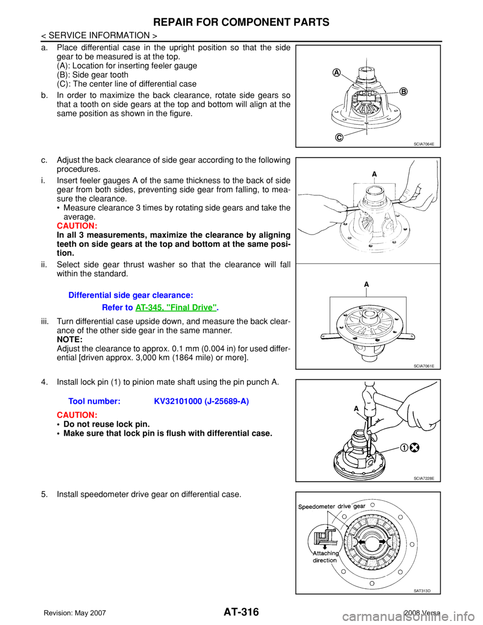
a. Place differential case in the upright position so that the side
gear to be measured is at the top.
(A): Location for inserting feeler gauge
(B): Side gear tooth
(C): The center line of differential case
b. In order to maximize the back clearance, rotate side gears so
that a tooth on side gears at the top and bottom will align at the
same position as shown in the figure.
c. Adjust the back clearance of side gear according to the following
procedures.
i. Insert feeler gauges A of the same thickness to the back of side
gear from both sides, preventing side gear from falling, to mea-
sure the clearance.
• Measure clearance 3 times by rotating side gears and take the
average.
CAUTION:
In all 3 measurements, maximize the clearance by aligning
teeth on side gears at the top and bottom at the same posi-
tion.
ii. Select side gear thrust washer so that the clearance will fall
within the standard.
iii. Turn differential case upside down, and measure the back clear-
ance of the other side gear in the same manner.
NOTE:
Adjust the clearance to approx. 0.1 mm (0.004 in) for used differ-
ential [driven approx. 3,000 km (1864 mile) or more].
4. Install lock pin (1) to pinion mate shaft using the pin punch A.
CAUTION:
• Do not reuse lock pin.
• Make sure that lock pin is flush with differential case.
5. Install speedometer drive gear on differential case.
SCIA7064E
Differential side gear clearance:
Refer to AT-345, "
Final Drive".
SCIA7061E
Tool number: KV32101000 (J-25689-A)
SCIA7228E
SAT313D
Page 329 of 2771
REPAIR FOR COMPONENT PARTS
AT-317
< SERVICE INFORMATION >
D
E
F
G
H
I
J
K
L
MA
B
AT
N
O
P
6. Set drift A [commercial service tool] on differential side bearing
inner race, and press differential side bearing inner race into dif-
ferential case.
CAUTION:
Apply ATF to differential side bearings.
7. Install differential side bearing outer race and differential side
bearing adjusting shim on transaxle case. Refer to AT-318,
"Assembly (1)".
8. Tighten final gear and tighten fixing bolts to the specified torque
in numerical order as shown in the figure after temporarily tight-
ening them. Refer to "COMPONENTS".
SCIA8005E
SCIA8004E
Page 330 of 2771

AT-318
< SERVICE INFORMATION >
ASSEMBLY
ASSEMBLY
Assembly (1)INFOID:0000000001703391
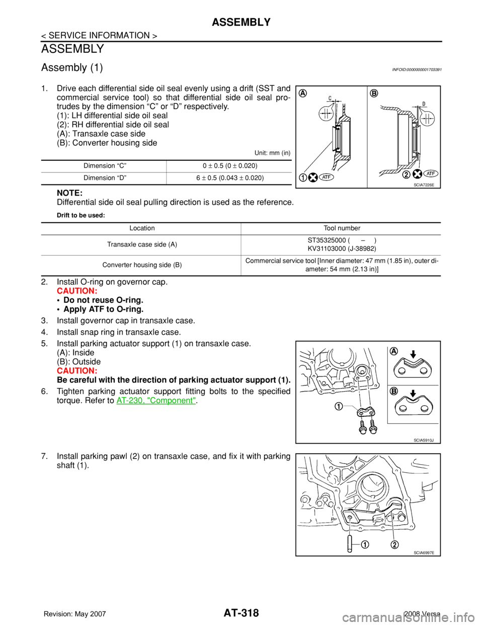
1. Drive each differential side oil seal evenly using a drift (SST and
commercial service tool) so that differential side oil seal pro-
trudes by the dimension “C” or “D” respectively.
(1): LH differential side oil seal
(2): RH differential side oil seal
(A): Transaxle case side
(B): Converter housing side
Unit: mm (in)
NOTE:
Differential side oil seal pulling direction is used as the reference.
Drift to be used:
2. Install O-ring on governor cap.
CAUTION:
• Do not reuse O-ring.
• Apply ATF to O-ring.
3. Install governor cap in transaxle case.
4. Install snap ring in transaxle case.
5. Install parking actuator support (1) on transaxle case.
(A): Inside
(B): Outside
CAUTION:
Be careful with the direction of parking actuator support (1).
6. Tighten parking actuator support fitting bolts to the specified
torque. Refer to AT-230, "
Component".
7. Install parking pawl (2) on transaxle case, and fix it with parking
shaft (1).
Dimension “C” 0 ± 0.5 (0 ± 0.020)
Dimension “D” 6 ± 0.5 (0.043 ± 0.020)
SCIA7226E
Location Tool number
Transaxle case side (A)ST35325000 ( – )
KV31103000 (J-38982)
Converter housing side (B)Commercial service tool [Inner diameter: 47 mm (1.85 in), outer di-
ameter: 54 mm (2.13 in)]
SCIA5910J
SCIA6997E