2008 NISSAN LATIO ESP inoperative
[x] Cancel search: ESP inoperativePage 560 of 2771

BL-126
< SERVICE INFORMATION >
INTELLIGENT KEY SYSTEM
NG >> Repair or replace Intelligent Key warning buzzer power supply circuit.
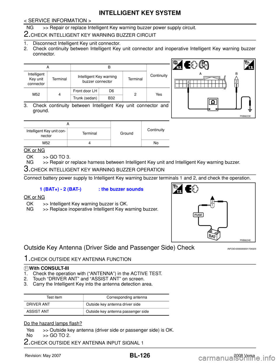
2.CHECK INTELLIGENT KEY WARNING BUZZER CIRCUIT
1. Disconnect Intelligent Key unit connector.
2. Check continuity between Intelligent Key unit connector and inoperative Intelligent Key warning buzzer
connector.
3. Check continuity between Intelligent Key unit connector and
ground.
OK or NG
OK >> GO TO 3.
NG >> Repair or replace harness between Intelligent Key unit and Intelligent Key warning buzzer.
3.CHECK INTELLIGENT KEY WARNING BUZZER OPERATION
Connect battery power supply to Intelligent Key warning buzzer terminals 1 and 2, and check the operation.
OK or NG
OK >> Intelligent Key warning buzzer is OK.
NG >> Replace inoperative Intelligent Key warning buzzer.
Outside Key Antenna (Driver Side and Passenger Side) CheckINFOID:0000000001704025
1.CHECK OUTSIDE KEY ANTENNA FUNCTION
With CONSULT-III
1. Check the operation with (“ANTENNA”) in the ACTIVE TEST.
2. Touch “DRIVER ANT” and “ASSIST ANT” on screen.
3. Carry the Intelligent Key into the antenna detection area.
Do the hazard lamps flash?
Yes >> Outside key antenna (driver side or passenger side) is OK.
No >> GO TO 2.
2.CHECK OUTSIDE KEY ANTENNA INPUT SIGNAL 1
AB
Continuity Intelligent
Key unit
connectorTe r m i n a lIntelligent Key warning
buzzer connectorTe r m i n a l
M52 4Front door LH D6
2Yes
Trunk (sedan) B32
A
GroundContinuity
Intelligent Key unit con-
nectorTerminal
M52 4 No
PIIB6623E
1 (BAT+) - 2 (BAT-) : the buzzer sounds
PIIB6624E
Test item Corresponding antenna
DRIVER ANT Outside key antenna driver side
ASSIST ANT Outside key antenna passenger side
Page 1090 of 2771

EC-16
< SERVICE INFORMATION >
PRECAUTIONS
PRECAUTIONS
Precaution for Supplemental Restraint System (SRS) "AIR BAG" and "SEAT BELT
PRE-TENSIONER"
INFOID:0000000001702548
The Supplemental Restraint System such as “AIR BAG” and “SEAT BELT PRE-TENSIONER”, used along
with a front seat belt, helps to reduce the risk or severity of injury to the driver and front passenger for certain
types of collision. This system includes seat belt switch inputs and dual stage front air bag modules. The SRS
system uses the seat belt switches to determine the front air bag deployment, and may only deploy one front
air bag, depending on the severity of a collision and whether the front occupants are belted or unbelted.
Information necessary to service the system safely is included in the SRS and SB section of this Service Man-
ual.
WARNING:
• To avoid rendering the SRS inoperative, which could increase the risk of personal injury or death in
the event of a collision which would result in air bag inflation, all maintenance must be performed by
an authorized NISSAN/INFINITI dealer.
• Improper maintenance, including incorrect removal and installation of the SRS, can lead to personal
injury caused by unintentional activation of the system. For removal of Spiral Cable and Air Bag
Module, see the SRS section.
• Do not use electrical test equipment on any circuit related to the SRS unless instructed to in this
Service Manual. SRS wiring harnesses can be identified by yellow and/or orange harnesses or har-
ness connectors.
Precaution for Procedure without Cowl Top CoverINFOID:0000000001702549
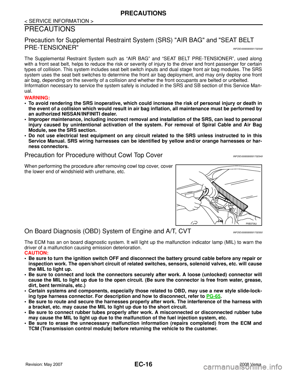
When performing the procedure after removing cowl top cover, cover
the lower end of windshield with urethane, etc.
On Board Diagnosis (OBD) System of Engine and A/T, CVTINFOID:0000000001702550
The ECM has an on board diagnostic system. It will light up the malfunction indicator lamp (MIL) to warn the
driver of a malfunction causing emission deterioration.
CAUTION:
• Be sure to turn the ignition switch OFF and disconnect the battery ground cable before any repair or
inspection work. The open/short circuit of related switches, sensors, solenoid valves, etc. will cause
the MIL to light up.
• Be sure to connect and lock the connectors securely after work. A loose (unlocked) connector will
cause the MIL to light up due to the open circuit. (Be sure the connector is free from water, grease,
dirt, bent terminals, etc.)
• Certain systems and components, especially those related to OBD, may use a new style slide-lock-
ing type harness connector. For description and how to disconnect, refer to PG-65
.
• Be sure to route and secure the harnesses properly after work. The interference of the harness with
a bracket, etc. may cause the MIL to light up due to the short circuit.
• Be sure to connect rubber tubes properly after work. A misconnected or disconnected rubber tube
may cause the MIL to light up due to the malfunction of the fuel injection system, etc.
• Be sure to erase the unnecessary malfunction information (repairs completed) from the ECM and
TCM (Transmission control module) before returning the vehicle to the customer.
PIIB3706J
Page 2200 of 2771

COMBINATION SWITCH
LT-63
< SERVICE INFORMATION >
C
D
E
F
G
H
I
J
L
MA
B
LT
N
O
P
Terminal and Reference Value for BCMINFOID:0000000001704434
Refer to BCS-11, "Terminal and Reference Value for BCM" .
CONSULT-III Function (BCM)INFOID:0000000001704435
Refer to LT- 11 , "CONSULT-III Function (BCM)" .
Combination Switch InspectionINFOID:0000000001704436
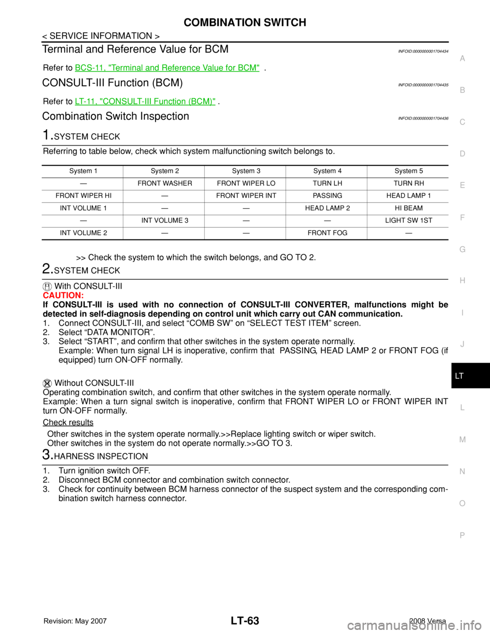
1.SYSTEM CHECK
Referring to table below, check which system malfunctioning switch belongs to.
>> Check the system to which the switch belongs, and GO TO 2.
2.SYSTEM CHECK
With CONSULT-III
CAUTION:
If CONSULT-III is used with no connection of CONSULT-III CONVERTER, malfunctions might be
detected in self-diagnosis depending on control unit which carry out CAN communication.
1. Connect CONSULT-III, and select “COMB SW” on “SELECT TEST ITEM” screen.
2. Select “DATA MONITOR”.
3. Select “START”, and confirm that other switches in the system operate normally.
Example: When turn signal LH is inoperative, confirm that PASSING, HEAD LAMP 2 or FRONT FOG (if
equipped) turn ON-OFF normally.
Without CONSULT-III
Operating combination switch, and confirm that other switches in the system operate normally.
Example: When a turn signal switch is inoperative, confirm that FRONT WIPER LO or FRONT WIPER INT
turn ON-OFF normally.
Check results
Other switches in the system operate normally.>>Replace lighting switch or wiper switch.
Other switches in the system do not operate normally.>>GO TO 3.
3.HARNESS INSPECTION
1. Turn ignition switch OFF.
2. Disconnect BCM connector and combination switch connector.
3. Check for continuity between BCM harness connector of the suspect system and the corresponding com-
bination switch harness connector.
System 1 System 2 System 3 System 4 System 5
— FRONT WASHER FRONT WIPER LO TURN LH TURN RH
FRONT WIPER HI — FRONT WIPER INT PASSING HEAD LAMP 1
INT VOLUME 1 — — HEAD LAMP 2 HI BEAM
— INT VOLUME 3 — — LIGHT SW 1ST
INT VOLUME 2 — — FRONT FOG —