2008 NISSAN LATIO wiring diagram
[x] Cancel search: wiring diagramPage 13 of 2771

AT-1
TRANSMISSION/TRANSAXLE
D
E
F
G
H
I
J
K
L
M
SECTION AT
A
B
AT
N
O
P
CONTENTS
AUTOMATIC TRANSAXLE
SERVICE INFORMATION ............................5
INDEX FOR DTC .................................................5
Alphabetical Index .....................................................5
DTC No. Index ..........................................................5
PRECAUTIONS ...................................................7
Precaution for Supplemental Restraint System
(SRS) "AIR BAG" and "SEAT BELT PRE-TEN-
SIONER" ...................................................................
7
Precaution Necessary for Steering Wheel Rota-
tion After Battery Disconnect .....................................
7
Precaution for On Board Diagnosis (OBD) System
of A/T and Engine .....................................................
7
Precaution .................................................................8
Service Notice or Precaution .....................................9
PREPARATION ..................................................10
Special Service Tool ...............................................10
Commercial Service Tool ........................................13
A/T FLUID ...........................................................15
Checking A/T Fluid ..................................................15
Changing A/T Fluid .................................................15
A/T Fluid Cooler Cleaning .......................................16
A/T CONTROL SYSTEM ....................................19
Cross-Sectional View ..............................................19
Shift Mechanism ......................................................19
TCM Function ..........................................................27
CAN Communication ...............................................28
Input/Output Signal of TCM .....................................28
Line Pressure Control .............................................29
Shift Control ............................................................30
Lock-up Control .......................................................31
Engine Brake Control (Overrun Clutch Control) ......32
Control Valve ...........................................................34
Centrifugal Cancel Mechanism ...............................34
ON BOARD DIAGNOSTIC (OBD) SYSTEM ......36
Introduction .............................................................36
OBD-II Function for A/T System ..............................36
One or Two Trip Detection Logic of OBD-II .............36
OBD-II Diagnostic Trouble Code (DTC) ..................36
Malfunction Indicator Lamp (MIL) ............................38
TROUBLE DIAGNOSIS ....................................39
DTC Inspection Priority Chart ..................................39
Fail-Safe ..................................................................39
How to Perform Trouble Diagnosis for Quick and
Accurate Repair .......................................................
40
A/T Electrical Parts Location ...................................46
Circuit Diagram ........................................................47
Inspections Before Trouble Diagnosis .....................48
Road Test ................................................................52
Check Before Engine Is Started ..............................53
Check at Idle ............................................................53
Cruise Test - Part 1 .................................................55
Cruise Test - Part 2 .................................................58
Cruise Test - Part 3 .................................................59
Vehicle Speed at Which Gear Shifting Occurs ........61
Vehicle Speed at Which Lock-up Occurs/Releas-
es .............................................................................
61
Symptom Chart ........................................................61
TCM Terminal and Reference Value .......................71
CONSULT-III Function (A/T) ...................................73
Diagnosis Procedure without CONSULT-III ............78
DTC U1000 CAN COMMUNICATION LINE .....83
Description ...............................................................83
On Board Diagnosis Logic .......................................83
Possible Cause ........................................................83
DTC Confirmation Procedure ..................................83
Wiring Diagram - AT - CAN .....................................84
Diagnosis Procedure ...............................................85
DTC P0705 PARK/NEUTRAL POSITION
(PNP) SWITCH ..................................................
86
Description ...............................................................86
CONSULT-III Reference Value in Data Monitor
Mode ........................................................................
86
On Board Diagnosis Logic .......................................86
Possible Cause ........................................................86
Page 14 of 2771

AT-2
DTC Confirmation Procedure .................................86
Wiring Diagram - AT - PNP/SW ..............................87
Diagnosis Procedure ..............................................88
Component Inspection ............................................90
DTC P0710 A/T FLUID TEMPERATURE SEN-
SOR CIRCUIT ....................................................
91
Description ..............................................................91
CONSULT-III Reference Value in Data Monitor
Mode .......................................................................
91
On Board Diagnosis Logic ......................................91
Possible Cause .......................................................91
DTC Confirmation Procedure .................................91
Wiring Diagram - AT - FTS .....................................92
Diagnosis Procedure ..............................................92
Component Inspection ............................................95
DTC P0720 VEHICLE SPEED SENSOR A/T
(REVOLUTION SENSOR) .................................
96
Description ..............................................................96
CONSULT-III Reference Value in Data Monitor
Mode .......................................................................
96
On Board Diagnosis Logic ......................................96
Possible Cause .......................................................96
DTC Confirmation Procedure .................................96
Wiring Diagram - AT - VSSA/T ...............................97
Diagnosis Procedure ..............................................98
DTC P0725 ENGINE SPEED SIGNAL ............101
Description .............................................................101
CONSULT-III Reference Value in Data Monitor
Mode ......................................................................
101
On Board Diagnosis Logic .....................................101
Possible Cause ......................................................101
DTC Confirmation Procedure ................................101
Wiring Diagram - AT - ENGSS ..............................102
Diagnosis Procedure .............................................103
DTC P0731 A/T 1ST GEAR FUNCTION .........105
Description .............................................................105
On Board Diagnosis Logic .....................................105
Possible Cause ......................................................105
DTC Confirmation Procedure ................................105
Diagnosis Procedure .............................................106
DTC P0732 A/T 2ND GEAR FUNCTION .........108
Description .............................................................108
On Board Diagnosis Logic .....................................108
Possible Cause ......................................................108
DTC Confirmation Procedure ................................108
Diagnosis Procedure .............................................109
DTC P0733 A/T 3RD GEAR FUNCTION .........111
Description .............................................................111
On Board Diagnosis Logic .....................................111
Possible Cause ......................................................111
DTC Confirmation Procedure ................................111
Diagnosis Procedure .............................................112
DTC P0734 A/T 4TH GEAR FUNCTION .........114
Description ............................................................114
CONSULT-III Reference Value in Data Monitor
Mode .....................................................................
114
On Board Diagnosis Logic ....................................114
Possible Cause .....................................................114
DTC Confirmation Procedure ................................114
Diagnosis Procedure .............................................115
DTC P0740 TORQUE CONVERTER CLUTCH
SOLENOID VALVE ..........................................
119
Description ............................................................119
CONSULT-III Reference Value in Data Monitor
Mode .....................................................................
119
On Board Diagnosis Logic ....................................119
Possible Cause .....................................................119
DTC Confirmation Procedure ................................119
Wiring Diagram - AT - TCV ...................................120
Diagnosis Procedure .............................................121
Component Inspection ..........................................122
DTC P0744 A/T TCC S/V FUNCTION (LOCK-
UP) ....................................................................
124
Description ............................................................124
CONSULT-III Reference Value in Data Monitor
Mode .....................................................................
124
On Board Diagnosis Logic ....................................124
Possible Cause .....................................................124
DTC Confirmation Procedure ................................124
Diagnosis Procedure .............................................125
DTC P0745 LINE PRESSURE SOLENOID
VALVE ..............................................................
129
Description ............................................................129
CONSULT-III Reference Value in Data Monitor
Mode .....................................................................
129
On Board Diagnosis Logic ....................................129
Possible Cause .....................................................129
DTC Confirmation Procedure ................................129
Wiring Diagram - AT - LPSV .................................130
Diagnosis Procedure .............................................131
Component Inspection ..........................................133
DTC P0750 SHIFT SOLENOID VALVE A ........134
Description ............................................................134
CONSULT-III Reference Value in Data Monitor
Mode .....................................................................
134
On Board Diagnosis Logic ....................................134
Possible Cause .....................................................134
DTC Confirmation Procedure ................................134
Wiring Diagram - AT - SSV/A ................................135
Diagnosis Procedure .............................................136
Component Inspection ..........................................137
DTC P0755 SHIFT SOLENOID VALVE B ........139
Description ............................................................139
CONSULT-III Reference Value in Data Monitor
Mode .....................................................................
139
On Board Diagnosis Logic ....................................139
Possible Cause .....................................................139
DTC Confirmation Procedure ................................139
Page 15 of 2771

AT-3
D
E
F
G
H
I
J
K
L
MA
B
AT
N
O
P N Wiring Diagram - AT - SSV/B ................................
140
Diagnosis Procedure .............................................141
Component Inspection ..........................................142
DTC P1760 OVERRUN CLUTCH SOLENOID
VALVE ..............................................................
144
Description ............................................................144
CONSULT-III Reference Value in Data Monitor
Mode .....................................................................
144
On Board Diagnosis Logic ....................................144
Possible Cause .....................................................144
DTC Confirmation Procedure ................................144
Wiring Diagram - AT - OVRCSV ...........................145
Diagnosis Procedure .............................................146
Component Inspection ..........................................147
DTC VEHICLE SPEED SENSOR MTR ............149
Description ............................................................149
CONSULT-III Reference Value in Data Monitor
Mode .....................................................................
149
On Board Diagnosis Logic ....................................149
Possible Cause .....................................................149
DTC Confirmation Procedure ................................149
Wiring Diagram - AT - VSSMTR ...........................150
Diagnosis Procedure .............................................151
DTC BATT/FLUID TEMP SEN (A/T FLUID
TEMP SENSOR CIRCUIT AND TCM POWER
SOURCE) .........................................................
152
Description ............................................................152
CONSULT-III Reference Value in Data Monitor
Mode .....................................................................
152
On Board Diagnosis Logic ....................................152
Possible Cause .....................................................152
DTC Confirmation Procedure ................................152
Wiring Diagram - AT - BA/FTS ..............................153
Diagnosis Procedure .............................................154
Component Inspection ..........................................156
DTC TURBINE REVOLUTION SENSOR .........158
Description ............................................................158
CONSULT-III Reference Value in Data Monitor
Mode .....................................................................
158
On Board Diagnosis Logic ....................................158
Possible Cause .....................................................158
DTC Confirmation Procedure ................................158
Wiring Diagram - AT - PT/SEN .............................159
Diagnosis Procedure .............................................160
CONTROL UNIT (RAM), CONTROL UNIT
(ROM) ...............................................................
163
Description ............................................................163
On Board Diagnosis Logic ....................................163
Possible Cause .....................................................163
DTC Confirmation Procedure ................................163
Diagnosis Procedure .............................................163
MAIN POWER SUPPLY AND GROUND CIR-
CUIT ..................................................................
164
Wiring Diagram - AT - MAIN .................................164
Diagnosis Procedure .............................................165
PNP, OD SWITCH AND CLOSED THROT-
TLE, WIDE OPEN THROTTLE POSITION
SIGNAL CIRCUIT ............................................
167
CONSULT-III Reference Value in Data Monitor
Mode ......................................................................
167
TCM Terminal and Reference Value .....................167
Diagnosis Procedure .............................................167
Component Inspection ...........................................171
SHIFT POSITION INDICATOR CIRCUIT ........172
Description .............................................................172
CONSULT-III Reference Value in Data Monitor
Mode ......................................................................
172
Diagnosis Procedure .............................................172
TROUBLE DIAGNOSIS FOR SYMPTOMS ....173
Wiring Diagram - AT - NONDTC ...........................173
OD OFF Indicator Lamp Does Not Come On ........176
Engine Cannot Be Started in "P" and "N" Position ..178
In "P" Position, Vehicle Moves Forward or Back-
ward When Pushed ...............................................
179
In "N" Position, Vehicle Moves ..............................179
Large Shock "N" → "R" Position ............................180
Vehicle Does Not Creep Backward in "R" Position ..181
Vehicle Does Not Creep Forward in "D", "2" or "1"
Position ..................................................................
182
Vehicle Cannot Be Started from D1 .......................183
A/T Does Not Shift: D1→ D2or Does Not Kick-
down: D
4→ D2 .......................................................185
A/T Does Not Shift: D2→ D3 ..................................186
A/T Does Not Shift: D3→ D4 ..................................188
A/T Does Not Perform Lock-up .............................189
A/T Does Not Hold Lock-up Condition ...................190
Lock-up Is Not Released .......................................191
Engine Speed Does Not Return to Idle (Light
Braking D
4→ D3) ...................................................192
A/T Does Not Shift: D4→ D3, When OD OFF ........193
A/T Does Not Shift: D3→ 22, When Selector Lever
"D" → "2" Position .................................................
194
A/T Does Not Shift: 22→ 11, When Selector Lever
"2" → "1" Position ..................................................
195
Vehicle Does Not Decelerate by Engine Brake .....197
TCM Self-Diagnosis Does Not Activate .................200
TRANSMISSION CONTROL MODULE ..........202
Removal and Installation .......................................202
SHIFT CONTROL SYSTEM ............................203
Control Device Removal and Installation ...............203
Control Device Disassembly and Assembly ..........206
Selector Lever Knob Removal and Installation ......206
Adjustment of A/T Position ....................................207
Checking of A/T Position .......................................207
A/T SHIFT LOCK SYSTEM .............................209
Description .............................................................209
Shift Lock System Parts Location ..........................209
Wiring Diagram - AT - SHIFT ................................210
Page 40 of 2771
AT-28
< SERVICE INFORMATION >
A/T CONTROL SYSTEM
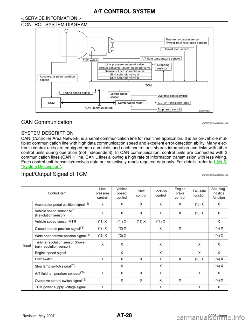
CONTROL SYSTEM DIAGRAM
CAN CommunicationINFOID:0000000001703164
SYSTEM DESCRIPTION
CAN (Controller Area Network) is a serial communication line for real time application. It is an on-vehicle mul-
tiplex communication line with high data communication speed and excellent error detection ability. Many elec-
tronic control units are equipped onto a vehicle, and each control unit shares information and links with other
control units during operation (not independent). In CAN communication, control units are connected with 2
communication lines (CAN H line, CAN L line) allowing a high rate of information transmission with less wiring.
Each control unit transmits/receives data but selectively reads required data only. For details, refer to LAN-6,
"System Description".
Input/Output Signal of TCMINFOID:0000000001703165
SCIA7112E
Control itemLine
pressure
controlVehicle
speed
controlShift
controlLock-up
controlEngine
brake
controlFail-safe
functionSelf-diag-
nostics
function
InputAccelerator pedal position signal
(*5)XXXXX(*3) XX
Vehicle speed sensor·A/T
(Revolution sensor)XXXXX(*3) XX
Vehicle speed sensor·MTR (*1) X (*1) X (*1) X (*1) X X
Closed throttle position signal
(*5)(*2) X (*2) X X X (*4) X
Wide open throttle position signal
(*5)(*2) X (*2) X (*4) X
Turbine revolution sensor (Power
train revolution sensor)XXXXX
Engine speed signal X X X X
PNP switch XXXXX(*3) X(*4) X
Stop lamp switch signal
(*5)XX (*4) X
A/T fluid temperature sensors
(*5)XXXX XX
Overdrive control switch signal
(*5)XXXX (*4) X
TCM power supply voltage signal X X X X
Page 96 of 2771
AT-84
< SERVICE INFORMATION >
DTC U1000 CAN COMMUNICATION LINE
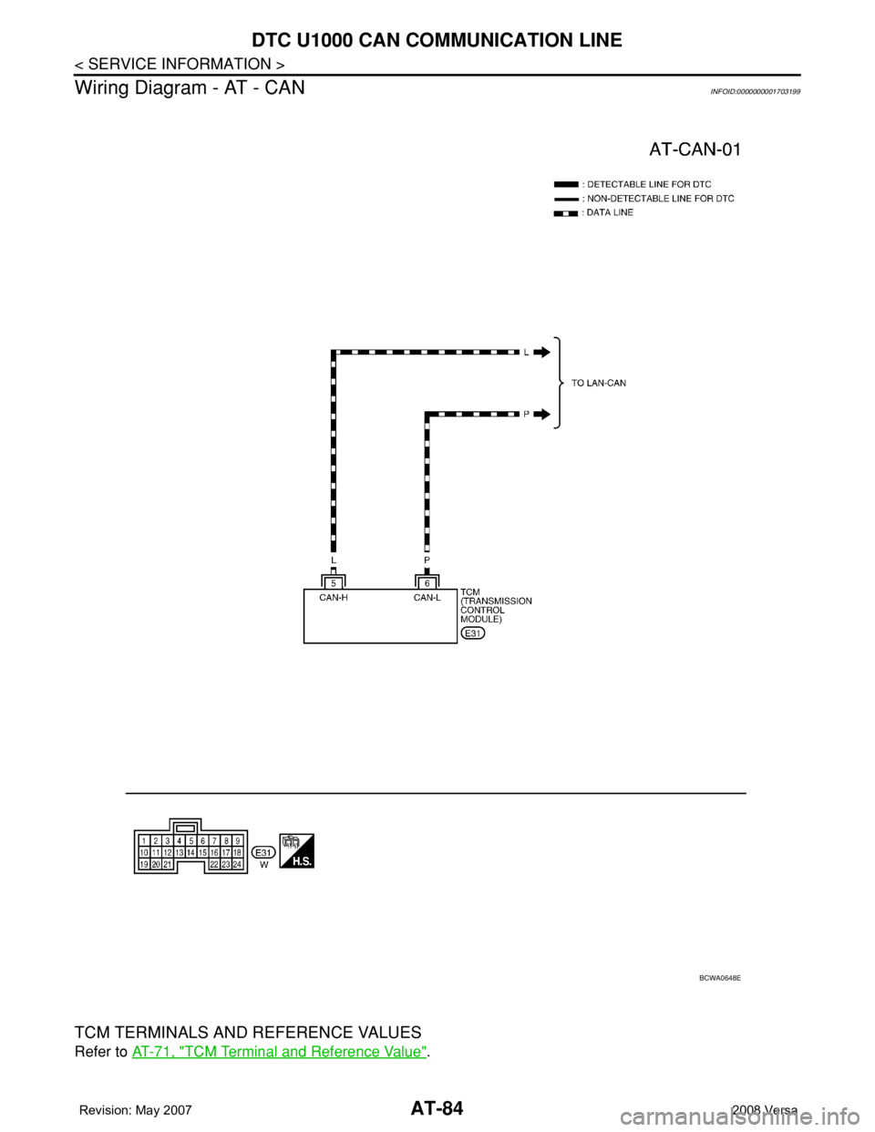
Wiring Diagram - AT - CAN
INFOID:0000000001703199
TCM TERMINALS AND REFERENCE VALUES
Refer to AT-71, "TCM Terminal and Reference Value".
BCWA0648E
Page 99 of 2771
DTC P0705 PARK/NEUTRAL POSITION (PNP) SWITCH
AT-87
< SERVICE INFORMATION >
D
E
F
G
H
I
J
K
L
MA
B
AT
N
O
P
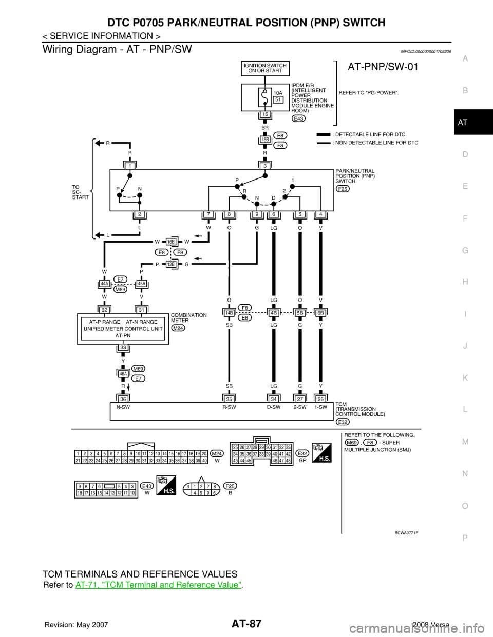
Wiring Diagram - AT - PNP/SWINFOID:0000000001703206
TCM TERMINALS AND REFERENCE VALUES
Refer to AT-71, "TCM Terminal and Reference Value".
BCWA0771E
Page 104 of 2771
AT-92
< SERVICE INFORMATION >
DTC P0710 A/T FLUID TEMPERATURE SENSOR CIRCUIT
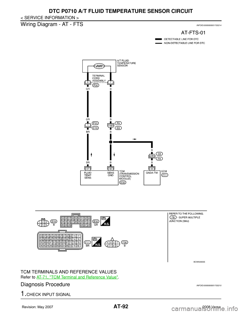
Wiring Diagram - AT - FTS
INFOID:0000000001703214
TCM TERMINALS AND REFERENCE VALUES
Refer to AT-71, "TCM Terminal and Reference Value".
Diagnosis ProcedureINFOID:0000000001703215
1.CHECK INPUT SIGNAL
BCWA0650E
Page 109 of 2771
DTC P0720 VEHICLE SPEED SENSOR A/T (REVOLUTION SENSOR)
AT-97
< SERVICE INFORMATION >
D
E
F
G
H
I
J
K
L
MA
B
AT
N
O
P
2. Drive vehicle under the following conditions for more than 5 seconds.
Selector lever position: “D” position
Vehicle speed: 30 km/h (19 MPH) or more
Throttle position: greater than 1.0/8 of the full throttle position
3. Perform self-diagnosis. Refer to AT-78, "
Diagnosis Procedure without CONSULT-III" .
4. If the check result is NG, go to AT-98, "
Diagnosis Procedure" .
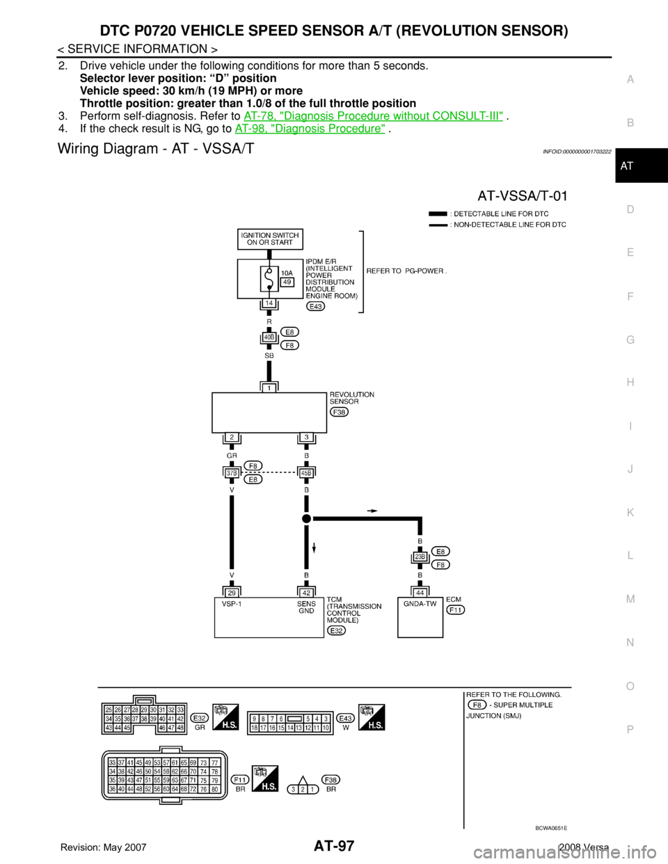
Wiring Diagram - AT - VSSA/TINFOID:0000000001703222
BCWA0651E