Page 128 of 2771

AT-116
< SERVICE INFORMATION >
DTC P0734 A/T 4TH GEAR FUNCTION
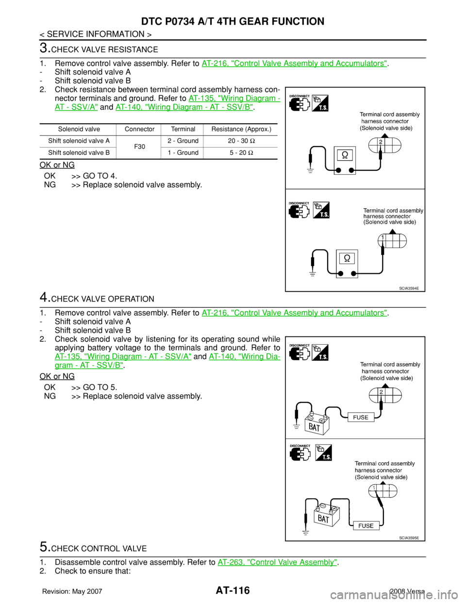
3.CHECK VALVE RESISTANCE
1. Remove control valve assembly. Refer to AT-216, "
Control Valve Assembly and Accumulators".
- Shift solenoid valve A
- Shift solenoid valve B
2. Check resistance between terminal cord assembly harness con-
nector terminals and ground. Refer to AT-135, "
Wiring Diagram -
AT - SSV/A" and AT-140, "Wiring Diagram - AT - SSV/B".
OK or NG
OK >> GO TO 4.
NG >> Replace solenoid valve assembly.
4.CHECK VALVE OPERATION
1. Remove control valve assembly. Refer to AT-216, "
Control Valve Assembly and Accumulators".
- Shift solenoid valve A
- Shift solenoid valve B
2. Check solenoid valve by listening for its operating sound while
applying battery voltage to the terminals and ground. Refer to
AT-135, "
Wiring Diagram - AT - SSV/A" and AT-140, "Wiring Dia-
gram - AT - SSV/B".
OK or NG
OK >> GO TO 5.
NG >> Replace solenoid valve assembly.
5.CHECK CONTROL VALVE
1. Disassemble control valve assembly. Refer to AT-263, "
Control Valve Assembly".
2. Check to ensure that:
Solenoid valve Connector Terminal Resistance (Approx.)
Shift solenoid valve A
F302 - Ground 20 - 30 Ω
Shift solenoid valve B 1 - Ground 5 - 20 Ω
SCIA3594E
SCIA3595E
Page 129 of 2771

DTC P0734 A/T 4TH GEAR FUNCTION
AT-117
< SERVICE INFORMATION >
D
E
F
G
H
I
J
K
L
MA
B
AT
N
O
P
- Valve, sleeve and plug slide along valve bore under their own weight.
- Valve, sleeve and plug are free from burrs, dents and scratches.
- Control valve springs are free from damage, deformation and fatigue.
- Hydraulic line is free from obstacles.
OK or NG
OK >> GO TO 6.
NG >> Repair control valve.
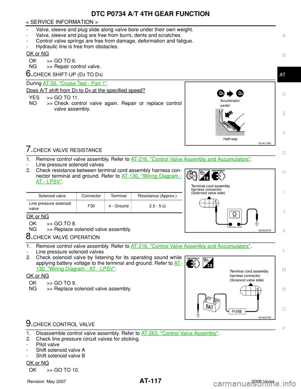
6.CHECK SHIFT-UP (D3 TO D4)
During AT-55, "
Cruise Test - Part 1".
Does A/T shift from D
3 to D4 at the specified speed?
YES >> GO TO 11.
NO >> Check control valve again. Repair or replace control
valve assembly.
7.CHECK VALVE RESISTANCE
1. Remove control valve assembly. Refer to AT-216, "
Control Valve Assembly and Accumulators".
- Line pressure solenoid valves
2. Check resistance between terminal cord assembly harness con-
nector terminal and ground. Refer to AT-130, "
Wiring Diagram -
AT - L P S V".
OK or NG
OK >> GO TO 8.
NG >> Replace solenoid valve assembly.
8.CHECK VALVE OPERATION
1. Remove control valve assembly. Refer to AT-216, "
Control Valve Assembly and Accumulators".
- Line pressure solenoid valves
2. Check solenoid valve by listening for its operating sound while
applying battery voltage to the terminal and ground. Refer to AT-
130, "Wiring Diagram - AT - LPSV".
OK or NG
OK >> GO TO 9.
NG >> Replace solenoid valve assembly.
9.CHECK CONTROL VALVE
1. Disassemble control valve assembly. Refer to AT-263, "
Control Valve Assembly".
2. Check line pressure circuit valves for sticking.
- Pilot valve
- Shift solenoid valve A
- Shift solenoid valve B
OK or NG
OK >> GO TO 10.
SCIA7190E
Solenoid valve Connector Terminal Resistance (Approx.)
Line pressure solenoid
valveF30 4 - Ground 2.5 - 5 Ω
SCIA3457E
SCIA3275E
Page 132 of 2771
AT-120
< SERVICE INFORMATION >
DTC P0740 TORQUE CONVERTER CLUTCH SOLENOID VALVE
Wiring Diagram - AT - TCV
INFOID:0000000001703257
TCM TERMINALS AND REFERENCE VALUES
Refer to AT-71, "TCM Terminal and Reference Value".
BCWA0653E
Page 138 of 2771

AT-126
< SERVICE INFORMATION >
DTC P0744 A/T TCC S/V FUNCTION (LOCK-UP)
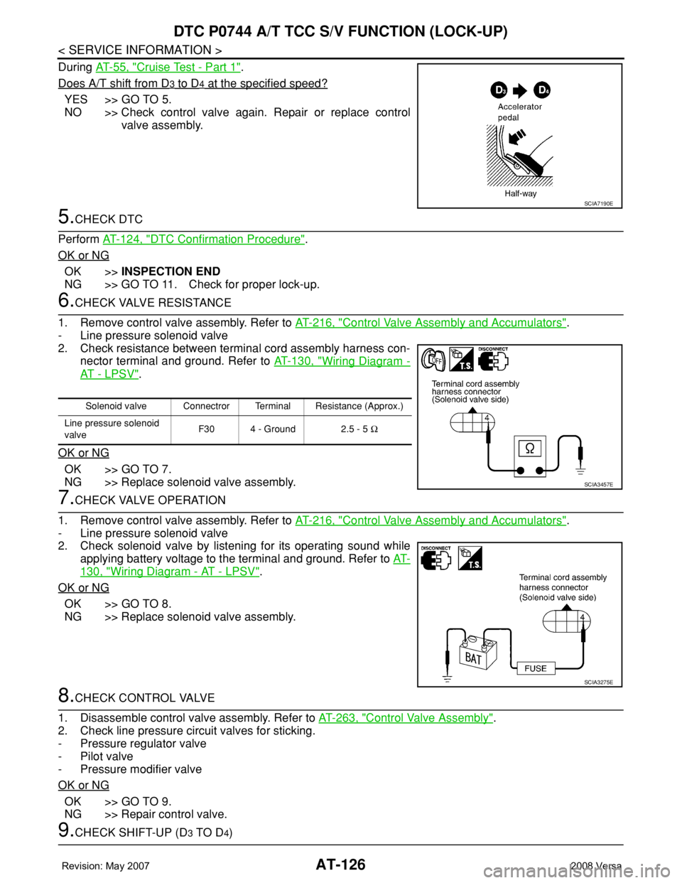
During AT-55, "Cruise Test - Part 1".
Does A/T shift from D
3 to D4 at the specified speed?
YES >> GO TO 5.
NO >> Check control valve again. Repair or replace control
valve assembly.
5.CHECK DTC
Perform AT-124, "
DTC Confirmation Procedure".
OK or NG
OK >>INSPECTION END
NG >> GO TO 11. Check for proper lock-up.
6.CHECK VALVE RESISTANCE
1. Remove control valve assembly. Refer to AT-216, "
Control Valve Assembly and Accumulators".
- Line pressure solenoid valve
2. Check resistance between terminal cord assembly harness con-
nector terminal and ground. Refer to AT-130, "
Wiring Diagram -
AT - L P S V".
OK or NG
OK >> GO TO 7.
NG >> Replace solenoid valve assembly.
7.CHECK VALVE OPERATION
1. Remove control valve assembly. Refer to AT-216, "
Control Valve Assembly and Accumulators".
- Line pressure solenoid valve
2. Check solenoid valve by listening for its operating sound while
applying battery voltage to the terminal and ground. Refer to AT-
130, "Wiring Diagram - AT - LPSV".
OK or NG
OK >> GO TO 8.
NG >> Replace solenoid valve assembly.
8.CHECK CONTROL VALVE
1. Disassemble control valve assembly. Refer to AT-263, "
Control Valve Assembly".
2. Check line pressure circuit valves for sticking.
- Pressure regulator valve
- Pilot valve
- Pressure modifier valve
OK or NG
OK >> GO TO 9.
NG >> Repair control valve.
9.CHECK SHIFT-UP (D3 TO D4)
SCIA7190E
Solenoid valve Connectror Terminal Resistance (Approx.)
Line pressure solenoid
valveF30 4 - Ground 2.5 - 5 Ω
SCIA3457E
SCIA3275E
Page 139 of 2771

DTC P0744 A/T TCC S/V FUNCTION (LOCK-UP)
AT-127
< SERVICE INFORMATION >
D
E
F
G
H
I
J
K
L
MA
B
AT
N
O
P
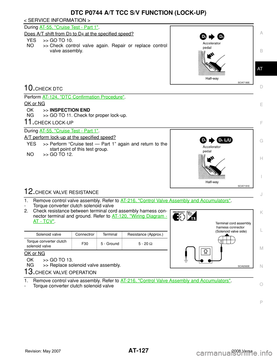
During AT-55, "Cruise Test - Part 1".
Does A/T shift from D
3 to D4 at the specified speed?
YES >> GO TO 10.
NO >> Check control valve again. Repair or replace control
valve assembly.
10.CHECK DTC
Perform AT-124, "
DTC Confirmation Procedure".
OK or NG
OK >>INSPECTION END
NG >> GO TO 11. Check for proper lock-up.
11 .CHECK LOCK-UP
During AT-55, "
Cruise Test - Part 1".
A/T perform lock-up at the specified speed?
YES >> Perform “Cruise test — Part 1” again and return to the
start point of this test group.
NO >> GO TO 12.
12.CHECK VALVE RESISTANCE
1. Remove control valve assembly. Refer to AT-216, "
Control Valve Assembly and Accumulators".
- Torque converter clutch solenoid valve
2. Check resistance between terminal cord assembly harness con-
nector terminal and ground. Refer to AT-120, "
Wiring Diagram -
AT - T C V".
OK or NG
OK >> GO TO 13.
NG >> Replace solenoid valve assembly.
13.CHECK VALVE OPERATION
1. Remove control valve assembly. Refer to AT-216, "
Control Valve Assembly and Accumulators".
- Torque converter clutch solenoid valve
SCIA7190E
SCIA7191E
Solenoid valve Connectror Terminal Resistance (Approx.)
Torque converter clutch
solenoid valveF30 5 - Ground 5 - 20 Ω
SCIA2063E
Page 140 of 2771
AT-128
< SERVICE INFORMATION >
DTC P0744 A/T TCC S/V FUNCTION (LOCK-UP)
2. Check solenoid valve by listening for its operating sound while
applying battery voltage to the terminal and ground. Refer to AT-
120, "Wiring Diagram - AT - TCV".
OK or NG
OK >> GO TO 14.
NG >> Replace solenoid valve assembly.
14.CHECK CONTROL VALVE
1. Disassemble control valve assembly. Refer to AT-263, "
Control Valve Assembly".
2. Check control valves for sticking.
- Torque converter clutch control valve
- Torque converter clutch relief valve
OK or NG
OK >> GO TO 15.
NG >> Repair control valve.
15.CHECK LOCK-UP
During AT-55, "
Cruise Test - Part 1".
A/T perform lock-up at the specified speed?
YES >> GO TO 16.
NO >> Check control valve again. Repair or replace control
valve assembly.
16.CHECK DTC
Perform AT-124, "
DTC Confirmation Procedure".
OK or NG
OK >>INSPECTION END
NG >> Perform “Cruise test — Part 1” again and return to the start point of this test group.
SCIA2066E
SCIA7191E
Page 142 of 2771
AT-130
< SERVICE INFORMATION >
DTC P0745 LINE PRESSURE SOLENOID VALVE
Wiring Diagram - AT - LPSV
INFOID:0000000001703271
TCM TERMINALS AND REFERENCE VALUES
Refer to AT-71, "TCM Terminal and Reference Value".
BCWA0654E
Page 147 of 2771
DTC P0750 SHIFT SOLENOID VALVE A
AT-135
< SERVICE INFORMATION >
D
E
F
G
H
I
J
K
L
MA
B
AT
N
O
P
Wiring Diagram - AT - SSV/AINFOID:0000000001703279
TCM TERMINALS AND REFERENCE VALUES
Refer to AT-71, "TCM Terminal and Reference Value".
BCWA0655E