2008 NISSAN LATIO battery location
[x] Cancel search: battery locationPage 13 of 2771

AT-1
TRANSMISSION/TRANSAXLE
D
E
F
G
H
I
J
K
L
M
SECTION AT
A
B
AT
N
O
P
CONTENTS
AUTOMATIC TRANSAXLE
SERVICE INFORMATION ............................5
INDEX FOR DTC .................................................5
Alphabetical Index .....................................................5
DTC No. Index ..........................................................5
PRECAUTIONS ...................................................7
Precaution for Supplemental Restraint System
(SRS) "AIR BAG" and "SEAT BELT PRE-TEN-
SIONER" ...................................................................
7
Precaution Necessary for Steering Wheel Rota-
tion After Battery Disconnect .....................................
7
Precaution for On Board Diagnosis (OBD) System
of A/T and Engine .....................................................
7
Precaution .................................................................8
Service Notice or Precaution .....................................9
PREPARATION ..................................................10
Special Service Tool ...............................................10
Commercial Service Tool ........................................13
A/T FLUID ...........................................................15
Checking A/T Fluid ..................................................15
Changing A/T Fluid .................................................15
A/T Fluid Cooler Cleaning .......................................16
A/T CONTROL SYSTEM ....................................19
Cross-Sectional View ..............................................19
Shift Mechanism ......................................................19
TCM Function ..........................................................27
CAN Communication ...............................................28
Input/Output Signal of TCM .....................................28
Line Pressure Control .............................................29
Shift Control ............................................................30
Lock-up Control .......................................................31
Engine Brake Control (Overrun Clutch Control) ......32
Control Valve ...........................................................34
Centrifugal Cancel Mechanism ...............................34
ON BOARD DIAGNOSTIC (OBD) SYSTEM ......36
Introduction .............................................................36
OBD-II Function for A/T System ..............................36
One or Two Trip Detection Logic of OBD-II .............36
OBD-II Diagnostic Trouble Code (DTC) ..................36
Malfunction Indicator Lamp (MIL) ............................38
TROUBLE DIAGNOSIS ....................................39
DTC Inspection Priority Chart ..................................39
Fail-Safe ..................................................................39
How to Perform Trouble Diagnosis for Quick and
Accurate Repair .......................................................
40
A/T Electrical Parts Location ...................................46
Circuit Diagram ........................................................47
Inspections Before Trouble Diagnosis .....................48
Road Test ................................................................52
Check Before Engine Is Started ..............................53
Check at Idle ............................................................53
Cruise Test - Part 1 .................................................55
Cruise Test - Part 2 .................................................58
Cruise Test - Part 3 .................................................59
Vehicle Speed at Which Gear Shifting Occurs ........61
Vehicle Speed at Which Lock-up Occurs/Releas-
es .............................................................................
61
Symptom Chart ........................................................61
TCM Terminal and Reference Value .......................71
CONSULT-III Function (A/T) ...................................73
Diagnosis Procedure without CONSULT-III ............78
DTC U1000 CAN COMMUNICATION LINE .....83
Description ...............................................................83
On Board Diagnosis Logic .......................................83
Possible Cause ........................................................83
DTC Confirmation Procedure ..................................83
Wiring Diagram - AT - CAN .....................................84
Diagnosis Procedure ...............................................85
DTC P0705 PARK/NEUTRAL POSITION
(PNP) SWITCH ..................................................
86
Description ...............................................................86
CONSULT-III Reference Value in Data Monitor
Mode ........................................................................
86
On Board Diagnosis Logic .......................................86
Possible Cause ........................................................86
Page 436 of 2771

BL-2
ID Code Entry Procedure .......................................71
Keyfob Battery Replacement ..................................73
Removal and Installation of Remote Keyless Entry
Receiver .................................................................
73
INTELLIGENT KEY SYSTEM ............................74
Component Parts and Harness Connector Loca-
tion ..........................................................................
74
System Description .................................................76
CAN Communication System Description ..............83
Schematic ...............................................................84
Wiring Diagram - I/KEY - ........................................86
Intelligent Key Unit Harness Connector Terminal
Layout .....................................................................
96
Terminal and Reference Value for Intelligent Key
Unit .........................................................................
96
Steering Lock Solenoid Harness Connector Ter-
minal Layout ...........................................................
98
Terminal and Reference Value for Steering Lock
Solenoid ..................................................................
98
Terminal and Reference Value for BCM .................99
Trouble Diagnosis Procedure .................................99
CONSULT-III Functions (INTELLIGENT KEY) ......100
CONSULT-III Application Item ...............................101
Trouble Diagnosis Symptom Chart ........................103
CAN Communication System Inspection ...............109
Power Supply and Ground Circuit Inspection ........110
Key Switch (Intelligent Key Unit Input) Check .......110
Key Switch (BCM Input) Check .............................112
Ignition Knob Switch Check ...................................113
Door Switch Check (Hatchback) ............................114
Door Switch Check (Sedan) ..................................117
Door Request Switch Check ..................................118
Back Door Request Switch Check (Hatchback) ....120
Trunk Opener Request Switch Check (Sedan) .....122
Unlock Sensor Check ............................................124
Intelligent Key Warning Buzzer(s) Check ..............125
Outside Key Antenna (Driver Side and Passenger
Side) Check ...........................................................
126
Outside Key Antenna (Rear Bumper) Check .........128
Inside Key Antenna Check ....................................129
Steering Lock Solenoid Check ..............................131
Key Interlock Solenoid (With M/T) Check ..............133
Ignition Switch Position Check ..............................134
Stop Lamp Switch Check (With CVT) ....................134
Stop Lamp Switch Check (With M/T) .....................135
Check CVT Device (Park Position Switch) Check ..136
"P-SHIFT" Warning Lamp (With CVT) Check ........138
"LOCK" Warning Lamp (With M/T) Check .............138
"KEY" Warning Lamp (RED) Check ......................139
"KEY" Warning Lamp (GREEN) Check .................139
Check Warning Chime in Combination Meter ........140
Hazard Function Check .........................................140
Horn Function Check .............................................140
Headlamp Function Check ....................................141
Intelligent Key Battery Replacement .....................142
Remote Keyless Entry Function ............................142
Removal and Installation of Intelligent Key Unit ....142
DOOR ...............................................................144
Fitting Adjustment .................................................144
Removal and Installation .......................................147
FRONT DOOR LOCK .......................................150
Component Parts Location ...................................150
Removal and Installation .......................................150
REAR DOOR LOCK .........................................153
Component Parts Location ...................................153
Removal and Installation .......................................153
BACK DOOR LOCK .........................................156
Component Parts and Harness Connector Loca-
tion ........................................................................
156
System Description ...............................................156
Wiring Diagram - B/DOOR - ..................................157
Terminal and Reference Value for BCM ...............158
Terminal and Reference Value for Intelligent Key
Unit ........................................................................
158
CONSULT-III Function (BCM) ..............................159
Work Flow .............................................................159
Trouble Diagnosis Chart by Symptom ..................159
BCM Power Supply and Ground Circuit ................160
Check Back Door Opener Switch Circuit (Without
Intelligent Key or Power Windows) .......................
160
Check Back Door Opener Switch Circuit (Without
Intelligent Key, with Power Windows) ...................
162
Check Back Door Opener Switch Circuit (With In-
telligent Key) .........................................................
165
Check Back Door Lock Assembly (Actuator) Cir-
cuit ........................................................................
166
Removal and Installation .......................................168
TRUNK LID .......................................................170
Fitting Adjustment .................................................170
Trunk Lid Assembly ..............................................170
Trunk Lid Lock ......................................................171
Trunk Lid Striker ....................................................171
TRUNK LID OPENER .......................................173
Component Parts and Harness Connector Loca-
tion ........................................................................
173
System Description ...............................................173
Wiring Diagram - TLID - ........................................174
Terminal and Reference Value for BCM ...............175
Terminal and Reference Value for Intelligent Key
Unit ........................................................................
175
CONSULT-III Function (BCM) ..............................176
Work Flow .............................................................176
Trouble Diagnosis Chart by Symptom ..................176
BCM Power Supply and Ground Circuit ................177
Check Trunk Lid Opener Switch Circuit (Without
Intelligent Key or Power Windows) .......................
177
Check Trunk Lid Opener Switch Circuit (Without
Intelligent Key, with Power Windows) ...................
179
Check Trunk Lid Opener Switch Circuit (With Intel-
ligent Key) .............................................................
182
Check Trunk Release Solenoid Circuit .................183
Page 485 of 2771
REMOTE KEYLESS ENTRY SYSTEM
BL-51
< SERVICE INFORMATION >
C
D
E
F
G
H
J
K
L
MA
B
BL
N
O
P
REMOTE KEYLESS ENTRY SYSTEM
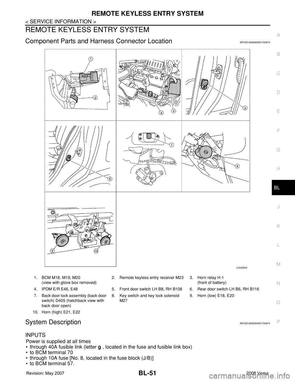
Component Parts and Harness Connector LocationINFOID:0000000001703973
System DescriptionINFOID:0000000001703974
INPUTS
Power is supplied at all times
• through 40A fusible link (letter g , located in the fuse and fusible link box)
• to BCM terminal 70
• through 10A fuse [No. 8, located in the fuse block (J/B)]
• to BCM terminal 57.
LIIA2594E
1. BCM M18, M19, M20
(view with glove box removed)2. Remote keyless entry receiver M23 3. Horn relay H-1
(front of battery)
4. IPDM E/R E46, E48 5. Front door switch LH B8, RH B108 6. Rear door switch LH B6, RH B116
7. Back door lock assembly (back door
switch) D405 (hatchback view with
back door open)8. Key switch and key lock solenoid
M279. Horn (low) E18, E20
10. Horn (high) E21, E22
Page 696 of 2771

BL-262
< SERVICE INFORMATION >
BODY REPAIR
1. When repairing and painting a portion of the body adjacent to plastic parts, consider their characteristics
(influence of heat and solvent) and remove them if necessary or take suitable measures to protect them.
2. Plastic parts should be repaired and painted using methods suiting the materials
, characteristics.
LOCATION OF PLASTIC PARTS
Abbre-
viationMaterial nameHeat resisting
temperature
°C (°F)Resistance to gasoline and
solventsOther cautions
PE Polyethylene 60 (140)Gasoline and most solvents are
harmless if applied for a very
short time (wipe up quickly).Flammable
PVC Polyvinyl Chloride 80 (176) Same as above.Poison gas is emitted
when burned.
EPM/
EPDMEthylene Propylene (Diene) rub-
ber80 (176) Same as above. Flammable
TPO/
TPRThermoplastic Olefine/
Thermoplastic Rubber80 (176) Same as above. Flammable
PP Polypropylene 90 (194) Same as above.Flammable, avoid bat-
tery acid.
UP Polyester thermoset 90 (194) Same as above. Flammable
PS Polystyrene 80 (176) Avoid solvents. Flammable
ABSAcrylonitrile Butadiene Styrene
resin80 (176) Avoid gasoline and solvents.
AES Acrylonitrile Ethylene Styrene 80 (176) Same as above.
PMMA Polymethyl Methacrylate 85 (185) Same as above.
AAS Acrylonitrile Acrylic Styrene 85 (185) Same as above.
AS Acrylonitrile Styrene 85 (185) Same as above.
EVA Polyvinyl Ethyl Acetate 90 (194) Same as above.
ASA Acrylonitrile Styrene Acrylate 100 (222) Same as above. Flammable
PPO/
PPEPolyphenylene Oxide/
Polyphenylene Ether110 (230) Same as above.
PC Polycarbonate 120 (248) Same as above.
PAR Polyacrylate 180 (356) Same as above.
L-
LDPELenear Low Density PE 45 (100)Gasoline and most solvents are
harmless.Flammable
PUR Polyurethane 90 (194) Same as above.
TPU Thermoplastic Urethane 110 (230) Same as above.
PPC Polypropylene Composite 115 (239) Same as above. Flammable
POM Polyacetal 120 (248) Same as above. Avoid battery acid.
PBT+P
CPolybutylene Terephtha-
late+Polycarbonate120 (248) Same as above. Flammable
PA Polyamide (Nylon) 140 (284) Same as above.Avoid immersing in wa-
ter.
PBT Polybutylene Terephthalate 140 (284) Same as above.
FRP Fiber Reinforced Plastics 170 (338) Same as above. Avoid battery acid.
PET Polyethylene Terephthalate 180 (356) Same as above.
PEI Polyetherimide 200 (392) Same as above.
Page 840 of 2771
CVT-1
TRANSMISSION/TRANSAXLE
D
E
F
G
H
I
J
K
L
M
SECTION CVT
A
B
CVT
N
O
P
CONTENTS
CVT
SERVICE INFORMATION ............................5
INDEX FOR DTC .................................................5
Alphabetical Index .....................................................5
DTC No. Index ..........................................................5
PRECAUTIONS ...................................................7
Precaution for Supplemental Restraint System
(SRS) "AIR BAG" and "SEAT BELT PRE-TEN-
SIONER" ...................................................................
7
Precaution Necessary for Steering Wheel Rota-
tion After Battery Disconnect .....................................
7
Precaution for On Board Diagnosis (OBD) System
of CVT and Engine ....................................................
7
Service After Replacing TCM and Transaxle As-
sembly .......................................................................
8
Removal and Installation Procedure for CVT Unit
Connector ..................................................................
9
Precaution ...............................................................10
Service Notice or Precaution ...................................11
PREPARATION ..................................................12
Special Service Tool ...............................................12
Commercial Service Tool ........................................12
CVT FLUID .........................................................13
Checking CVT Fluid ................................................13
Changing CVT Fluid ................................................14
CVT Fluid Cooler Cleaning .....................................14
CVT SYSTEM .....................................................18
Cross-Sectional View - RE0F08A ...........................18
Control System ........................................................19
Hydraulic Control System ........................................20
TCM Function ..........................................................20
CAN Communication ...............................................21
Input/Output Signal of TCM .....................................22
Line Pressure and Secondary Pressure Control .....22
Shift Control ............................................................23
Lock-up and Select Control .....................................24
Control Valve ...........................................................25
ON BOARD DIAGNOSTIC (OBD) SYSTEM ....26
Introduction ..............................................................26
OBD-II Function for CVT System ............................26
One or Two Trip Detection Logic of OBD-II .............26
OBD-II Diagnostic Trouble Code (DTC) ..................26
Malfunction Indicator Lamp (MIL) ............................27
TROUBLE DIAGNOSIS ....................................29
DTC Inspection Priority Chart ..................................29
Fail-Safe ..................................................................29
How to Perform Trouble Diagnosis for Quick and
Accurate Repair .......................................................
30
CVT Electrical Parts Location ..................................35
Circuit Diagram ........................................................36
Inspections before Trouble Diagnosis .....................36
Road Test ................................................................40
Check before Engine Is Started ...............................41
Check at Idle ............................................................41
Cruise Test ..............................................................43
Vehicle Speed When Shifting Gears .......................45
TCM Terminal and Reference Value .......................45
CONSULT-III Function (TRANSMISSION) ..............47
Diagnosis Procedure without CONSULT-III ............55
DTC U1000 CAN COMMUNICATION LINE .....56
Description ...............................................................56
On Board Diagnosis Logic .......................................56
Possible Cause ........................................................56
DTC Confirmation Procedure ..................................56
Wiring Diagram - CVT - CAN ...................................57
Diagnosis Procedure ...............................................58
DTC U1010 TRANSMISSION CONTROL
MODULE (CAN) ................................................
59
Description ...............................................................59
On Board Diagnosis Logic .......................................59
Possible Cause ........................................................59
DTC Confirmation Procedure ..................................59
Diagnosis Procedure ...............................................59
DTC P0615 START SIGNAL CIRCUIT .............60
Page 1854 of 2771
PRECAUTIONS
GI-3
< SERVICE INFORMATION >
C
D
E
F
G
H
I
J
K
L
MB
GI
N
O
P
General PrecautionINFOID:0000000001702424
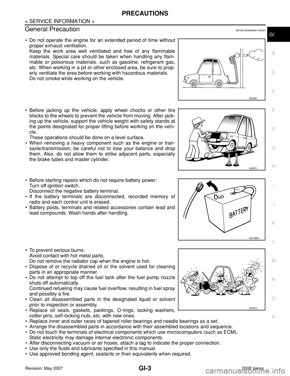
• Do not operate the engine for an extended period of time without
proper exhaust ventilation.
Keep the work area well ventilated and free of any flammable
materials. Special care should be taken when handling any flam-
mable or poisonous materials, such as gasoline, refrigerant gas,
etc. When working in a pit or other enclosed area, be sure to prop-
erly ventilate the area before working with hazardous materials.
Do not smoke while working on the vehicle.
• Before jacking up the vehicle, apply wheel chocks or other tire
blocks to the wheels to prevent the vehicle from moving. After jack-
ing up the vehicle, support the vehicle weight with safety stands at
the points designated for proper lifting before working on the vehi-
cle.
These operations should be done on a level surface.
• When removing a heavy component such as the engine or tran-
saxle/transmission, be careful not to lose your balance and drop
them. Also, do not allow them to strike adjacent parts, especially
the brake tubes and master cylinder.
• Before starting repairs which do not require battery power:
Turn off ignition switch.
Disconnect the negative battery terminal.
• If the battery terminals are disconnected, recorded memory of
radio and each control unit is erased.
• Battery posts, terminals and related accessories contain lead and
lead compounds. Wash hands after handling.
• To prevent serious burns:
Avoid contact with hot metal parts.
Do not remove the radiator cap when the engine is hot.
• Dispose of or recycle drained oil or the solvent used for cleaning
parts in an appropriate manner.
• Do not attempt to top off the fuel tank after the fuel pump nozzle
shuts off automatically.
Continued refueling may cause fuel overflow, resulting in fuel spray
and possibly a fire.
• Clean all disassembled parts in the designated liquid or solvent
prior to inspection or assembly.
• Replace oil seals, gaskets, packings, O-rings, locking washers,
cotter pins, self-locking nuts, etc. with new ones.
• Replace inner and outer races of tapered roller bearings and needle bearings as a set.
• Arrange the disassembled parts in accordance with their assembled locations and sequence.
• Do not touch the terminals of electrical components which use microcomputers (such as ECM).
Static electricity may damage internal electronic components.
• After disconnecting vacuum or air hoses, attach a tag to indicate the proper connection.
• Use only the fluids and lubricants specified in this manual.
• Use approved bonding agent, sealants or their equivalents when required.
SGI285
SGI231
SEF289H
SGI233
Page 1861 of 2771
GI-10
< SERVICE INFORMATION >
HOW TO USE THIS MANUAL
3.Refer to Component Parts and Harness Connector Location for the Systems described in each
section for identification/location of components and harness connectors.
4.Refer to the Circuit Diagram for quick pinpoint check.
If you need to check circuit continuity between harness connectors in more detail, such as when a
sub-harness is used, refer to Wiring Diagram in each individual section and Harness Layout in PG
section for identification of harness connectors.
5.When checking circuit continuity, ignition switch should be OFF.
6.Before checking voltage at connectors, check battery voltage.
7.After accomplishing the Diagnostic Procedures and Electrical Components Inspection, make sure
that all harness connectors are reconnected as they were.
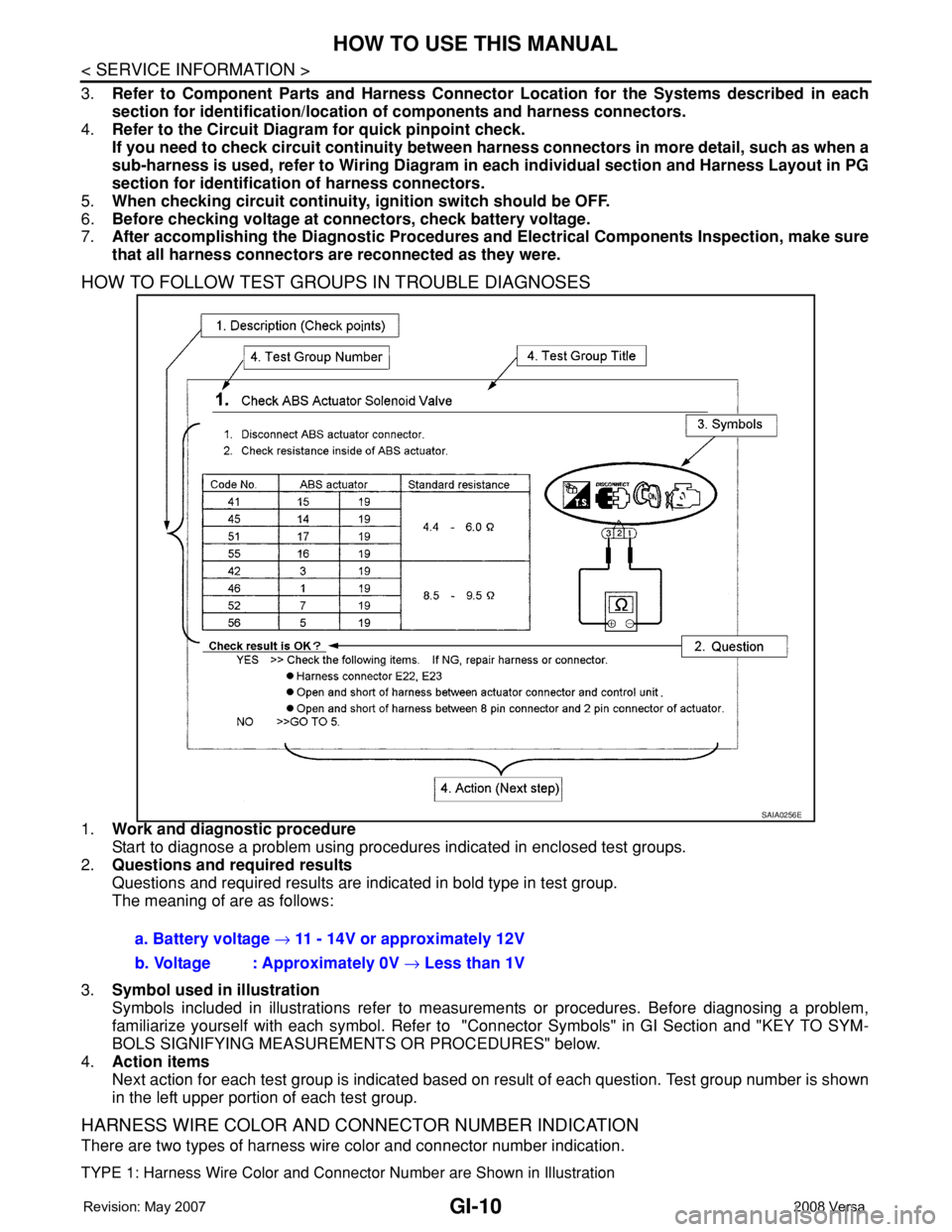
HOW TO FOLLOW TEST GROUPS IN TROUBLE DIAGNOSES
1.Work and diagnostic procedure
Start to diagnose a problem using procedures indicated in enclosed test groups.
2.Questions and required results
Questions and required results are indicated in bold type in test group.
The meaning of are as follows:
3.Symbol used in illustration
Symbols included in illustrations refer to measurements or procedures. Before diagnosing a problem,
familiarize yourself with each symbol. Refer to "Connector Symbols" in GI Section and "KEY TO SYM-
BOLS SIGNIFYING MEASUREMENTS OR PROCEDURES" below.
4.Action items
Next action for each test group is indicated based on result of each question. Test group number is shown
in the left upper portion of each test group.
HARNESS WIRE COLOR AND CONNECTOR NUMBER INDICATION
There are two types of harness wire color and connector number indication.
TYPE 1: Harness Wire Color and Connector Number are Shown in Illustration
SAIA0256E
a. Battery voltage → 11 - 14V or approximately 12V
b. Voltage : Approximately 0V → Less than 1V
Page 1867 of 2771
GI-16
< SERVICE INFORMATION >
HOW TO USE THIS MANUAL
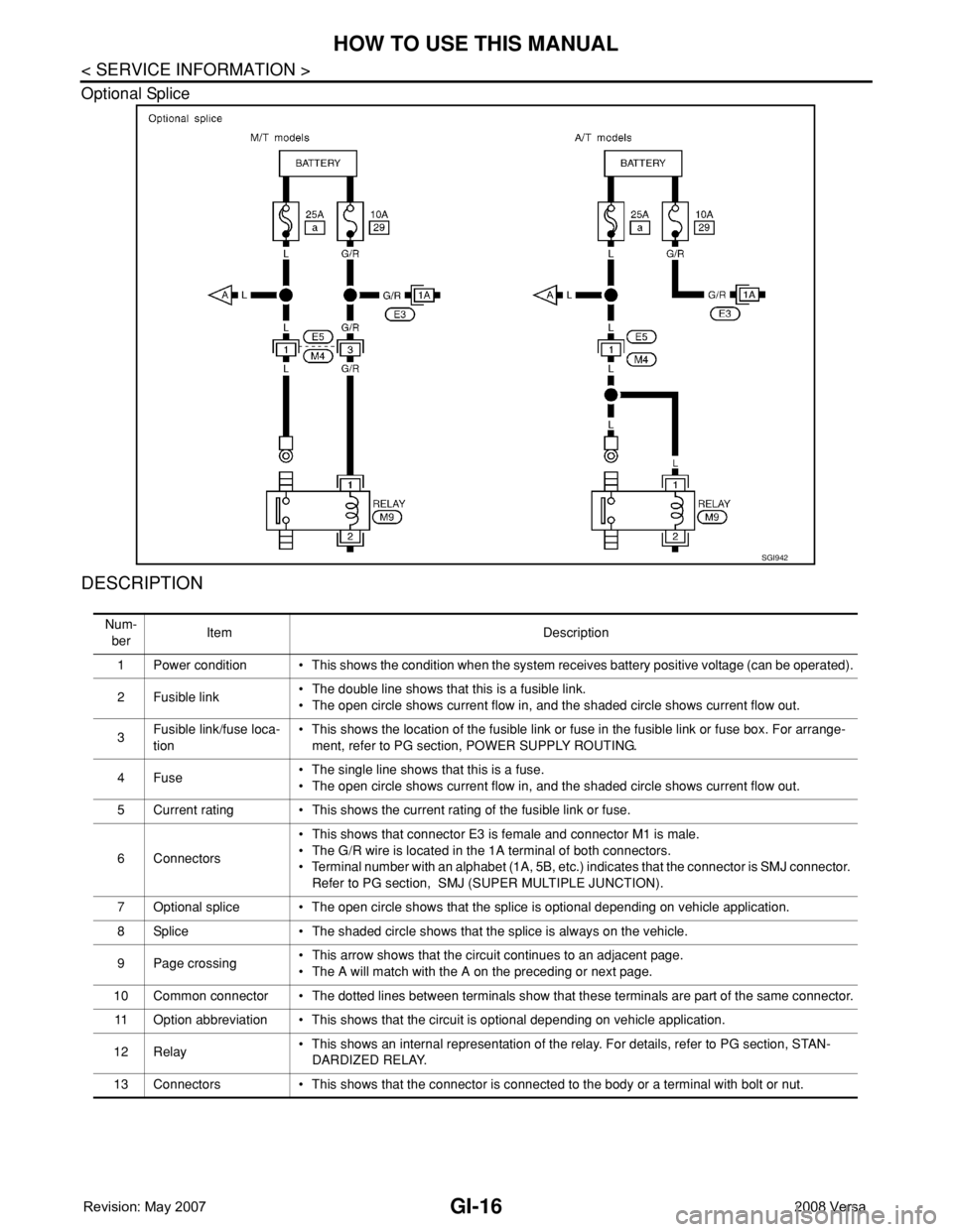
Optional Splice
DESCRIPTION
SGI942
Num-
berItem Description
1 Power condition • This shows the condition when the system receives battery positive voltage (can be operated).
2Fusible link• The double line shows that this is a fusible link.
• The open circle shows current flow in, and the shaded circle shows current flow out.
3Fusible link/fuse loca-
tion• This shows the location of the fusible link or fuse in the fusible link or fuse box. For arrange-
ment, refer to PG section, POWER SUPPLY ROUTING.
4Fuse• The single line shows that this is a fuse.
• The open circle shows current flow in, and the shaded circle shows current flow out.
5 Current rating • This shows the current rating of the fusible link or fuse.
6 Connectors• This shows that connector E3 is female and connector M1 is male.
• The G/R wire is located in the 1A terminal of both connectors.
• Terminal number with an alphabet (1A, 5B, etc.) indicates that the connector is SMJ connector.
Refer to PG section, SMJ (SUPER MULTIPLE JUNCTION).
7 Optional splice • The open circle shows that the splice is optional depending on vehicle application.
8 Splice • The shaded circle shows that the splice is always on the vehicle.
9 Page crossing• This arrow shows that the circuit continues to an adjacent page.
• The A will match with the A on the preceding or next page.
10 Common connector • The dotted lines between terminals show that these terminals are part of the same connector.
11 Option abbreviation • This shows that the circuit is optional depending on vehicle application.
12 Relay• This shows an internal representation of the relay. For details, refer to PG section, STAN-
DARDIZED RELAY.
13 Connectors • This shows that the connector is connected to the body or a terminal with bolt or nut.