2008 NISSAN LATIO ignition
[x] Cancel search: ignitionPage 19 of 2771

PRECAUTIONS
AT-7
< SERVICE INFORMATION >
D
E
F
G
H
I
J
K
L
MA
B
AT
N
O
P
PRECAUTIONS
Precaution for Supplemental Restraint System (SRS) "AIR BAG" and "SEAT BELT
PRE-TENSIONER"
INFOID:0000000001703151
The Supplemental Restraint System such as “AIR BAG” and “SEAT BELT PRE-TENSIONER”, used along
with a front seat belt, helps to reduce the risk or severity of injury to the driver and front passenger for certain
types of collision. This system includes seat belt switch inputs and dual stage front air bag modules. The SRS
system uses the seat belt switches to determine the front air bag deployment, and may only deploy one front
air bag, depending on the severity of a collision and whether the front occupants are belted or unbelted.
Information necessary to service the system safely is included in the SRS and SB section of this Service Man-
ual.
WARNING:
• To avoid rendering the SRS inoperative, which could increase the risk of personal injury or death in
the event of a collision which would result in air bag inflation, all maintenance must be performed by
an authorized NISSAN/INFINITI dealer.
• Improper maintenance, including incorrect removal and installation of the SRS, can lead to personal
injury caused by unintentional activation of the system. For removal of Spiral Cable and Air Bag
Module, see the SRS section.
• Do not use electrical test equipment on any circuit related to the SRS unless instructed to in this
Service Manual. SRS wiring harnesses can be identified by yellow and/or orange harnesses or har-
ness connectors.
Precaution Necessary for Steering Wheel Rotation After Battery Disconnect
INFOID:0000000001703152
NOTE:
• This Procedure is applied only to models with Intelligent Key system and NVIS/IVIS (NISSAN/INFINITI
VEHICLE IMMOBILIZER SYSTEM - NATS).
• Remove and install all control units after disconnecting both battery cables with the ignition knob in the
″LOCK″ position.
• Always use CONSULT-III to perform self-diagnosis as a part of each function inspection after finishing work.
If DTC is detected, perform trouble diagnosis according to self-diagnostic results.
For models equipped with the Intelligent Key system and NVIS/IVIS, an electrically controlled steering lock
mechanism is adopted on the key cylinder.
For this reason, if the battery is disconnected or if the battery is discharged, the steering wheel will lock and
steering wheel rotation will become impossible.
If steering wheel rotation is required when battery power is interrupted, follow the procedure below before
starting the repair operation.
OPERATION PROCEDURE
1. Connect both battery cables.
NOTE:
Supply power using jumper cables if battery is discharged.
2. Use the Intelligent Key or mechanical key to turn the ignition switch to the ″ACC″ position. At this time, the
steering lock will be released.
3. Disconnect both battery cables. The steering lock will remain released and the steering wheel can be
rotated.
4. Perform the necessary repair operation.
5. When the repair work is completed, return the ignition switch to the ″LOCK″ position before connecting
the battery cables. (At this time, the steering lock mechanism will engage.)
6. Perform a self-diagnosis check of all control units using CONSULT-III.
Precaution for On Board Diagnosis (OBD) System of A/T and EngineINFOID:0000000001703153
The ECM has an on board diagnostic system. It will light up the malfunction indicator lamp (MIL) to warn the
driver of a malfunction causing emission deterioration.
CAUTION:
Page 20 of 2771

AT-8
< SERVICE INFORMATION >
PRECAUTIONS
• Be sure to turn the ignition switch OFF and disconnect battery negative cable from battery negative
terminal before any repair or inspection work. The open/short circuit of related switches, sensors,
solenoid valves, etc. will cause the MIL to light up.
• Be sure to connect and lock the connectors securely after work. A loose (unlocked) connector will
cause the MIL to light up due to an open circuit. (Be sure the connectors are free from water, grease,
dirt, bent terminals, etc.)
• Be sure to route and secure the harnesses properly after work. Interference of the harness with a
bracket, etc. may cause the MIL to light up due to a short circuit.
• Be sure to erase the unnecessary malfunction information (repairs completed) from the TCM and
ECM before returning the vehicle to the customer.
PrecautionINFOID:0000000001703154
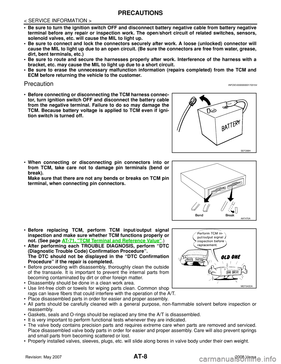
•Before connecting or disconnecting the TCM harness connec-
tor, turn ignition switch OFF and disconnect the battery cable
from the negative terminal. Failure to do so may damage the
TCM. Because battery voltage is applied to TCM even if igni-
tion switch is turned off.
•When connecting or disconnecting pin connectors into or
from TCM, take care not to damage pin terminals (bend or
break).
Make sure that there are not any bends or breaks on TCM pin
terminal, when connecting pin connectors.
•Before replacing TCM, perform TCM input/output signal
inspection and make sure whether TCM functions properly or
not. (See page AT-71, "
TCM Terminal and Reference Value".)
•After performing each TROUBLE DIAGNOSIS, perform “DTC
(Diagnostic Trouble Code) Confirmation Procedure”.
The DTC should not be displayed in the “DTC Confirmation
Procedure” if the repair is completed.
• Before proceeding with disassembly, thoroughly clean the outside
of the transaxle. It is important to prevent the internal parts from
becoming contaminated by dirt or other foreign matter.
• Disassembly should be done in a clean work area.
• Use lint-free cloth or towels for wiping parts clean. Common shop
rags can leave fibers that could interfere with the operation of the A/T.
• Place disassembled parts in order for easier and proper assembly.
• All parts should be carefully cleaned with a general purpose, non-flammable solvent before inspection or
reassembly.
• Gaskets, seals and O-rings should be replaced any time the A/T is disassembled.
• It is very important to perform functional tests whenever they are indicated.
• The valve body contains precision parts and requires extreme care when parts are removed and serviced.
Place disassembled valve body parts in order for easier and proper assembly. Care will also prevent springs
and small parts from becoming scattered or lost.
• Properly installed valves, sleeves, plugs, etc. will slide along bores in valve body under their own weight.
SEF289H
AAT470A
MEF040DA
Page 49 of 2771

ON BOARD DIAGNOSTIC (OBD) SYSTEM
AT-37
< SERVICE INFORMATION >
D
E
F
G
H
I
J
K
L
MA
B
AT
N
O
P
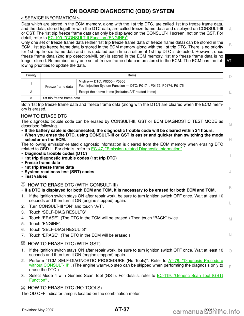
Data which are stored in the ECM memory, along with the 1st trip DTC, are called 1st trip freeze frame data,
and the data, stored together with the DTC data, are called freeze frame data and displayed on CONSULT-III
or GST. The 1st trip freeze frame data can only be displayed on the CONSULT-III screen, not on the GST. For
detail, refer to EC-109, "
CONSULT-II Function (ENGINE)" .
Only one set of freeze frame data (either 1st trip freeze frame data of freeze frame data) can be stored in the
ECM. 1st trip freeze frame data is stored in the ECM memory along with the 1st trip DTC. There is no priority
for 1st trip freeze frame data and it is updated each time a different 1st trip DTC is detected. However, once
freeze frame data (2nd trip detection/MIL on) is stored in the ECM memory, 1st trip freeze frame data is no
longer stored. Remember, only one set of freeze frame data can be stored in the ECM. The ECM has the fol-
lowing priorities to update the data.
Both 1st trip freeze frame data and freeze frame data (along with the DTC) are cleared when the ECM mem-
ory is erased.
HOW TO ERASE DTC
The diagnostic trouble code can be erased by CONSULT-III, GST or ECM DIAGNOSTIC TEST MODE as
described following.
•If the battery cable is disconnected, the diagnostic trouble code will be cleared within 24 hours.
•When you erase the DTC, using CONSULT-III or GST is easier and quicker than switching the mode
selector on the ECM.
The following emission-related diagnostic information is cleared from the ECM memory when erasing DTC
related to OBD-II. For details, refer to EC-47, "
Emission-related Diagnostic Information" .
•Diagnostic trouble codes (DTC)
•1st trip diagnostic trouble codes (1st trip DTC)
•Freeze frame data
•1st trip freeze frame data
•System readiness test (SRT) codes
•Test values
HOW TO ERASE DTC (WITH CONSULT-III)
•If a DTC is displayed for both ECM and TCM, it is necessary to be erased for both ECM and TCM.
1. If the ignition switch stays ON after repair work, be sure to turn ignition switch OFF once. Wait at least 10
seconds and then turn it ON (engine stopped) again.
2. Turn CONSULT-III “ON” and touch “A/T”.
3. Touch “SELF-DIAG RESULTS”.
4. Touch “ERASE”. (The DTC in the TCM will be erased.) Then touch “BACK” twice.
5. Touch “ENGINE”.
6. Touch “SELF-DIAG RESULTS”.
7. Touch “ERASE”. (The DTC in the ECM will be erased.)
HOW TO ERASE DTC (WITH GST)
1. If the ignition switch stays ON after repair work, be sure to turn ignition switch OFF once. Wait at least 10
seconds and then turn it ON (engine stopped) again.
2. Perform “TCM SELF-DIAGNOSTIC PROCEDURE (No Tools)”. Refer to AT-78, "
Diagnosis Procedure
without CONSULT-III" . (The engine warm-up step can be skipped when performing the diagnosis only to
erase the DTC.)
3. Select Mode 4 with Generic Scan Tool (GST). For details, refer to EC-119, "
Generic Scan Tool (GST)
Function" .
HOW TO ERASE DTC (NO TOOLS)
The OD OFF indicator lamp is located on the combination meter.
Priority Items
1
Freeze frame dataMisfire — DTC: P0300 - P0306
Fuel Injection System Function — DTC: P0171, P0172, P0174, P0175
2 Except the above items (Includes A/T related items)
3 1st trip freeze frame data
Page 50 of 2771

AT-38
< SERVICE INFORMATION >
ON BOARD DIAGNOSTIC (OBD) SYSTEM
1. If the ignition switch stays ON after repair work, be sure to turn ignition switch OFF once. Wait at least 10
seconds and then turn it ON (engine stopped) again.
2. Perform “TCM SELF-DIAGNOSTIC PROCEDURE (No Tools)”. Refer to AT-78, "
Diagnosis Procedure
without CONSULT-III" . (The engine warm-up step can be skipped when performing the diagnosis only to
erase the DTC.)
3. Perform “OBD-II SELF-DIAGNOSTIC PROCEDURE (No tools)”. Refer to EC-47, "
Emission-related Diag-
nostic Information" .
Malfunction Indicator Lamp (MIL)INFOID:0000000001703176
DESCRIPTION
The MIL is located on the instrument panel.
1. The MIL will light up when the ignition switch is turned ON with-
out the engine running. This is a bulb check.
• If the MIL does not light up, refer to DI-21
, or see EC-546 .
2. When the engine is started, the MIL should go off.
• If the MIL remains on, the on board diagnostic system has
detected an engine system malfunction.
SEF217U
Page 65 of 2771

TROUBLE DIAGNOSIS
AT-53
< SERVICE INFORMATION >
D
E
F
G
H
I
J
K
L
MA
B
AT
N
O
P
• Before road test, familiarize yourself with all test procedures and
items to check.
• Perform tests on all items until specified symptom is found. Trou-
bleshoot the items which are checked out to be no good after road
test. Refer to AT-73, "
CONSULT-III Function (A/T)" , AT-78, "Diag-
nosis Procedure without CONSULT-III" and AT-173 .
Check Before Engine Is StartedINFOID:0000000001703184
1.CHECK OD OFF INDICATOR LAMP
1. Park vehicle on flat surface.
2. Move selector lever to “P” position.
3. Turn ignition switch OFF. Wait at least 5 seconds.
4. Turn ignition switch ON. (Do not start engine.)
Does OD OFF indicator lamp come on for about 2 seconds?
YES >> 1. Turn ignition switch OFF.
2. Perform self-diagnosis and note NG items.
Refer to AT-73, "
CONSULT-III Function (A/T)" , AT-
78, "Diagnosis Procedure without CONSULT-III" .
3. Go to AT-53, "
Check at Idle" .
NO >> Stop “Road Test”. Go to AT-176, "
OD OFF Indicator
Lamp Does Not Come On" .
Check at IdleINFOID:0000000001703185
1.CHECK ENGINE START
1. Park vehicle on flat surface.
2. Turn ignition switch ON. (Do not start engine.)
3. Move selector lever to “P” or “N” position.
4. Turn ignition switch to “START” position.
Is engine started?
YES >> GO TO 2.
NO >> • Stop “Road Test”. Mark the box on the AT-40, "
How to
Perform Trouble Diagnosis for Quick and Accurate
Repair" .
•Go to AT-178, "
Engine Cannot Be Started in "P" and
"N" Position" .
2.CHECK ENGINE START
1. Turn ignition switch ON. (Do not start engine.)
SAT496G
SAT772B
SCIA7140E
SAT769B
Page 66 of 2771

AT-54
< SERVICE INFORMATION >
TROUBLE DIAGNOSIS
2. Move selector lever to “R”, “D”, “2” or “1” position.
3. Turn ignition switch to “START” position.
Is engine started?
YES >> • Stop “Road Test”. Mark the box on the AT-40, "How to
Perform Trouble Diagnosis for Quick and Accurate
Repair" .
•Go to AT-178, "
Engine Cannot Be Started in "P" and
"N" Position" .
• Continue “Road Test”.
NO >> GO TO 3.
3.CHECK VEHICLE MOVE
1. Move selector lever to “P” position.
2. Turn ignition switch OFF.
3. Release parking brake.
4. Push vehicle forward or backward.
Does vehicle move when it is pushed forward or backyard?
YES >> • Mark the box on the AT-40, "How to Perform Trouble
Diagnosis for Quick and Accurate Repair" .
•Go to AT-179, "
In "P" Position, Vehicle Moves Forward
or Backward When Pushed" .
• Continue “Road Test”.
NO >> GO TO 4.
4.CHECK VEHICLE MOVE
1. Apply parking brake.
2. Start engine.
3. Move selector lever to “N” position.
4. Release parking brake.
Does vehicle move forward or backward?
YES >> • Mark the box on the AT-40, "How to Perform Trouble
Diagnosis for Quick and Accurate Repair" .
•Go to AT-179, "
In "N" Position, Vehicle Moves" .
• Continue “Road Test”.
NO >> GO TO 5.
5.CHECK SHIFT SHOCK
SAT770B
SAT768B
SAT796A
SAT771B
Page 80 of 2771

AT-68
< SERVICE INFORMATION >
TROUBLE DIAGNOSIS
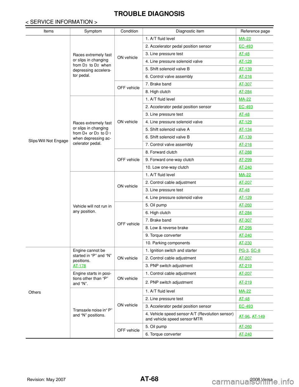
Slips/Will Not EngageRaces extremely fast
or slips in changing
from D
3 to D2 when
depressing accelera-
tor pedal. ON vehicle1. A/T fluid levelMA-22
2. Accelerator pedal position sensor EC-493
3. Line pressure testAT- 4 8
4. Line pressure solenoid valveAT- 1 2 9
5. Shift solenoid valve BAT- 1 3 9
6. Control valve assemblyAT- 2 1 6
OFF vehicle7. Brake bandAT- 3 0 78. High clutchAT- 2 8 4
Races extremely fast
or slips in changing
from D
4 or D3 to D 1
when depressing ac-
celerator pedal.ON vehicle1. A/T fluid levelMA-22
2. Accelerator pedal position sensorEC-493
3. Line pressure testAT- 4 8
4. Line pressure solenoid valveAT- 1 2 9
5. Shift solenoid valve AAT- 1 3 4
6. Shift solenoid valve BAT- 1 3 9
7. Control valve assemblyAT- 2 1 6
OFF vehicle8. Forward clutchAT- 2 8 89. Forward one-way clutchAT- 2 9 9
10. Low one-way clutchAT- 2 4 0
Vehicle will not run in
any position.ON vehicle1. A/T fluid levelMA-22
2. Control cable adjustmentAT- 2 0 7
3. Line pressure testAT- 4 8
4. Line pressure solenoid valveAT- 1 2 9
OFF vehicle5. Oil pumpAT- 2 6 0
6. High clutchAT- 2 8 4
7. Brake bandAT- 3 0 7
8. Low & reverse brakeAT- 2 9 5
9. Torque converterAT- 2 4 0
10. Parking componentsAT- 2 3 0
OthersEngine cannot be
started in “P” and “N”
positions.
AT- 1 7 8
ON vehicle1. Ignition switch and starterPG-3
, SC-8
2. Control cable adjustmentAT- 2 0 7
3. PNP switch adjustmentAT- 2 1 9
Engine starts in posi-
tions other than “P”
and “N”.ON vehicle1. Control cable adjustmentAT- 2 0 7
2. PNP switch adjustmentAT- 2 1 9
Transaxle noise in“ P”
and “N” positions.ON vehicle1. A/T fluid levelMA-22
2. Line pressure testAT- 4 8
3. Accelerator pedal position sensorEC-493
4. Vehicle speed sensor·A/T (Revolution sensor)
and vehicle speed sensor·MTRAT- 9 6, AT- 1 4 9
OFF vehicle5. Oil pumpAT- 2 6 06. Torque converterAT- 2 4 0
Items Symptom Condition Diagnostic item Reference page
Page 83 of 2771

TROUBLE DIAGNOSIS
AT-71
< SERVICE INFORMATION >
D
E
F
G
H
I
J
K
L
MA
B
AT
N
O
P
TCM Terminal and Reference ValueINFOID:0000000001703192
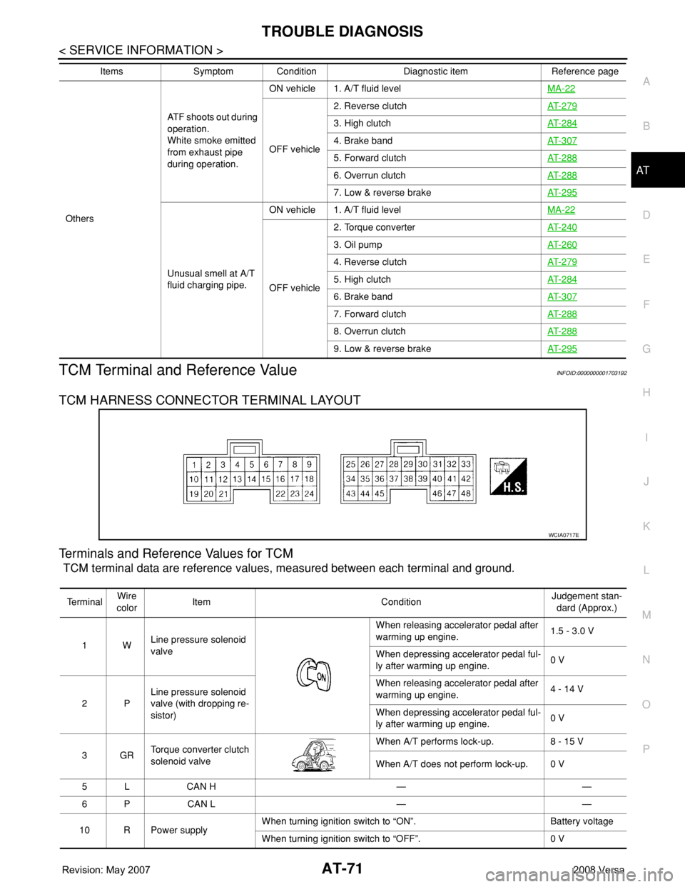
TCM HARNESS CONNECTOR TERMINAL LAYOUT
Terminals and Reference Values for TCM
TCM terminal data are reference values, measured between each terminal and ground.
OthersATF shoots out during
operation.
White smoke emitted
from exhaust pipe
during operation.ON vehicle 1. A/T fluid levelMA-22
OFF vehicle2. Reverse clutchAT- 2 7 9
3. High clutchAT- 2 8 4
4. Brake bandAT- 3 0 7
5. Forward clutchAT- 2 8 8
6. Overrun clutchAT- 2 8 8
7. Low & reverse brakeAT- 2 9 5
Unusual smell at A/T
fluid charging pipe.ON vehicle 1. A/T fluid levelMA-22
OFF vehicle2. Torque converterAT- 2 4 0
3. Oil pumpAT- 2 6 0
4. Reverse clutchAT- 2 7 9
5. High clutchAT- 2 8 4
6. Brake bandAT- 3 0 7
7. Forward clutchAT- 2 8 8
8. Overrun clutchAT- 2 8 8
9. Low & reverse brakeAT- 2 9 5
Items Symptom Condition Diagnostic item Reference page
WCIA0717E
Te r m i n a lWire
colorItem ConditionJudgement stan-
dard (Approx.)
1WLine pressure solenoid
valveWhen releasing accelerator pedal after
warming up engine.1.5 - 3.0 V
When depressing accelerator pedal ful-
ly after warming up engine.0 V
2PLine pressure solenoid
valve (with dropping re-
sistor)When releasing accelerator pedal after
warming up engine.4 - 14 V
When depressing accelerator pedal ful-
ly after warming up engine.0 V
3GRTorque converter clutch
solenoid valveWhen A/T performs lock-up. 8 - 15 V
When A/T does not perform lock-up. 0 V
5 L CAN H — —
6 P CAN L — —
10 R Power supplyWhen turning ignition switch to “ON”. Battery voltage
When turning ignition switch to “OFF”. 0 V