2008 NISSAN LATIO Wiring diagram ckp sensor
[x] Cancel search: Wiring diagram ckp sensorPage 1078 of 2771

EC-4
Diagnosis Procedure .............................................260
DTC P0172 FUEL INJECTION SYSTEM
FUNCTION .......................................................
264
On Board Diagnosis Logic .....................................264
DTC Confirmation Procedure ................................264
Wiring Diagram ......................................................266
Diagnosis Procedure .............................................267
DTC P0181 FTT SENSOR ...............................270
Component Description .........................................270
On Board Diagnosis Logic .....................................270
DTC Confirmation Procedure ................................270
Wiring Diagram ......................................................271
Diagnosis Procedure .............................................271
Component Inspection ...........................................273
Removal and Installation .......................................273
DTC P0182, P0183 FTT SENSOR ..................274
Component Description .........................................274
On Board Diagnosis Logic .....................................274
DTC Confirmation Procedure ................................274
Wiring Diagram ......................................................275
Diagnosis Procedure .............................................275
Component Inspection ...........................................277
Removal and Installation .......................................277
DTC P0222, P0223 TP SENSOR ....................278
Component Description .........................................278
CONSULT-II Reference Value in Data Monitor
Mode ......................................................................
278
On Board Diagnosis Logic .....................................278
DTC Confirmation Procedure ................................278
Wiring Diagram ......................................................280
Diagnosis Procedure .............................................281
Component Inspection ...........................................283
Removal and Installation .......................................283
DTC P0300 - P0304 MULTIPLE CYLINDER
MISFIRE, NO. 1 - 4 CYLINDER MISFIRE .......
284
On Board Diagnosis Logic .....................................284
DTC Confirmation Procedure ................................284
Diagnosis Procedure .............................................285
DTC P0327, P0328 KS ....................................291
Component Description .........................................291
On Board Diagnosis Logic .....................................291
DTC Confirmation Procedure ................................291
Wiring Diagram ......................................................292
Diagnosis Procedure .............................................293
Component Inspection ...........................................294
Removal and Installation .......................................294
DTC P0335 CKP SENSOR (POS) ...................295
Component Description .........................................295
CONSULT-II Reference Value in Data Monitor
Mode ......................................................................
295
On Board Diagnosis Logic .....................................295
DTC Confirmation Procedure ................................295
Wiring Diagram ......................................................297
Diagnosis Procedure .............................................298
Component Inspection ..........................................301
Removal and Installation .......................................301
DTC P0340 CMP SENSOR (PHASE) ..............302
Component Description ........................................302
CONSULT-II Reference Value in Data Monitor
Mode .....................................................................
302
On Board Diagnosis Logic ....................................302
DTC Confirmation Procedure ................................302
Wiring Diagram .....................................................304
Diagnosis Procedure .............................................305
Component Inspection ..........................................307
Removal and Installation .......................................307
DTC P0420 THREE WAY CATALYST FUNC-
TION ..................................................................
308
On Board Diagnosis Logic ....................................308
DTC Confirmation Procedure ................................308
Overall Function Check .........................................309
Diagnosis Procedure .............................................310
DTC P0441 EVAP CONTROL SYSTEM ..........313
System Description ...............................................313
On Board Diagnosis Logic ....................................313
DTC Confirmation Procedure ................................313
Overall Function Check .........................................314
Diagnosis Procedure .............................................315
DTC P0442 EVAP CONTROL SYSTEM ..........318
On Board Diagnosis Logic ....................................318
DTC Confirmation Procedure ................................318
Diagnosis Procedure .............................................320
DTC P0443 EVAP CANISTER PURGE VOL-
UME CONTROL SOLENOID VALVE ...............
325
Description ............................................................325
CONSULT-II Reference Value in Data Monitor
Mode .....................................................................
325
On Board Diagnosis Logic ....................................326
DTC Confirmation Procedure ................................326
Wiring Diagram .....................................................327
Diagnosis Procedure .............................................328
Component Inspection ..........................................331
Removal and Installation .......................................331
DTC P0444, P0445 EVAP CANISTER PURGE
VOLUME CONTROL SOLENOID VALVE .......
332
Description ............................................................332
CONSULT-II Reference Value in Data Monitor
Mode .....................................................................
332
On Board Diagnosis Logic ....................................333
DTC Confirmation Procedure ................................333
Wiring Diagram .....................................................334
Diagnosis Procedure .............................................335
Component Inspection ..........................................337
Removal and Installation .......................................337
DTC P0447 EVAP CANISTER VENT CON-
TROL VALVE ...................................................
338
Page 1224 of 2771

EC-150
< SERVICE INFORMATION >
DTC P0011 IVT CONTROL
Are there any service records that may cause timing chain misaligned?
Ye s o r N o
Yes >> Check timing chain installation. Refer to EM-37.
No >> GO TO 7.
7.CHECK LUBRICATION CIRCUIT
Refer to EM-47, "
Removal and Installation".
OK or NG
OK >> GO TO 8.
NG >> Clean lubrication line.
8.CHECK INTERMITTENT INCIDENT
Refer to EC-136
.
For Wiring Diagram, refer to EC-297, "
Wiring Diagram" for CKP sensor (POS) and EC-304, "Wiring Diagram"
for CMP sensor (PHASE).
>>INSPECTION END
Component InspectionINFOID:0000000001702622
INTAKE VALVE TIMING CONTROL SOLENOID VALVE
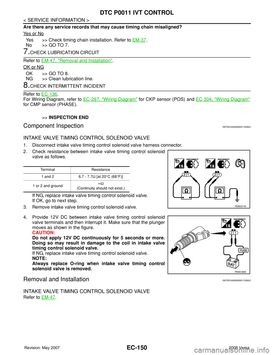
1. Disconnect intake valve timing control solenoid valve harness connector.
2. Check resistance between intake valve timing control solenoid
valve as follows.
If NG, replace intake valve timing control solenoid valve.
If OK, go to next step.
3. Remove intake valve timing control solenoid valve.
4. Provide 12V DC between intake valve timing control solenoid
valve terminals and then interrupt it. Make sure that the plunger
moves as shown in the figure.
CAUTION:
Do not apply 12V DC continuously for 5 seconds or more.
Doing so may result in damage to the coil in intake valve
timing control solenoid valve.
If NG, replace intake valve timing control solenoid valve.
NOTE:
Always replace O-ring when intake valve timing control
solenoid valve is removed.
Removal and InstallationINFOID:0000000001702623
INTAKE VALVE TIMING CONTROL SOLENOID VALVE
Refer to EM-47.
Terminal Resistance
1 and 2 6.7 - 7.7Ω [at 20°C (68°F)]
1 or 2 and ground∞Ω
(Continuity should not exist.)
PBIB0574E
PBIB2388E
Page 1371 of 2771

DTC P0335 CKP SENSOR (POS)
EC-297
< SERVICE INFORMATION >
C
D
E
F
G
H
I
J
K
L
MA
EC
N
P O
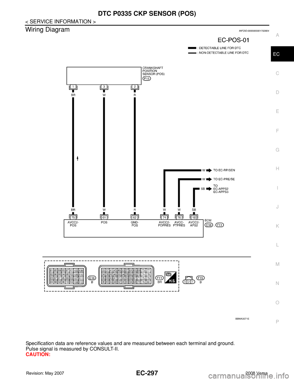
Wiring DiagramINFOID:0000000001702804
Specification data are reference values and are measured between each terminal and ground.
Pulse signal is measured by CONSULT-II.
CAUTION:
BBWA3071E
Page 1373 of 2771

DTC P0335 CKP SENSOR (POS)
EC-299
< SERVICE INFORMATION >
C
D
E
F
G
H
I
J
K
L
MA
EC
N
P O
OK or NG
OK >> GO TO 2.
NG >> Repair or replace ground connections.
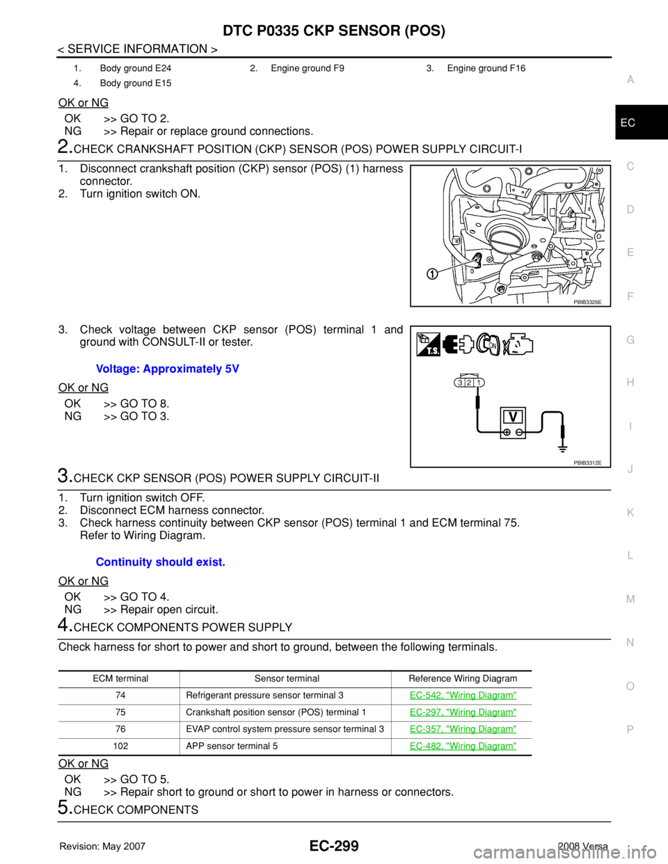
2.CHECK CRANKSHAFT POSITION (CKP) SENSOR (POS) POWER SUPPLY CIRCUIT-I
1. Disconnect crankshaft position (CKP) sensor (POS) (1) harness
connector.
2. Turn ignition switch ON.
3. Check voltage between CKP sensor (POS) terminal 1 and
ground with CONSULT-II or tester.
OK or NG
OK >> GO TO 8.
NG >> GO TO 3.
3.CHECK CKP SENSOR (POS) POWER SUPPLY CIRCUIT-II
1. Turn ignition switch OFF.
2. Disconnect ECM harness connector.
3. Check harness continuity between CKP sensor (POS) terminal 1 and ECM terminal 75.
Refer to Wiring Diagram.
OK or NG
OK >> GO TO 4.
NG >> Repair open circuit.
4.CHECK COMPONENTS POWER SUPPLY
Check harness for short to power and short to ground, between the following terminals.
OK or NG
OK >> GO TO 5.
NG >> Repair short to ground or short to power in harness or connectors.
5.CHECK COMPONENTS
1. Body ground E24 2. Engine ground F9 3. Engine ground F16
4. Body ground E15
PBIB3326E
Voltage: Approximately 5V
PBIB3312E
Continuity should exist.
ECM terminal Sensor terminal Reference Wiring Diagram
74 Refrigerant pressure sensor terminal 3EC-542, "
Wiring Diagram"
75 Crankshaft position sensor (POS) terminal 1EC-297, "Wiring Diagram"
76 EVAP control system pressure sensor terminal 3EC-357, "Wiring Diagram"
102 APP sensor terminal 5EC-482, "Wiring Diagram"
Page 1374 of 2771

EC-300
< SERVICE INFORMATION >
DTC P0335 CKP SENSOR (POS)
Check the following.
• Refrigerant pressure sensor. (Refer to MTC-22
.)
• EVAP control system pressure sensor. (Refer to EC-361, "
Component Inspection".)
OK or NG
OK >> GO TO 6.
NG >> Replace malfunctioning components.
6.CHECK APP SENSOR
Refer to EC-485, "
Component Inspection".
OK or NG
OK >> GO TO 8.
NG >> GO TO 7.
7.REPLACE ACCELERATOR PEDAL ASSEMBLY
1. Replace accelerator pedal assembly.
2. Perform EC-76, "
Accelerator Pedal Released Position Learning".
3. Perform EC-76, "
Throttle Valve Closed Position Learning".
4. Perform EC-76, "
Idle Air Volume Learning".
>>INSPECTION END
8.CHECK CKP SENSOR (POS) GROUND CIRCUIT FOR OPEN AND SHORT
1. Turn ignition switch OFF.
2. Disconnect ECM harness connector.
3. Check harness continuity between CKP sensor (POS) terminal 2 and ECM terminal 62.
Refer to Wiring Diagram.
4. Also check harness for short to ground and short to power.
OK or NG
OK >> GO TO 9.
NG >> Repair open circuit or short to ground or short to power in harness or connectors.
9.CHECK CKP SENSOR (POS) INPUT SIGNAL CIRCUIT FOR OPEN AND SHORT
1. Check harness continuity between CKP sensor (POS) terminal 3 and ECM terminal 61.
Refer to Wiring Diagram.
2. Also check harness for short to ground and short to power.
OK or NG
OK >> GO TO 10.
NG >> Repair open circuit or short to ground or short to power in harness or connectors.
10.CHECK CRANKSHAFT POSITION SENSOR (POS)
Refer to EC-301, "
Component Inspection".
OK or NG
OK >> GO TO 11.
NG >> Replace crankshaft position sensor (POS).
11 .CHECK GEAR TOOTH
Visually check for chipping signal plate gear tooth.
OK or NG
OK >> GO TO 12.
NG >> Replace the signal plate.
12.CHECK INTERMITTENT INCIDENTContinuity should exist.
Continuity should exist.