Page 2314 of 2771
MT-26
< SERVICE INFORMATION >
TRANSAXLE ASSEMBLY
20. Remove differential side oil seals (1) from clutch housing and
transaxle case using suitable tool.
CAUTION:
Be careful not to damage clutch housing and transaxle
case.
21. Remove differential side bearing outer race (1) from clutch hous-
ing using suitable tool.
CAUTION:
Be careful not to damage clutch housing.
22. Remove differential side bearing outer race (1) and shim (2)
from transaxle case using a brass bar as shown.
CAUTION:
Be careful not to damage transaxle case.
23. Remove retaining pin from control lever (1) using suitable tool.
24. Remove control lever.
25. Remove shift finger (1) from transaxle case.
PCIB1704E
PCIB1716E
PCIB1705E
PCIB1711E
PCIB1712E
Page 2319 of 2771
TRANSAXLE ASSEMBLY
MT-31
< SERVICE INFORMATION >
D
E
F
G
H
I
J
K
L
MA
B
MT
N
O
P
9. Install oil gutter (1) onto transaxle case.
10. Install shift lever oil seal (1) and bushing (2) into transaxle case
using suitable tool (A).
11. Install control lever oil seal and bushings into transaxle case
using suitable tool.
12. Install shift finger (1) into transaxle case.
13. Install control lever (1) and then install retaining pin.
CAUTION:
Do not reuse retaining pin.
14. Install shim and differential side bearing outer race into transaxle
case using Tool (A).
PCIB1730E
PCIB1731E
PCIB1712E
PCIB1711E
Tool number : ST33400001 (J-26082)
PCIB1726E
Page 2320 of 2771
MT-32
< SERVICE INFORMATION >
TRANSAXLE ASSEMBLY
15. Install differential side bearing outer race into clutch housing
using Tool (A).
16. Install differential side oil seals (1) into clutch housing and tran-
saxle case using Tool (A).
17. Install magnet onto clutch housing.
18. Install final drive assembly into clutch housing.
19. Install input shaft assembly (1), mainshaft assembly (2) and 1st-
2nd fork rod assembly (3) into clutch housing.
20. Install spring washer located under the reverse idler shaft.
21. Install reverse gear assembly (1) according to the following:
a. Lift up the input shaft assembly (2) and mainshaft assembly (3).
b. Install reverse gear assembly (1) and reverse fork rod (4) to
clutch housing.
22. While lifting up fork rod (1), install 3rd-4th and 5th-6th fork rod
assembly to clutch housing. Tool number : KV38100200 ( — )
PCIB1722E
Tool number : KV38100300 (J-25523)
PCIB1732E
PCIB1702E
PCIB1701E
PCIB1700E
Page 2334 of 2771
MT-46
< SERVICE INFORMATION >
FINAL DRIVE
FINAL DRIVE
Disassembly and AssemblyINFOID:0000000001703146
DISASSEMBLY
1. Remove differential side bearing inner race (clutch housing side)
(1) using Tool (A) and suitable tool.
2. Remove speedometer drive gear.
3. Remove final gear bolts (1), and then separate the final gear (2)
from differential case.
4. Remove differential side bearing inner race (transaxle case
side) (1) using suitable tool (A).
5. Remove lock ring (1) from differential case.
6. Remove pinion mate shaft, pinion mate gears, side gears and
thrust washer from differential case.
INSPECTION AFTER DISASSEMBLY
Gear, Washer, Shaft and Case
Tool number : ST33061000 (J-8107-2)
PCIB1767E
PCIB1766E
PCIB1765E
PCIB1764E
Page 2335 of 2771

FINAL DRIVE
MT-47
< SERVICE INFORMATION >
D
E
F
G
H
I
J
K
L
MA
B
MT
N
O
P
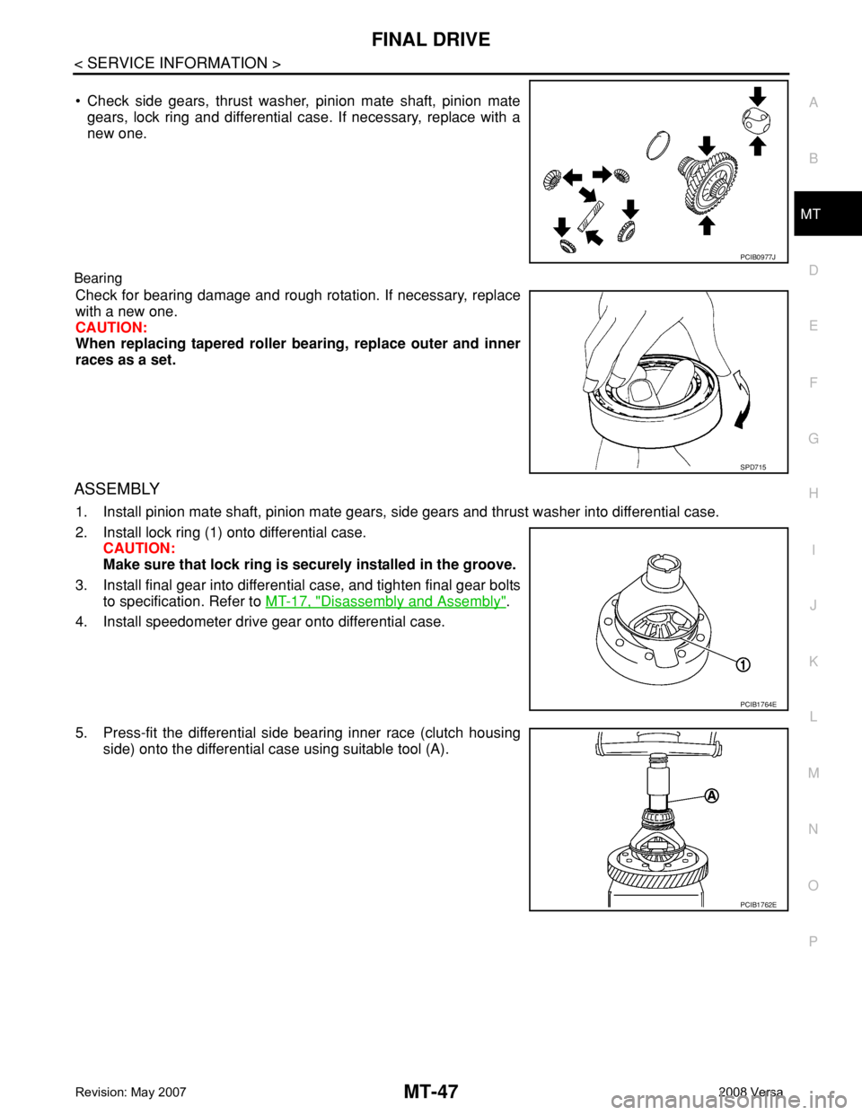
• Check side gears, thrust washer, pinion mate shaft, pinion mate
gears, lock ring and differential case. If necessary, replace with a
new one.
Bearing
Check for bearing damage and rough rotation. If necessary, replace
with a new one.
CAUTION:
When replacing tapered roller bearing, replace outer and inner
races as a set.
ASSEMBLY
1. Install pinion mate shaft, pinion mate gears, side gears and thrust washer into differential case.
2. Install lock ring (1) onto differential case.
CAUTION:
Make sure that lock ring is securely installed in the groove.
3. Install final gear into differential case, and tighten final gear bolts
to specification. Refer to MT-17, "
Disassembly and Assembly".
4. Install speedometer drive gear onto differential case.
5. Press-fit the differential side bearing inner race (clutch housing
side) onto the differential case using suitable tool (A).
PCIB0977J
SPD715
PCIB1764E
PCIB1762E
Page 2336 of 2771
MT-48
< SERVICE INFORMATION >
FINAL DRIVE
6. Press-fit the differential side bearing inner race (transaxle case
side) onto the differential case using suitable tool (A).
PCIB1763E