Page 1593 of 2771

ELECTRICAL LOAD SIGNAL
EC-519
< SERVICE INFORMATION >
C
D
E
F
G
H
I
J
K
L
MA
EC
N
P O
ELECTRICAL LOAD SIGNAL
CONSULT-II Reference Value in Data Monitor ModeINFOID:0000000001703057
Specification data are reference values.
Diagnosis ProcedureINFOID:0000000001703058
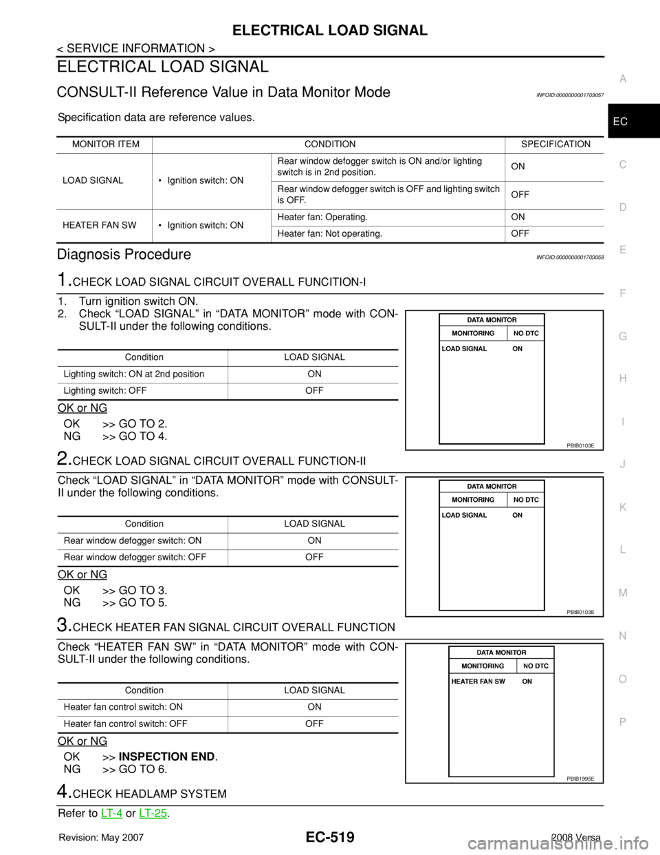
1.CHECK LOAD SIGNAL CIRCUIT OVERALL FUNCITION-I
1. Turn ignition switch ON.
2. Check “LOAD SIGNAL” in “DATA MONITOR” mode with CON-
SULT-II under the following conditions.
OK or NG
OK >> GO TO 2.
NG >> GO TO 4.
2.CHECK LOAD SIGNAL CIRCUIT OVERALL FUNCTION-II
Check “LOAD SIGNAL” in “DATA MONITOR” mode with CONSULT-
II under the following conditions.
OK or NG
OK >> GO TO 3.
NG >> GO TO 5.
3.CHECK HEATER FAN SIGNAL CIRCUIT OVERALL FUNCTION
Check “HEATER FAN SW” in “DATA MONITOR” mode with CON-
SULT-II under the following conditions.
OK or NG
OK >>INSPECTION END.
NG >> GO TO 6.
4.CHECK HEADLAMP SYSTEM
Refer to LT- 4
or LT- 2 5.
MONITOR ITEM CONDITION SPECIFICATION
LOAD SIGNAL • Ignition switch: ONRear window defogger switch is ON and/or lighting
switch is in 2nd position.ON
Rear window defogger switch is OFF and lighting switch
is OFF.OFF
HEATER FAN SW • Ignition switch: ONHeater fan: Operating. ON
Heater fan: Not operating. OFF
Condition LOAD SIGNAL
Lighting switch: ON at 2nd position ON
Lighting switch: OFF OFF
PBIB0103E
Condition LOAD SIGNAL
Rear window defogger switch: ON ON
Rear window defogger switch: OFF OFF
PBIB0103E
Condition LOAD SIGNAL
Heater fan control switch: ON ON
Heater fan control switch: OFF OFF
PBIB1995E
Page 1594 of 2771
EC-520
< SERVICE INFORMATION >
ELECTRICAL LOAD SIGNAL
>>INSPECTION END
5.CHECK REAR WINDOW DEFOGGER SYSTEM
Refer to GW-49
.
>>INSPECTION END
6.CHECK HEATER FAN CONTROL SYSTEM
Refer to MTC-22
.
>>INSPECTION END
Page 1622 of 2771

EC-548
< SERVICE INFORMATION >
SERVICE DATA AND SPECIFICATIONS (SDS)
SERVICE DATA AND SPECIFICATIONS (SDS)
Fuel PressureINFOID:0000000001703081
Idle Speed and Ignition TimingINFOID:0000000001703082
*: Under the following conditions:
• Air conditioner switch: OFF
• Electric load: OFF (Lights, heater fan & rear window defogger)
• Steering wheel: Kept in straight-ahead position
Calculated Load ValueINFOID:0000000001703083
Mass Air Flow SensorINFOID:0000000001703084
*: Engine is warmed up to normal operating temperature and running under no load.
Intake Air Temperature SensorINFOID:0000000001703085
Engine Coolant Temperature SensorINFOID:0000000001703086
Fuel pressure at idle
Approximately 350 kPa (3.57 kg/cm2, 51 psi)
Target idle speedA/T No load* (in P or N position)
700 ± 50 rpm CVT No load* (In P or N position)
M/T No load* (in Neutral position)
Air conditioner: ONA/T In P or N position
850 rpm or more CVT In P or N position
M/T In Neutral position
Ignition timingA/T In P or N position
13 ± 5° BTDC CVT In P or N position
M/T In Neutral position
Calculated load value% (Using CONSULT-II or GST)
At idle10 - 35
At 2,500 rpm10 - 35
Supply voltageBattery voltage (11 - 14V)
Output voltage at idle1.0 - 1.3*V
Mass air flow (Using CONSULT-II or GST)1.0 - 4.0 g·m/sec at idle*
2.0 - 10.0 g·m/sec at 2,500 rpm*
Temperature °C (°F) Resistance kΩ
25 (77)1.800 - 2.200
Temperature °C (°F) Resistance kΩ
20 (68)2.1 - 2.9
50 (122)0.68 - 1.00
90 (194)0.236 - 0.260
Page 1650 of 2771
DOOR OUTSIDE MOLDING
EI-27
< ON-VEHICLE REPAIR >
C
D
E
F
G
H
J
K
L
MA
B
EI
N
O
P
Sedan Models
Removal and InstallationINFOID:0000000001704229
FRONT DOOR OUTSIDE MOLDING
Removal
1. Open front door window.
2. Remove front door outside molding screw.
3. While pulling up on front of front door outside molding, insert a
suitable tool beneath the molding and release it from the door
top edge.
WIIA1411E
1. Front door outside molding 2. Rear door outside molding 3. Rear door corner cover
A. Clip C101
PIIB3386J
Page 1651 of 2771

EI-28
< ON-VEHICLE REPAIR >
DOOR OUTSIDE MOLDING
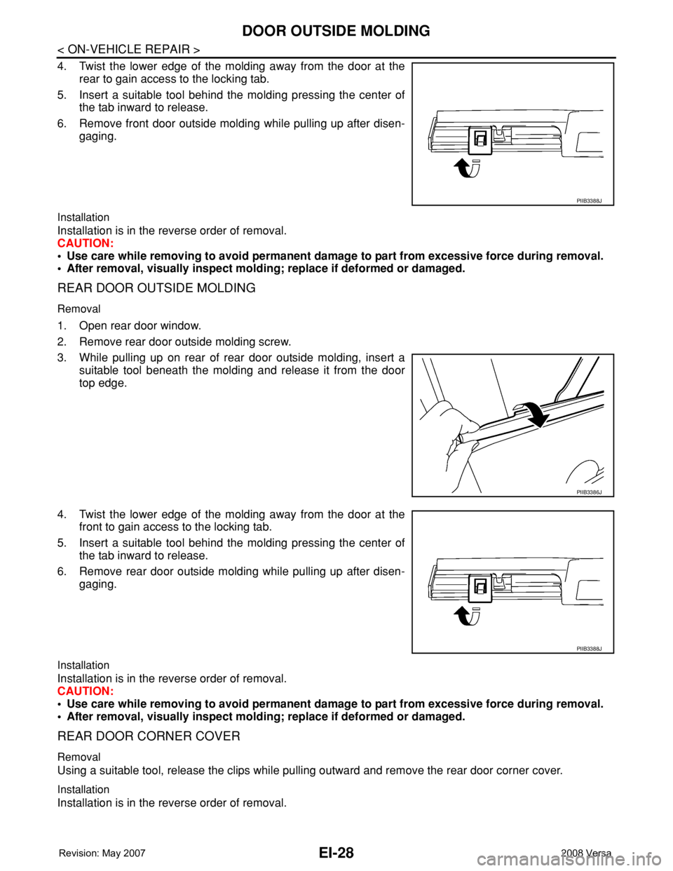
4. Twist the lower edge of the molding away from the door at the
rear to gain access to the locking tab.
5. Insert a suitable tool behind the molding pressing the center of
the tab inward to release.
6. Remove front door outside molding while pulling up after disen-
gaging.
Installation
Installation is in the reverse order of removal.
CAUTION:
• Use care while removing to avoid permanent damage to part from excessive force during removal.
• After removal, visually inspect molding; replace if deformed or damaged.
REAR DOOR OUTSIDE MOLDING
Removal
1. Open rear door window.
2. Remove rear door outside molding screw.
3. While pulling up on rear of rear door outside molding, insert a
suitable tool beneath the molding and release it from the door
top edge.
4. Twist the lower edge of the molding away from the door at the
front to gain access to the locking tab.
5. Insert a suitable tool behind the molding pressing the center of
the tab inward to release.
6. Remove rear door outside molding while pulling up after disen-
gaging.
Installation
Installation is in the reverse order of removal.
CAUTION:
• Use care while removing to avoid permanent damage to part from excessive force during removal.
• After removal, visually inspect molding; replace if deformed or damaged.
REAR DOOR CORNER COVER
Removal
Using a suitable tool, release the clips while pulling outward and remove the rear door corner cover.
Installation
Installation is in the reverse order of removal.
PIIB3388J
PIIB3386J
PIIB3388J
Page 1655 of 2771
EI-32
< ON-VEHICLE REPAIR >
DOOR FINISHER
DOOR FINISHER
Removal and InstallationINFOID:0000000001704233
FRONT DOOR
Removal
1. Open front door and front door window.
2. Disconnect the negative and positive battery cables.
3. Release the front door inside handle escutcheon pawls, then
slide the escutcheon rearward to remove from front door fin-
isher.
1. Power window and door lock/unlock
switch finisher2. Front door finisher 3. Inside handle escutcheon
Clip C101
LIIA2572E
PIIB6040E
Page 1656 of 2771
DOOR FINISHER
EI-33
< ON-VEHICLE REPAIR >
C
D
E
F
G
H
J
K
L
MA
B
EI
N
O
P
4. Insert a trim stick (A) or suitable tool into back edge of front door
power window and door lock/unlock switch finisher. Lift upward
to release the clips and remove.
5. Disconnect front door power window and door lock/unlock
switch harness connector.
6. Remove the (2) front door finisher screws.
7. Release the clips, then lift front door finisher upward to remove it
from door body panel.
Installation
Installation is in the reverse order of removal.
REAR DOOR
WIIA1237E
PIIB6042E
SIIA0810E
Page 1657 of 2771
EI-34
< ON-VEHICLE REPAIR >
DOOR FINISHER
Removal
1. Open rear door and rear door window.
2. Disconnect the negative and positive battery cables.
3. Release the rear door inside handle escutcheon pawls, then
slide the escutcheon rearward to remove from rear door finisher.
4. Insert a trim stick (A), or suitable tool into back edge of rear door
power window switch finisher. Lift upward to release the clips
and remove.
5. Disconnect rear door power window switch harness connector.
6. Remove rear door finisher screw.
1. Rear power window switch finisher 2. Rear door finisher 3. Inside handle escutcheon
Clip C101
LIIA2573E
PIIB6040E
WIIA1238E