2008 NISSAN LATIO window
[x] Cancel search: windowPage 471 of 2771
POWER DOOR LOCK SYSTEM
BL-37
< SERVICE INFORMATION >
C
D
E
F
G
H
J
K
L
MA
B
BL
N
O
P
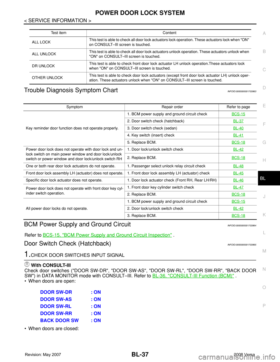
Trouble Diagnosis Symptom ChartINFOID:0000000001703963
BCM Power Supply and Ground CircuitINFOID:0000000001703964
Refer to BCS-15, "BCM Power Supply and Ground Circuit Inspection" .
Door Switch Check (Hatchback)INFOID:0000000001703965
1.CHECK DOOR SWITCHES INPUT SIGNAL
With CONSULT-III
Check door switches ("DOOR SW-DR", "DOOR SW-AS", "DOOR SW-RL", "DOOR SW-RR", "BACK DOOR
SW") in DATA MONITOR mode with CONSULT–III. Refer to BL-36, "
CONSULT-III Function (BCM)" .
• When doors are open:
• When doors are closed:
Test item Content
ALL LOCKThis test is able to check all door lock actuators lock operation. These actuators lock when "ON"
on CONSULT–III screen is touched.
ALL UNLOCKThis test is able to check all door lock actuators unlock operation. These actuators unlock when
"ON" on CONSULT–III screen is touched.
DR UNLOCKThis test is able to check front door lock actuator LH unlock operation.These actuators lock
when "ON" on CONSULT–III screen is touched.
OTHER UNLOCKThis test is able to check door lock actuators (except front door lock actuator LH) unlock oper-
ation. These actuators unlock when "ON" on CONSULT–III screen is touched.
Symptom Repair order Refer to page
Key reminder door function does not operate properly.1. BCM power supply and ground circuit checkBCS-15
2. Door switch check (hatchback)BL-37
3. Door switch check (sedan)BL-40
4. Key switch (insert) checkBL-41
5. Replace BCM.BCS-18
Power door lock does not operate with door lock and un-
lock switch on main power window and door lock/unlock
switch or power window and door lock/unlock switch RH1. Door lock/unlock switch checkBL-42
2. Replace BCM.BCS-18
One or both rear door lock actuators do not operate. 1. Passenger select unlock relay circuit checkBL-48
Front door lock assembly LH (actuator) does not operate. 1. Front door lock assembly LH (actuator) checkBL-45
Specific door lock actuator does not operate. 1. Door lock actuator check (Front RH, Rear LH/RH)BL-46
Power door lock does not operate with front door key cyl-
inder switch operation.1. Front door key cylinder switch checkBL-47
2. Replace BCM.BCS-18
All power door locks do not operate.1. BCM power supply and ground circuit checkBCS-152. Door lock/unlock switch checkBL-42
3. Replace BCM.BCS-18
DOOR SW-DR : ON
DOOR SW-AS : ON
DOOR SW-RL : ON
DOOR SW-RR : ON
BACK DOOR SW : ON
Page 477 of 2771
POWER DOOR LOCK SYSTEM
BL-43
< SERVICE INFORMATION >
C
D
E
F
G
H
J
K
L
MA
B
BL
N
O
P
OK or NG
OK >> Door lock and unlock switch is OK.
NG >> GO TO 2.
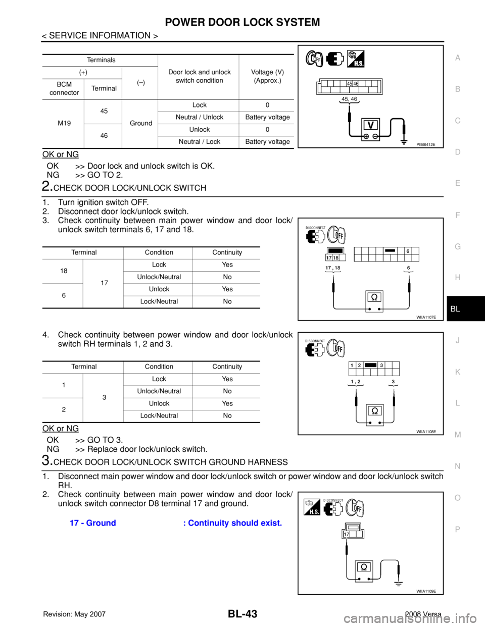
2.CHECK DOOR LOCK/UNLOCK SWITCH
1. Turn ignition switch OFF.
2. Disconnect door lock/unlock switch.
3. Check continuity between main power window and door lock/
unlock switch terminals 6, 17 and 18.
4. Check continuity between power window and door lock/unlock
switch RH terminals 1, 2 and 3.
OK or NG
OK >> GO TO 3.
NG >> Replace door lock/unlock switch.
3.CHECK DOOR LOCK/UNLOCK SWITCH GROUND HARNESS
1. Disconnect main power window and door lock/unlock switch or power window and door lock/unlock switch
RH.
2. Check continuity between main power window and door lock/
unlock switch connector D8 terminal 17 and ground.
Te r m i n a l s
Door lock and unlock
switch conditionVoltage (V)
(Approx.) (+)
(–)
BCM
connectorTe r m i n a l
M1945
GroundLock 0
Neutral / Unlock Battery voltage
46Unlock 0
Neutral / Lock Battery voltage
PIIB6412E
Terminal Condition Continuity
18
17Lock Yes
Unlock/Neutral No
6Unlock Yes
Lock/Neutral No
WIIA1107E
Terminal Condition Continuity
1
3Lock Yes
Unlock/Neutral No
2Unlock Yes
Lock/Neutral No
WIIA1108E
17 - Ground : Continuity should exist.
WIIA1109E
Page 478 of 2771
BL-44
< SERVICE INFORMATION >
POWER DOOR LOCK SYSTEM
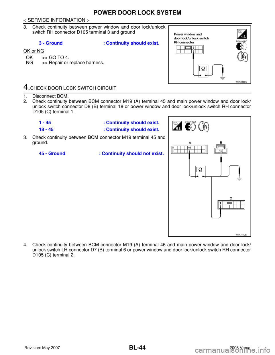
3. Check continuity between power window and door lock/unlock
switch RH connector D105 terminal 3 and ground
OK or NG
OK >> GO TO 4.
NG >> Repair or replace harness.
4.CHECK DOOR LOCK SWITCH CIRCUIT
1. Disconnect BCM.
2. Check continuity between BCM connector M19 (A) terminal 45 and main power window and door lock/
unlock switch connector D8 (B) terminal 18 or power window and door lock/unlock switch RH connector
D105 (C) terminal 1.
3. Check continuity between BCM connector M19 terminal 45 and
ground.
4. Check continuity between BCM connector M19 (A) terminal 46 and main power window and door lock/
unlock switch LH connector D7 (B) terminal 6 or power window and door lock/unlock switch RH connector
D105 (C) terminal 2.3 - Ground : Continuity should exist.
WIIA0450E
1 - 45 : Continuity should exist.
18 - 45 : Continuity should exist.
45 - Ground : Continuity should not exist.
W I I A 111 0 E
Page 480 of 2771
BL-46
< SERVICE INFORMATION >
POWER DOOR LOCK SYSTEM
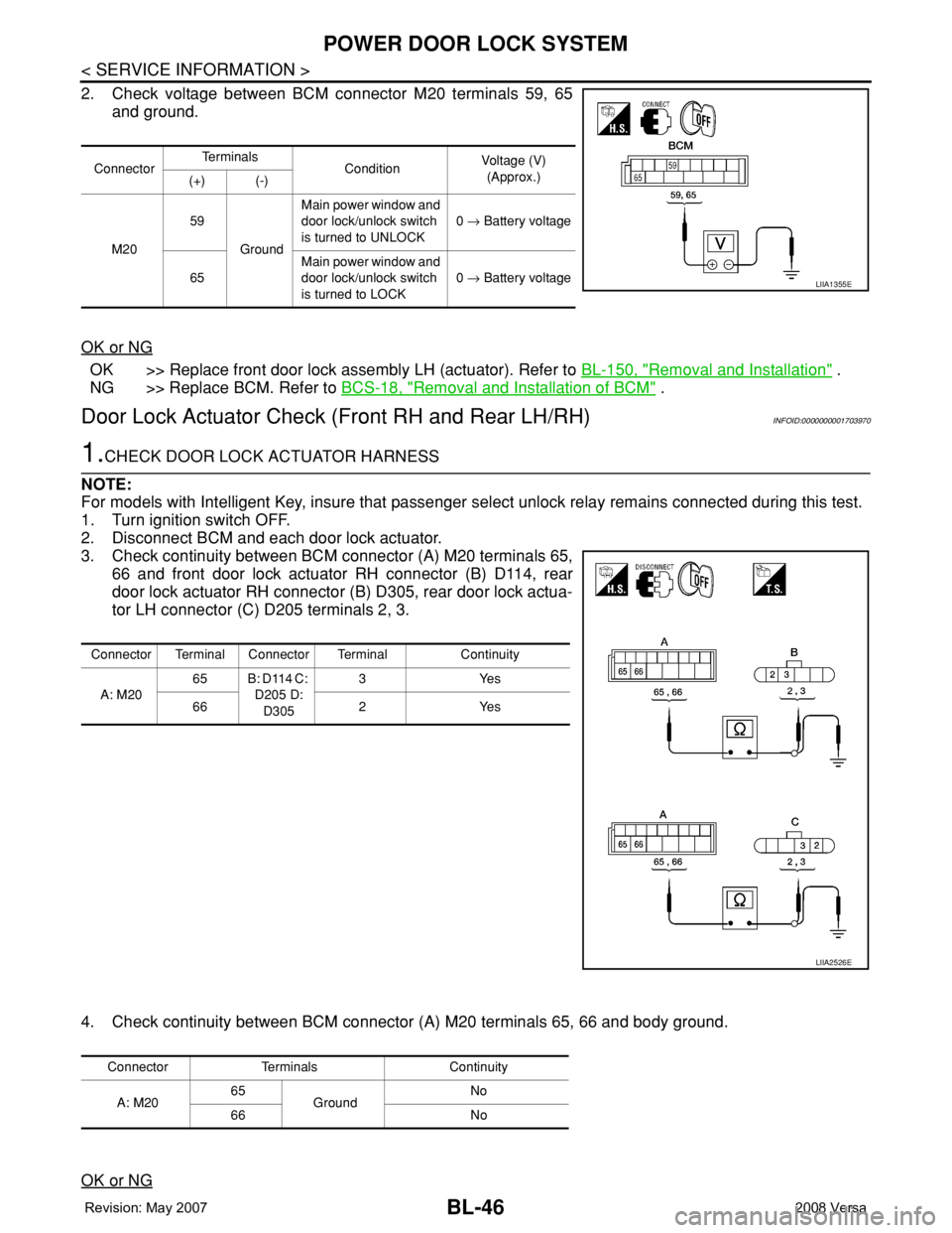
2. Check voltage between BCM connector M20 terminals 59, 65
and ground.
OK or NG
OK >> Replace front door lock assembly LH (actuator). Refer to BL-150, "Removal and Installation" .
NG >> Replace BCM. Refer to BCS-18, "
Removal and Installation of BCM" .
Door Lock Actuator Check (Front RH and Rear LH/RH)INFOID:0000000001703970
1.CHECK DOOR LOCK ACTUATOR HARNESS
NOTE:
For models with Intelligent Key, insure that passenger select unlock relay remains connected during this test.
1. Turn ignition switch OFF.
2. Disconnect BCM and each door lock actuator.
3. Check continuity between BCM connector (A) M20 terminals 65,
66 and front door lock actuator RH connector (B) D114, rear
door lock actuator RH connector (B) D305, rear door lock actua-
tor LH connector (C) D205 terminals 2, 3.
4. Check continuity between BCM connector (A) M20 terminals 65, 66 and body ground.
OK or NG
ConnectorTe r m i n a l s
ConditionVoltage (V)
(Approx.)
(+) (-)
M2059
GroundMain power window and
door lock/unlock switch
is turned to UNLOCK0 → Battery voltage
65Main power window and
door lock/unlock switch
is turned to LOCK0 → Battery voltage
LIIA1355E
Connector Terminal Connector Terminal Continuity
A: M2065 B: D114 C:
D205 D:
D3053Yes
66 2 Yes
LIIA2526E
Connector Terminals Continuity
A: M2065
GroundNo
66 No
Page 481 of 2771
POWER DOOR LOCK SYSTEM
BL-47
< SERVICE INFORMATION >
C
D
E
F
G
H
J
K
L
MA
B
BL
N
O
P
OK >> GO TO 2.
NG >> Check the following:
• Without Intelligent Key: Repair or replace harness.
• With Intelligent Key: For front doors, repair or replace harness.
• With Intelligent Key: For rear door, repair or replace harness or passenger select unlock relay.
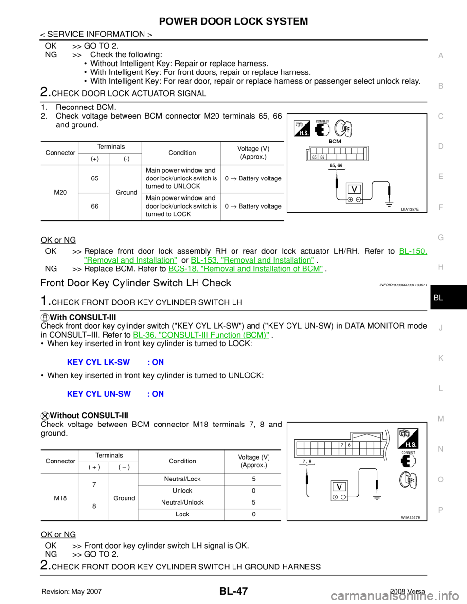
2.CHECK DOOR LOCK ACTUATOR SIGNAL
1. Reconnect BCM.
2. Check voltage between BCM connector M20 terminals 65, 66
and ground.
OK or NG
OK >> Replace front door lock assembly RH or rear door lock actuator LH/RH. Refer to BL-150,
"Removal and Installation" or BL-153, "Removal and Installation" .
NG >> Replace BCM. Refer to BCS-18, "
Removal and Installation of BCM" .
Front Door Key Cylinder Switch LH CheckINFOID:0000000001703971
1.CHECK FRONT DOOR KEY CYLINDER SWITCH LH
With CONSULT-III
Check front door key cylinder switch ("KEY CYL LK-SW") and ("KEY CYL UN-SW) in DATA MONITOR mode
in CONSULT–III. Refer to BL-36, "
CONSULT-III Function (BCM)" .
• When key inserted in front key cylinder is turned to LOCK:
• When key inserted in front key cylinder is turned to UNLOCK:
Without CONSULT-III
Check voltage between BCM connector M18 terminals 7, 8 and
ground.
OK or NG
OK >> Front door key cylinder switch LH signal is OK.
NG >> GO TO 2.
2.CHECK FRONT DOOR KEY CYLINDER SWITCH LH GROUND HARNESS
ConnectorTe r m i n a l s
ConditionVoltage (V)
(Approx.)
(+) (-)
M2065
GroundMain power window and
door lock/unlock switch is
turned to UNLOCK0 → Battery voltage
66Main power window and
door lock/unlock switch is
turned to LOCK0 → Battery voltage
LIIA1357E
KEY CYL LK-SW : ON
KEY CYL UN-SW : ON
ConnectorTe r m i n a l s
ConditionVoltage (V)
(Approx.)
( + ) ( – )
M187
GroundNeutral/Lock 5
Unlock 0
8Neutral/Unlock 5
Lock 0
WIIA1247E
Page 484 of 2771
BL-50
< SERVICE INFORMATION >
POWER DOOR LOCK SYSTEM
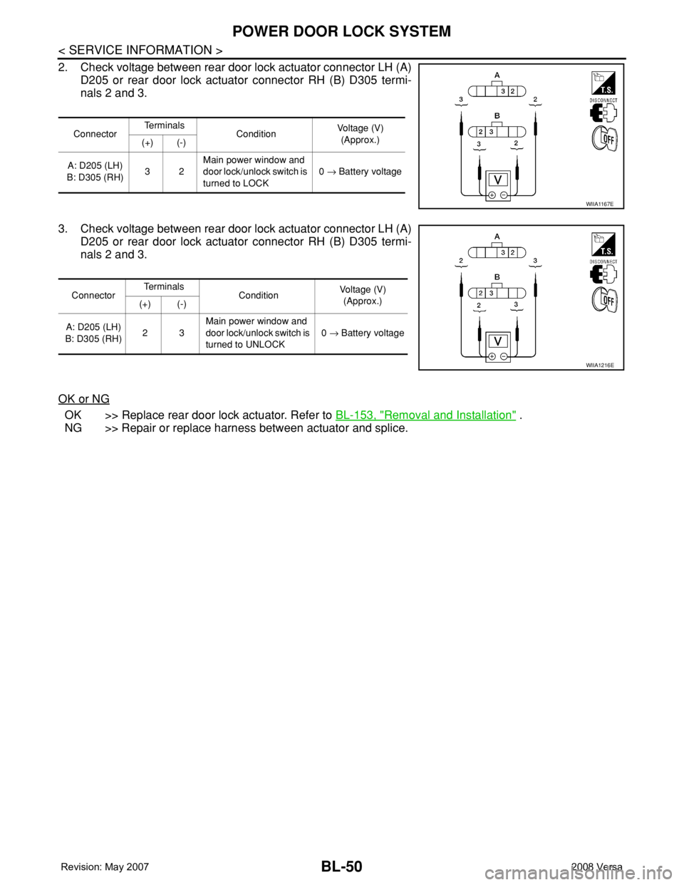
2. Check voltage between rear door lock actuator connector LH (A)
D205 or rear door lock actuator connector RH (B) D305 termi-
nals 2 and 3.
3. Check voltage between rear door lock actuator connector LH (A)
D205 or rear door lock actuator connector RH (B) D305 termi-
nals 2 and 3.
OK or NG
OK >> Replace rear door lock actuator. Refer to BL-153, "Removal and Installation" .
NG >> Repair or replace harness between actuator and splice.
ConnectorTe r m i n a l s
ConditionVoltage (V)
(Approx.)
(+) (-)
A: D205 (LH)
B: D305 (RH)32Main power window and
door lock/unlock switch is
turned to LOCK0 → Battery voltage
WIIA1167E
ConnectorTe r m i n a l s
ConditionVoltage (V)
(Approx.)
(+) (-)
A: D205 (LH)
B: D305 (RH)23Main power window and
door lock/unlock switch is
turned to UNLOCK0 → Battery voltage
WIIA1216E
Page 516 of 2771

BL-82
< SERVICE INFORMATION >
INTELLIGENT KEY SYSTEM
List of Operation Related Parts
Parts marked with × are the parts related to operation.
P position warning (CVT)When selector lever is in other than P po-
sition, ignition switch is turned from ON to
OFF.activate — — — Flash
OFF position warn-
ing chimeFor internal• Ignition switch is turned from ACC to
OFF.
[ignition switch is pressed (ignition knob
switch is ON).]
• Ignition switch is in the LOCK position
and pressed for 1 second.activate — — Flash —
For externalWhen driver door is opened and then
closed while the OFF position warning
chime above is operating—activate—— —
Ta k e a w a y w a r n i n gRight after
door is closedRight after door is closed and the following
conditions are met.
• Ignition knob is pressed and in rotatable
or rotated state
• Intelligent Key can not be detected in-
side the vehicle—activateFlash
(red)——
Any door is
openedAny door is opened and the following con-
ditions are met.
• Ignition knob is pressed and in rotatable
or rotated state
• Intelligent Key unit will perform key ID
verification with Intelligent Key through
inside key antenna every 5 second, if
the key ID verification is NG.——Flash
(red)——
Ta k e a w a y
from the win-
dowTake away from the window and the fol-
lowing conditions are met.
• Ignition knob is pressed and in rotatable
or rotated state
• Vehicle speed below 5 km/h (3 m.p.h.)
• Intelligent Key unit will perform key ID
verification with Intelligent Key through
inside key antenna every 30 second, if
the key ID verification is NG.
(This warning function will be disabled if
mechanical key is inserted into the key
cylinder.)
NOTE:
Default setting of this function is OFF.activate —Flash
(red)——
Door lock opera-
tion warningLock opera-
tion with re-
quest switchLock operation with request switch and
the following condition is met.
• Intelligent Key is inside the vehicle—activate—— —
Intelligent Key low battery warningWhen Intelligent Key is low battery, Intelli-
gent Key unit is detected after ignition
switch is turned ON.——Flash
(green)—— Operation ConditionWarning chime/buzzer Warning lamp
Chime
(combina-
tion meter)Buzzer(s) KEYLOCK
(M/T)P-SHIFT
(CVT)
Page 517 of 2771
INTELLIGENT KEY SYSTEM
BL-83
< SERVICE INFORMATION >
C
D
E
F
G
H
J
K
L
MA
B
BL
N
O
P
CHANGE SETTINGS FUNCTION
The settings for each function can be changed with the CONSULT-III.
Changing Settings Using CONSULT-III
The settings for the Intelligent Key system functions can be changed using CONSULT-III (WORK SUPPORT).
Refer to BL-101, "
CONSULT-III Application Item".
NOTE:
Once a function setting is changed, it will remain effective even if the battery is disconnected.
INTELLIGENT KEY REGISTRATION
Intelligent Key-ID registration is performed using the CONSULT-III.
CAUTION:
• After a new Intelligent Key-ID is registered, be sure to check the function.
• When registering an additional Intelligent Key-ID, take any Intelligent Keys already registered and
Intelligent Keys for any other vehicles out of the vehicle before starting.
CONSULT-III can be used to check and delete Intelligent Key-IDs.
For further information, see the CONSULT-III Operation Manual NATS.
STEERING LOCK SOLENOID REGISTRATION
Steering Lock Solenoid ID Registration
CAUTION:
• The method for registering a steering lock solenoid ID depends on the status of the steering lock
solenoid and Intelligent Key unit (new or old unit).
• After registration is completed, press ignition switch with an Intelligent Key in the vehicle so that it
can be turned, and confirm that it cannot be turned even when ignition switch is pressed without an
Intelligent Key in the vehicle.
For further information, see the CONSULT-III Operation Manual NATS-IVIS/NVIS.
CAN Communication System DescriptionINFOID:0000000001704000
Refer to LAN-6.
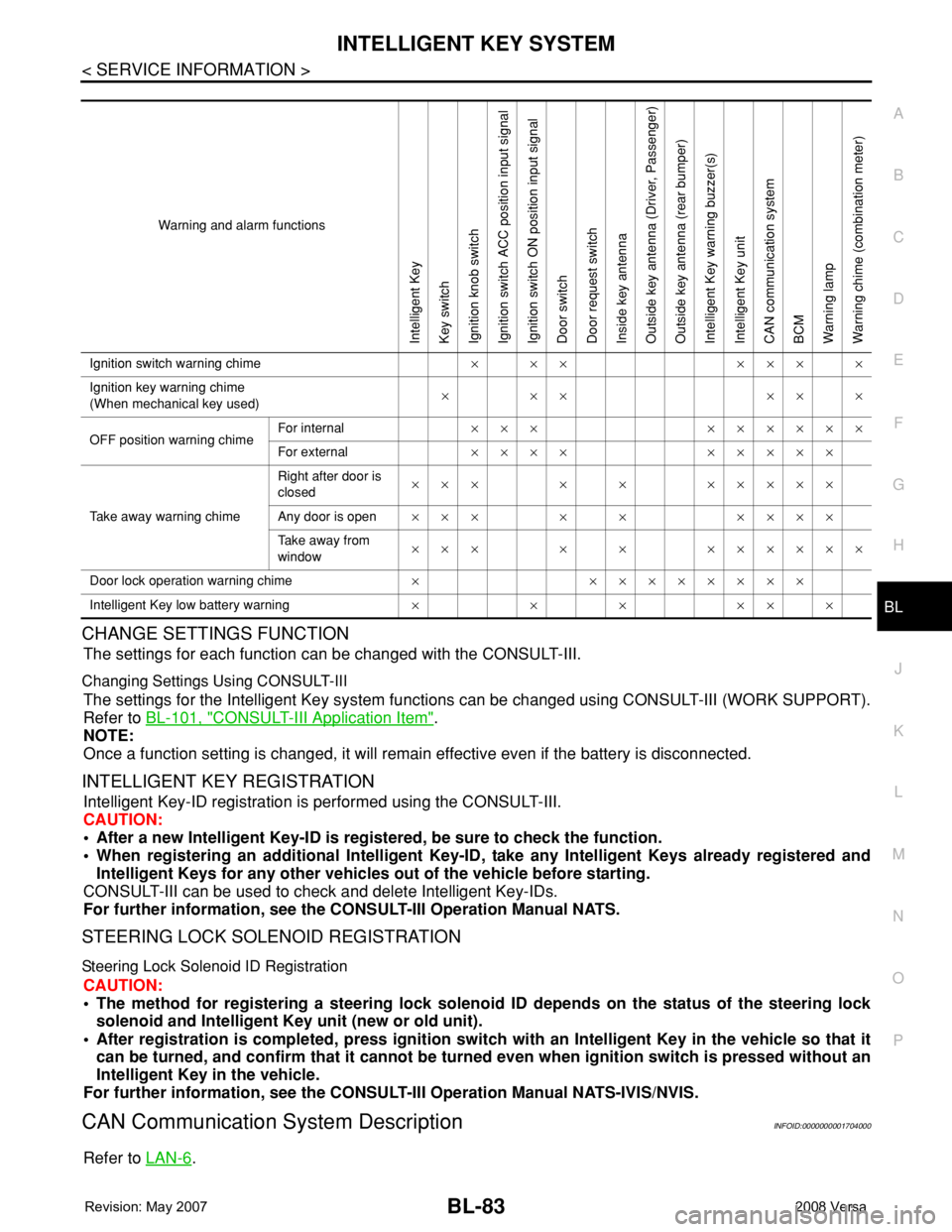
Warning and alarm functions
Intelligent Key
Key switch
Ignition knob switch
Ignition switch ACC position input signal
Ignition switch ON position input signal
Door switch
Door request switch
Inside key antenna
Outside key antenna (Driver, Passenger)
Outside key antenna (rear bumper)
Intelligent Key warning buzzer(s)
Intelligent Key unit
CAN communication system
BCM
Warning lamp
Warning chime (combination meter)
Ignition switch warning chime× ×× ××× ×
Ignition key warning chime
(When mechanical key used)××× ×××
OFF position warning chimeFor internal××× ××××××
For external×××× ×××××
Take away warning chimeRight after door is
closed××× × × ×××××
Any door is open××× × × ××××
Take away from
window××× × × ××××××
Door lock operation warning chime× ××××××××
Intelligent Key low battery warning××××××