2008 INFINITI FX35 turn signal
[x] Cancel search: turn signalPage 3686 of 3924
AUTOMATIC DRIVE POSITIONERSE-47
< SERVICE INFORMATION >
C
DE
F
G H
J
K L
M A
B
SE
N
O P
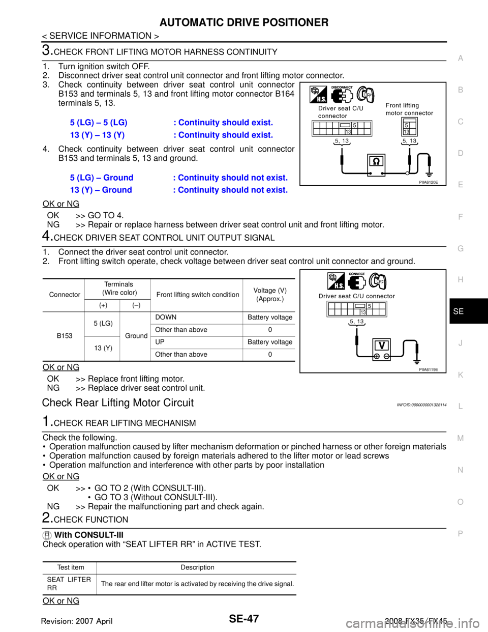
3.CHECK FRONT LIFTING MO TOR HARNESS CONTINUITY
1. Turn ignition switch OFF.
2. Disconnect driver seat control unit connector and front lifting motor connector.
3. Check continuity between driver seat control unit connector B153 and terminals 5, 13 and front lifting motor connector B164
terminals 5, 13.
4. Check continuity between driver seat control unit connector B153 and terminals 5, 13 and ground.
OK or NG
OK >> GO TO 4.
NG >> Repair or replace harness between driver seat control unit and front lifting motor.
4.CHECK DRIVER SEAT CONTROL UNIT OUTPUT SIGNAL
1. Connect the driver seat control unit connector.
2. Front lifting switch operate, check voltage bet ween driver seat control unit connector and ground.
OK or NG
OK >> Replace front lifting motor.
NG >> Replace driver seat control unit.
Check Rear Lifting Motor CircuitINFOID:0000000001328114
1.CHECK REAR LIFTING MECHANISM
Check the following.
Operation malfunction caused by lifter mechanism deformation or pinched harness or other foreign materials
Operation malfunction caused by foreign materials adhered to the lifter motor or lead screws
Operation malfunction and interference with other parts by poor installation
OK or NG
OK >> GO TO 2 (With CONSULT-III). GO TO 3 (Without CONSULT-III).
NG >> Repair the malfunctioning part and check again.
2.CHECK FUNCTION
With CONSULT-III
Check operation with “SEAT LIFTER RR” in ACTIVE TEST.
OK or NG
5 (LG) – 5 (LG) : Cont inuity should exist.
13 (Y) – 13 (Y) : Continuity should exist.
5 (LG) – Ground : Contin uity should not exist.
13 (Y) – Ground : Continuity should not exist.
PIIA6120E
Connector Te r m i n a l s
(Wire color) Front lifting switch condition Voltage (V)
(Approx.)
(+) (–)
B153 5 (LG)
GroundDOWN Battery voltage
Other than above 0
13 (Y) UP Battery voltage
Other than above 0
PIIA6119E
Test item Description
SEAT LIFTER
RR The rear end lifter motor is activated by receiving the drive signal.
3AA93ABC3ACD3AC03ACA3AC03AC63AC53A913A773A893A873A873A8E3A773A983AC73AC93AC03AC3
3A893A873A873A8F3A773A9D3AAF3A8A3A8C3A863A9D3AAF3A8B3A8C
Page 3687 of 3924
SE-48
< SERVICE INFORMATION >
AUTOMATIC DRIVE POSITIONER
OK >> Rear lifting motor check is OK.
NG >> GO TO 3.
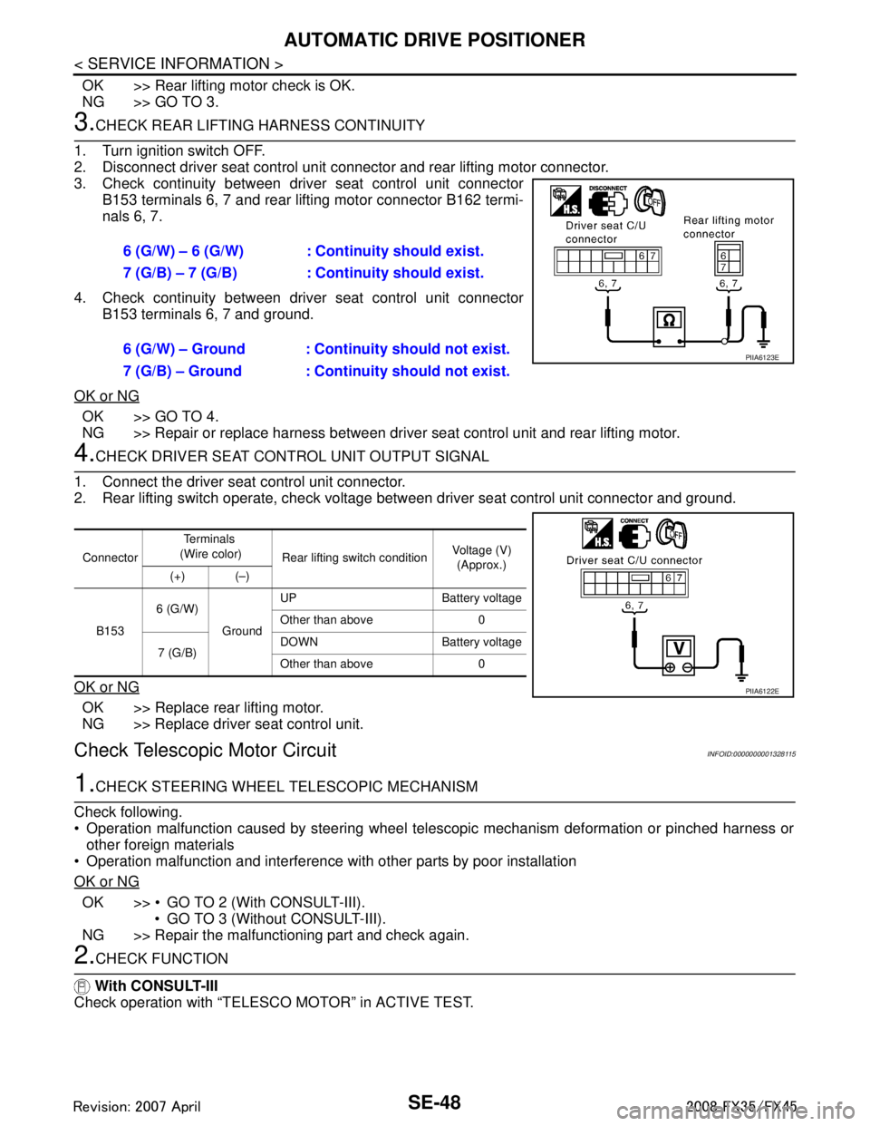
3.CHECK REAR LIFTING HARNESS CONTINUITY
1. Turn ignition switch OFF.
2. Disconnect driver seat control unit connector and rear lifting motor connector.
3. Check continuity between driv er seat control unit connector
B153 terminals 6, 7 and rear lifting motor connector B162 termi-
nals 6, 7.
4. Check continuity between driv er seat control unit connector
B153 terminals 6, 7 and ground.
OK or NG
OK >> GO TO 4.
NG >> Repair or replace harness between driver seat control unit and rear lifting motor.
4.CHECK DRIVER SEAT CONTROL UNIT OUTPUT SIGNAL
1. Connect the driver seat control unit connector.
2. Rear lifting switch operate, check voltage between driver seat control unit connector and ground.
OK or NG
OK >> Replace rear lifting motor.
NG >> Replace driver seat control unit.
Check Telescopic Motor CircuitINFOID:0000000001328115
1.CHECK STEERING WHEEL TELESCOPIC MECHANISM
Check following.
Operation malfunction caused by steering wheel telescopic mechanism deformation or pinched harness or other foreign materials
Operation malfunction and interference wit h other parts by poor installation
OK or NG
OK >> GO TO 2 (With CONSULT-III). GO TO 3 (Without CONSULT-III).
NG >> Repair the malfunctioning part and check again.
2.CHECK FUNCTION
With CONSULT-III
Check operation with “TELESCO MOTOR” in ACTIVE TEST. 6 (G/W) – 6 (G/W) : Co
ntinuity should exist.
7 (G/B) – 7 (G/B) : Co ntinuity should exist.
6 (G/W) – Ground : Continuity should not exist.
7 (G/B) – Ground : Continuity should not exist.
PIIA6123E
Connector Te r m i n a l s
(Wire color) Rear lifting switch condition Voltage (V)
(Approx.)
(+) (–)
B153 6 (G/W)
GroundUP Battery voltage
Other than above 0
7 (G/B) DOWN Battery voltage
Other than above 0
PIIA6122E
3AA93ABC3ACD3AC03ACA3AC03AC63AC53A913A773A893A873A873A8E3A773A983AC73AC93AC03AC3
3A893A873A873A8F3A773A9D3AAF3A8A3A8C3A863A9D3AAF3A8B3A8C
Page 3688 of 3924
AUTOMATIC DRIVE POSITIONERSE-49
< SERVICE INFORMATION >
C
DE
F
G H
J
K L
M A
B
SE
N
O P
OK or NG
OK >> Steering telescopic motor circuit is OK.
NG >> GO TO 3.
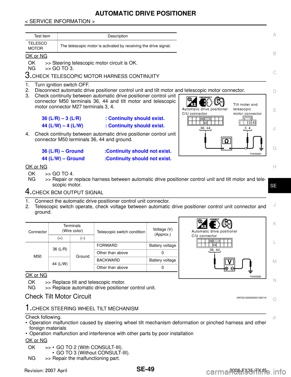
3.CHECK TELESCOPIC MOTO R HARNESS CONTINUITY
1. Turn ignition switch OFF.
2. Disconnect automatic drive positioner control unit and tilt motor and telescopic motor connector.
3. Check continuity between automat ic drive positioner control unit
connector M50 terminals 36, 44 and tilt motor and telescopic
motor connector M27 terminals 3, 4.
4. Check continuity between automat ic drive positioner control unit
connector M50 terminals 36, 44 and ground.
OK or NG
OK >> GO TO 4.
NG >> Repair or replace harness between automatic dr ive positioner control unit and tilt motor and tele-
scopic motor.
4.CHECK BCM OUTPUT SIGNAL
1. Connect the automatic drive positioner control unit connector.
2. Telescopic switch operate, check voltage between aut omatic drive positioner control unit connector and
ground.
OK or NG
OK >> Replace tilt and telescopic motor.
NG >> Replace automatic drive positioner control unit.
Check Tilt Motor CircuitINFOID:0000000001328116
1.CHECK STEERING WH EEL TILT MECHANISM
Check following.
Operation malfunction caused by steering wheel t ilt mechanism deformation or pinched harness and other
foreign materials
Operation malfunction and interference with other parts by poor installation
OK or NG
OK >> GO TO 2 (With CONSULT-III). GO TO 3 (Without CONSULT-III).
NG >> Repair the malfunctioning part.
Test item Description
TELESCO
MOTOR The telescopic motor is activated by receiving the drive signal.
36 (L/R) – 3 (L/R) : Co
ntinuity should exist.
44 (L/W) – 4 (L/W) : Co ntinuity should exist.
36 (L/R) – Ground :Continuity should not exist.
44 (L/W) – Ground :Continuity should not exist.
PIIA5066E
Connector Te r m i n a l s
(Wire color) Telescopic switch condition Voltage (V)
(Approx.)
(+) (–)
M50 36 (L/R)
GroundFORWARD Battery voltage
Other than above 0
44 (L/W) BACKWARD Battery voltage
Other than above 0
PIIA5068E
3AA93ABC3ACD3AC03ACA3AC03AC63AC53A913A773A893A873A873A8E3A773A983AC73AC93AC03AC3
3A893A873A873A8F3A773A9D3AAF3A8A3A8C3A863A9D3AAF3A8B3A8C
Page 3689 of 3924
SE-50
< SERVICE INFORMATION >
AUTOMATIC DRIVE POSITIONER
2.CHECK FUNCTION
With CONSULT-III
Check operation with “TILT MOTOR” in ACTIVE TEST.
OK or NG
OK >> Steering tilt motor circuit is OK.
NG >> GO TO 3.
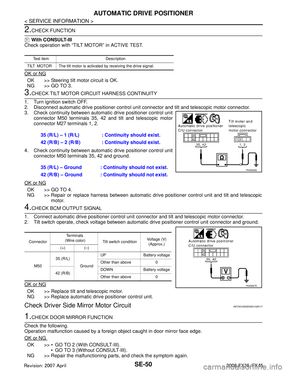
3.CHECK TILT MOTOR CIRCUIT HARNESS CONTINUITY
1. Turn ignition switch OFF.
2. Disconnect automatic drive positioner control uni t connector and tilt and telescopic motor connector.
3. Check continuity between automat ic drive positioner control unit
connector M50 terminals 35, 42 and tilt and telescopic motor
connector M27 terminals 1, 2.
4. Check continuity between automat ic drive positioner control unit
connector M50 terminals 35, 42 and ground.
OK or NG
OK >> GO TO 4.
NG >> Repair or replace harness between automatic dr ive positioner control unit and tilt and telescopic
motor.
4.CHECK BCM OUTPUT SIGNAL
1. Connect automatic drive positioner control unit connector and tilt and telescopic motor connector.
2. Tilt switch operate, check voltage between automat ic drive positioner control unit connector and ground.
OK or NG
OK >> Replace tilt and telescopic motor.
NG >> Replace automatic drive positioner control unit.
Check Driver Side Mirror Motor CircuitINFOID:0000000001328117
1.CHECK DOOR MIRROR FUNCTION
Check the following.
Operation malfunction caused by a foreign object caught in door mirror face edge.
OK or NG
OK >> GO TO 2 (With CONSULT-III). GO TO 3 (Without CONSULT-III).
NG >> Repair the malfunctioning parts, and check the symptom again.
Te s t i t e m D e s c r i p t i o n
TILT MOTOR The tilt motor is activated by receiving the drive signal.
35 (R/L) – 1 (R/L) : Co ntinuity should exist.
42 (R/B) – 2 (R/B) : Continuity should exist.
35 (R/L) – Ground : Continuity should not exist.
42 (R/B) – Ground : Continuity should not exist.
PIIA5065E
Connector Te r m i n a l s
(Wire color) Tilt switch condition Voltage (V)
(Approx.)
(+) (–)
M50 35 (R/L)
GroundUP Battery voltage
Other than above 0
42 (R/B) DOWN Battery voltage
Other than above 0
PIIA5067E
3AA93ABC3ACD3AC03ACA3AC03AC63AC53A913A773A893A873A873A8E3A773A983AC73AC93AC03AC3
3A893A873A873A8F3A773A9D3AAF3A8A3A8C3A863A9D3AAF3A8B3A8C
Page 3690 of 3924

AUTOMATIC DRIVE POSITIONERSE-51
< SERVICE INFORMATION >
C
DE
F
G H
J
K L
M A
B
SE
N
O P
2.CHECK MIRROR MOTOR
With CONSULT-III
Check the operation with “MIRROR MO TOR LH” in the ACTIVE TEST.
OK or NG
OK >> Driver side mirror motor circuit is OK.
NG >> GO TO 3.
3.CHECK DOOR MIRROR MOTOR (DRI VER SIDE) HARNESS CONTINUITY
1. Turn ignition switch OFF.
2. Disconnect automatic drive positioner control uni t connector and door mirror (driver side) connector.
3. Check continuity between automat ic drive positioner control unit
connector M49 terminal 16, 31, 32 and door mirror (driver side)
connector D2 terminal 11, 12, 13.
4. Check continuity between automat ic drive positioner control unit
connector M49 terminal 16, 31, 32 and ground.
OK or NG
OK >> GO TO 4.
NG >> Repair or replace harness between automatic dr ive positioner control unit and door mirror (driver
side).
4.CHECK MIRROR MOTOR SIGNAL
1. Connect automatic drive positioner contro l unit and door mirror (driver side) connector.
2. Turn ignition switch ACC.
3. Turn changeover switch LH position.
4. Mirror switch operate, check voltage betw een door mirror (driver side) connector and ground.
OK or NG
OK >> Replace door mirror motor (driver side).
NG >> Check the condition of the harness and the connector.
Test item Description
MIRROR MOTOR LH The LH mirror motor move
s the mirror UP/DOWN and
LEFT/RIGHT by receiving the drive signal.
16 (P) – 13 (P) : Continuity should exist.
31 (R/W) – 11 (GY) : Continuity should exist.
32 (G/B) – 12 (PU) : Continuity should exist.
16 (P) – Ground : Continuity should not exist.
31 (R/W) – Ground : Continuity should not exist.
32 (G/B) – Ground : Continuity should not exist.
PIIB8581E
Connector Te r m i n a l s
(Wire color) Mirror switch condition Voltage (V)
(Approx.)
(+) (–)
D2 11 ( G Y )
Ground UP Battery voltage
Other than above 0
12 (PU) LEFT Battery voltage
Other than above 0
13 (P) DOWN or RIGHT Battery voltage
Other than above 0
PIIB8582E
3AA93ABC3ACD3AC03ACA3AC03AC63AC53A913A773A893A873A873A8E3A773A983AC73AC93AC03AC3
3A893A873A873A8F3A773A9D3AAF3A8A3A8C3A863A9D3AAF3A8B3A8C
Page 3691 of 3924
SE-52
< SERVICE INFORMATION >
AUTOMATIC DRIVE POSITIONER
Check Passenger Side Mirror Motor Circuit
INFOID:0000000001328118
1.CHECK DOOR MIRROR FUNCTION
Check the following.
Operation malfunction caused by a foreign object caught in door mirror face edge.
OK or NG
OK >> GO TO 2 (With CONSULT-III). GO TO 3 (WIthout CONSULT-III).
NG >> Repair the malfunctioning parts, and check the symptom again.
2.CHECK MIRROR MOTOR
With CONSULT-III
Check the operation with “MIRROR MOTOR RH” in the ACTIVE TEST.
OK or NG
OK >> Passenger side mirror motor circuit is OK.
NG >> GO TO 3.
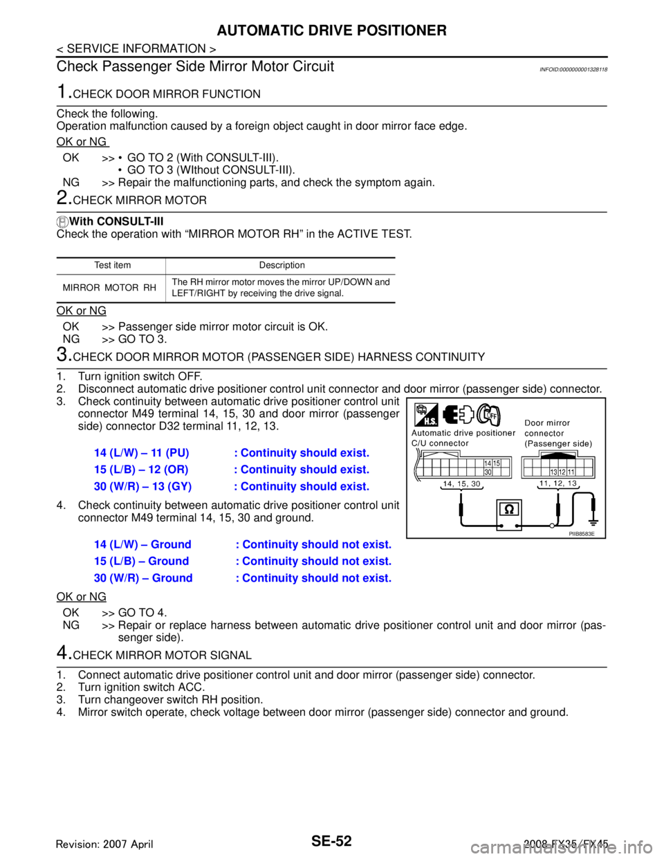
3.CHECK DOOR MIRROR MOTOR (PASSE NGER SIDE) HARNESS CONTINUITY
1. Turn ignition switch OFF.
2. Disconnect automatic drive positioner control uni t connector and door mirror (passenger side) connector.
3. Check continuity between automat ic drive positioner control unit
connector M49 terminal 14, 15, 30 and door mirror (passenger
side) connector D32 terminal 11, 12, 13.
4. Check continuity between automat ic drive positioner control unit
connector M49 terminal 14, 15, 30 and ground.
OK or NG
OK >> GO TO 4.
NG >> Repair or replace harness between automatic drive positioner control unit and door mirror (pas-
senger side).
4.CHECK MIRROR MOTOR SIGNAL
1. Connect automatic drive positioner control unit and door mirror (passenger side) connector.
2. Turn ignition switch ACC.
3. Turn changeover switch RH position.
4. Mirror switch operate, check voltage between door mirror (passenger side) connector and ground.
Te s t i t e m D e s c r i p t i o n
MIRROR MOTOR RH The RH mirror motor moves
the mirror UP/DOWN and
LEFT/RIGHT by receiving the drive signal.
14 (L/W) – 11 (PU) : Co ntinuity should exist.
15 (L/B) – 12 (OR) : Cont inuity should exist.
30 (W/R) – 13 (GY) : Cont inuity should exist.
14 (L/W) – Ground : Continuity should not exist.
15 (L/B) – Ground : Continuity should not exist.
30 (W/R) – Ground : Continuity should not exist.
PIIB8583E
3AA93ABC3ACD3AC03ACA3AC03AC63AC53A913A773A893A873A873A8E3A773A983AC73AC93AC03AC3
3A893A873A873A8F3A773A9D3AAF3A8A3A8C3A863A9D3AAF3A8B3A8C
Page 3692 of 3924
AUTOMATIC DRIVE POSITIONERSE-53
< SERVICE INFORMATION >
C
DE
F
G H
J
K L
M A
B
SE
N
O P
OK or NG
OK >> Replace door mirror motor (passenger side).
NG >> Check the condition of the harness and connector.
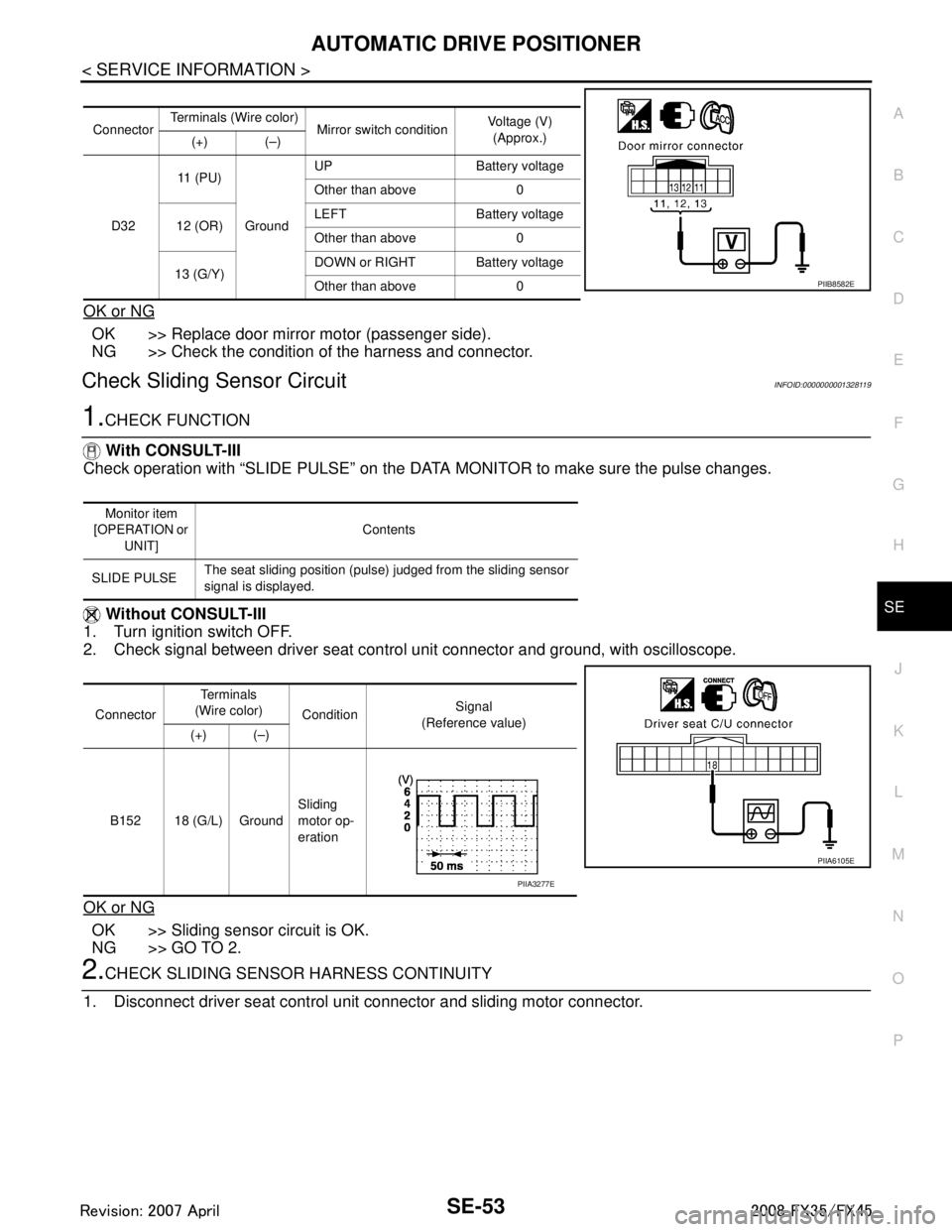
Check Sliding Sensor CircuitINFOID:0000000001328119
1.CHECK FUNCTION
With CONSULT-III
Check operation with “SLIDE PULSE” on the DATA MONITOR to make sure the pulse changes.
Without CONSULT-III
1. Turn ignition switch OFF.
2. Check signal between driver seat control unit connector and ground, with oscilloscope.
OK or NG
OK >> Sliding sensor circuit is OK.
NG >> GO TO 2.
2.CHECK SLIDING SENSOR HARNESS CONTINUITY
1. Disconnect driver seat control unit connector and sliding motor connector.
Connector Terminals (Wire color)
Mirror switch condition Voltage (V)
(Approx.)
(+) (–)
D32 11 ( P U )
Ground UP Battery voltage
Other than above 0
12 (OR) LEFT Battery voltage
Other than above 0
13 (G/Y) DOWN or RIGHT Battery voltage
Other than above 0
PIIB8582E
Monitor item
[OPERATION or
UNIT] Contents
SLIDE PULSE The seat sliding position (pulse) judged from the sliding sensor
signal is displayed.
Connector Te r m i n a l s
(Wire color) Condition Signal
(Reference value)
(+) (–)
B152 18 (G/L) Ground Sliding
motor op-
eration
PIIA6105E
PIIA3277E
3AA93ABC3ACD3AC03ACA3AC03AC63AC53A913A773A893A873A873A8E3A773A983AC73AC93AC03AC3
3A893A873A873A8F3A773A9D3AAF3A8A3A8C3A863A9D3AAF3A8B3A8C
Page 3693 of 3924
SE-54
< SERVICE INFORMATION >
AUTOMATIC DRIVE POSITIONER
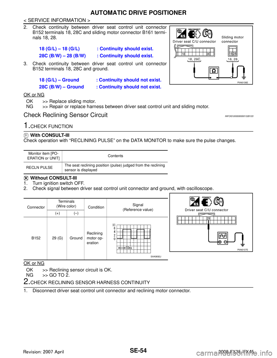
2. Check continuity between driver seat control unit connector
B152 terminals 18, 28C and sliding motor connector B161 termi-
nals 18, 28.
3. Check continuity between driv er seat control unit connector
B152 terminals 18, 28C and ground.
OK or NG
OK >> Replace sliding motor.
NG >> Repair or replace harness between driver seat control unit and sliding motor.
Check Reclining Sensor CircuitINFOID:0000000001328120
1.CHECK FUNCTION
With CONSULT-III
Check operation with “RECLINING PULSE” on the DATA MONITOR to make sure the pulse changes.
Without CONSULT-III
1. Turn ignition switch OFF.
2. Check signal between driver seat contro l unit connector and ground, with oscilloscope.
OK or NG
OK >> Reclining sensor circuit is OK.
NG >> GO TO 2.
2.CHECK RECLINING SENSOR HARNESS CONTINUITY
1. Disconnect driver seat control unit connector and reclining motor connector. 18 (G/L) – 18 (G/L) : Cont
inuity should exist.
28C (B/W) – 28 (B/W) : Continuity should exist.
18 (G/L) – Ground : Continuity should not exist.
28C (B/W) – Ground : Continuity should not exist.
PIIA6106E
Monitor item [PO-
ERATION or UNIT] Contents
RECLN PULSE The seat reclining position (pulse) judged from the reclining
sensor is displayed
Connector Te r m i n a l s
(Wire color) Condition Signal
(Reference value)
(+) (–)
B152 29 (G) Ground Reclining
motor op-
eration
PIIA6107E
SIIA0692J
3AA93ABC3ACD3AC03ACA3AC03AC63AC53A913A773A893A873A873A8E3A773A983AC73AC93AC03AC3
3A893A873A873A8F3A773A9D3AAF3A8A3A8C3A863A9D3AAF3A8B3A8C